Zeta SCM-ACM Smart Connect Multi Loop Alarm Circuit Module
General
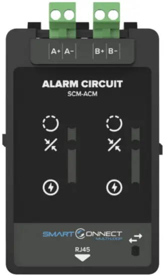
The SCM-ACM is a plug-in sounder module for the Smart Connect Multi-loop panel. It has two sounder circuits rated at 500mA. Each circuit is supervised for open, short and earth fault conditions.
An additional feature of the SCM-ACM module is that it has the ability to program a circuit as a 24V auxiliary output, which can be used to provide power to external equipment.
Installation
![]() ATTENTION: THE PANEL MUST BE POWERED DOWN AND DISCONNECTED FROM THE BATTERIES BEFORE INSTALLING OR REMOVING ANY MODULES.
ATTENTION: THE PANEL MUST BE POWERED DOWN AND DISCONNECTED FROM THE BATTERIES BEFORE INSTALLING OR REMOVING ANY MODULES.
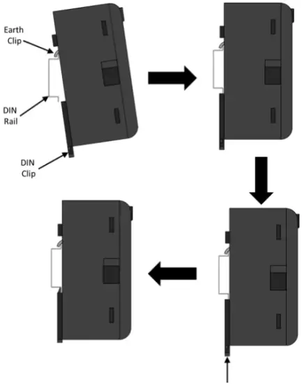
- Ensure that the installation area is free from any cables or wires that may get caught, and that there is enough space on the DIN rail to mount the module. Also ensure that the DIN clip underneath the module is in the open position.
- Place the module onto the DIN rail, hooking the metal earth clip underneath onto the rail first.
- Once the earth clip is hooked, push the bottom of the module onto the rail so that the module sits flat.
- Push the plastic DIN clip (located at the bottom of the module) upwards to lock and secure the module into position.
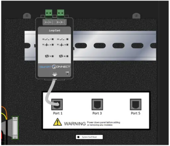
- Once the module is secured to the DIN rail, simply connect the supplied CAT5E cable to the module’s RJ45 port.
- Connect the other end of CAT5E cable to the nearest unoccupied RJ45 port on the termination PCB.
Trm Rj45 Port Address Designation
Each RJ45 port on the Smart Connect Multi-loop termination has its own unique port address. This port address is important to keep note of as it is displayed on Alarm/Fault messages and is used when configuring or setting up cause and effects on the panel (See SCM operation manual GLT-261-7-10).
Securing The Modules
The modules are designed to clip together to make them more secure. In addition, the SCM panel is supplied with Din rail stoppers. These should be fitted before the first module, and after the last module on each rail.
Before Powering The Panel On
- To prevent the risk of a spark, do not connect the batteries. Only connect the batteries after powering on the system from its main AC supply.
- Check that all external field wiring is clear from any open, shorts and ground faults.
- Check that all the modules have been installed properly, with correct connections and placement
- Check that all switches and jumper links are at their correct settings.
- Check that all interconnection cables are plugged in properly, and that they are secure.
- Check that the AC power wiring is correct.
- Ensure that the panel chassis has been correctly earth grounded.
Before powering on from the main AC supply, make sure that the front panel door is closed.
Power On Procedure
- After the above has been completed, turn the panel on (Via AC Only). The panel will follow the same power up sequence described in initial power up section above.
- The panel will now display one of the following messages.
| Message | Meaning |
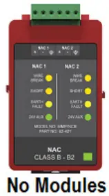 |
Panel has not detected any modules fitted during its power up check.
Power down the panel and check that the expected modules are fitted, and that all module cables are correctly inserted. Note that the panel will need at least one module fitted to run. |
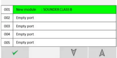 |
The panel has detected a new module added to a port that was previously empty.
This is the usual message seen the first time a panel is configured. |
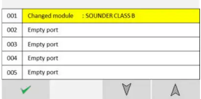 |
The panel has detected a different type of module fitted to a port that was previously occupied. |
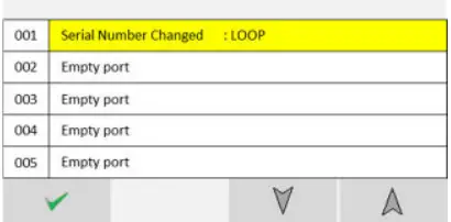 |
The panel has detected a module fitted to a port that is the same type, but its serial number has changed.
This could happen if a loop module was swapped with another one, for example. |
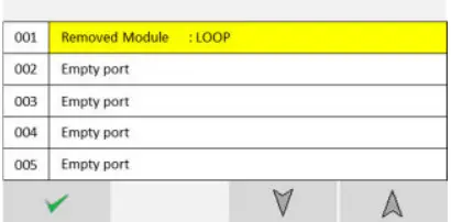 |
The panel has detected no module fitted to a port that was previously occupied. |
 |
The panel has detected no module changes, so has powered up and started running. |
- Check that the module configuration is as expected using the
 and
and  to navigate the through the port numbers. Press the
  icon to confirm the changes.
 - The new module is now configured into the panel and is ready for use.
- Since the batteries are not connected, the panel will report them as removed, lighting the yellow “Fault” LED, intermittently sounding the Fault buzzer, and displaying battery removed message on the screen.
- Connect the batteries, ensuring that the polarity is correct (Red wire = +ve) & (Black wire = -ve). Acknowledge the Fault event via the display screen, and reset the panel to clear the battery fault.
- The panel should now remain in the normal condition, and you can configure the panel as normal.
Field Wiring
![]() NOTE: The terminal blocks are removable to make wiring easier.
NOTE: The terminal blocks are removable to make wiring easier.
![]() ATTENTION: DO NOT EXCEED POWER SUPPLY RATINGS, OR MAXIMUM CURRENT RATINGS.
ATTENTION: DO NOT EXCEED POWER SUPPLY RATINGS, OR MAXIMUM CURRENT RATINGS.
Typical Wiring Diagram – Zeta Conventional Sounders

Typical Wiring Diagram – Bell Devices

![]() NOTE: When an ACM is configured as a bell output, the “24V On” LED on the front of the module will be flashing ON/OFF.
NOTE: When an ACM is configured as a bell output, the “24V On” LED on the front of the module will be flashing ON/OFF.
Typical Wiring Diagram (Auxiliary 24VDC) – External Equipment
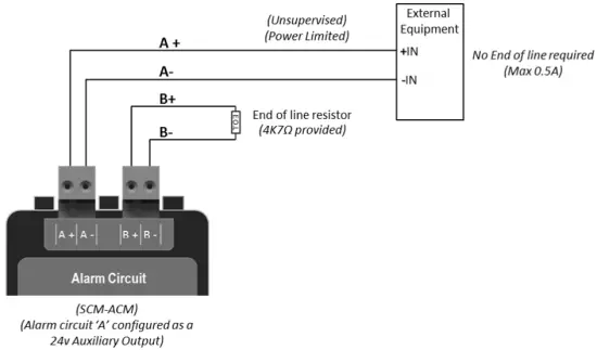
![]() NOTE: This wiring diagram demonstrates the option to program one or more SCM-ACM outputs to become a regulated constant 24VDC output.
NOTE: This wiring diagram demonstrates the option to program one or more SCM-ACM outputs to become a regulated constant 24VDC output.
![]() NOTE: When an alarm circuit is configured as a 24v aux output, the “24V On” LED on the front of the module will be.
NOTE: When an alarm circuit is configured as a 24v aux output, the “24V On” LED on the front of the module will be.
Wiring Recommendations
The SCM-ACM circuits are rated for 500mA each. The table shows the maximum wire run in metres for different wire gauges and alarm loads.
| Wire Gauge | 125mA Load | 250mA Load | 500mA Load |
| 18 AWG | 765 m | 510 m | 340 m |
| 16 AWG | 1530 m | 1020 m | 680 m |
| 14 AWG | 1869 m | 1246 m | 831 m |
![]() RECOMMENDED CABLE:
RECOMMENDED CABLE:
Cable should be BS approved FPL, FPLR, FPLP or equivalent.
Front Unit Led Indications
|
LED Indication |
Description |
 |
Flashing yellow when a wire break in the circuit is detected. |
 |
Flashing yellow when a short in the circuit is detected. |
|
|
Flashing green when the module is programmed as an unsynchronized bell output. Solid green when the module is programmed to provide a 24v auxiliary output. |
|
|
Pulses to show communication between the module and the motherboard. |


Specifications
| Specification | SCM-ACM |
| Design Standard | EN54-2 |
| Approval | LPCB (Pending) |
| Circuit Voltage | 29VDC Nominal (19V – 29V) |
| Circuit Type | Regulated 24V DC. Power limited & Supervised. |
| Maximum Alarm Circuit Current | 2 x 500mA |
| Maximum Aux 24V Current | 2 x 400mA |
| Maximum RMS current for a single sounder device | 350mA |
| Maximum Line Impedance | 3.6Ω total (1.8Ω per core) |
| Wiring Class | 2 x Class B [Power limited & Supervised] |
| End of Line Resistor | 4K7Ω |
| Recommended cable sizes | 18 AWG to 14 AWG (0.8mm2 to 2.5mm2 ) |
| Special Applications | 24V auxiliary voltage output |
| Operating Temperature | -5°C (23°F) to 40°C (104°F) |
| Max Humidity | 93% Non-Condensing |
| Size (mm) (HxWxD) | 105mm x 57mm x 47mm |
| Weight | 0.15KG |
Compatible Warning Devices
| Alarm Circuit Devices | |
| ZXT | Xtratone Conventional Wall Sounder |
| ZXTB | Xtratone Conventional Combined Wall Sounder Beacon |
| ZRP | Conventional Raptor Sounder |
| ZRPB | Conventional Raptor Sounder Beacon |
Maximum Warning Devices per Circuit
Some of the above warning devices have selectable settings for sound and beacon output. Please refer to the device manuals to calculate the maximum number allowed on each alarm circuit.


Documents / Resources
 |
Zeta SCM-ACM Smart Connect Multi Loop Alarm Circuit Module [pdf] Instruction Manual SCM-ACM Smart Connect Multi Loop Alarm Circuit Module, SCM-ACM, Smart Connect Multi Loop Alarm Circuit Module, Multi Loop Alarm Circuit Module, Alarm Circuit Module, Circuit Module, Module |


