![]() KCDL Chain Drive
KCDL Chain Drive
Instruction Manual
Introduction
All persons responsible for mounting, maintaining, cleaning and troubleshooting the chain drive must read, understand and heed the mounting instructions.
Keep these mounting instructions for later use. Changes are made in the interest of technical progress and are reserved.
The integration of the chain drive into the higher-level control is not described in these mounting instructions.
1.1 Notational conventions
Passages of these mounting instructions that require special attention or are a direct hazard warning are shown as follows.
1.1.1 Section-related warnings
![]() HAZARD This warning indicates a direct hazard which, unless avoided, involves a high risk of death or serious injury.
HAZARD This warning indicates a direct hazard which, unless avoided, involves a high risk of death or serious injury.
This warning indicates a direct hazard which, unless avoided, involves a high risk of death or serious injury.
![]() WARNING
WARNING
This warning indicates a hazard which, unless avoided, may involve a medium risk of death or serious injury.
![]() CAUTION
CAUTION
This warning indicates a hazard which, unless avoided, may involve a low risk of slight or medium injury.
NOTICE
This warning indicates a hazard which, unless avoided, may involve a low risk of material damage.
1.1.2 Other notational conventions
- Text following this mark represents an item in a list.
- Text following this mark describes action steps to be performed in the specified order.
- Text following this mark describes the result of the performed action steps.
1.1.3 Symbols used in the manual
| Fatal injury hazard due to electricity This symbol warns of a life-threatening electrical hazard. Touching live parts poses a direct risk of death. |
|
| Warning of crush hazard This symbol warns of the danger of injuries at body parts. The hands or other body parts can be crushed or otherwise injured. |
|
| Warning of hot surface This symbol warns of a burn hazard due to hot surfaces. |
|
| Observe information This symbol indicates that the information listed must be observed. |
Safety
2.1 Intended use
The chain drive KCDL is used to open and close windows for ventilation and smoke and heat extraction.
The chain drive may only be used in accordance with the listed functions and applications described in these mounting instructions. Unauthorised electrical and mechanical conversions and modifications to the chain drive are not permitted and will void the warranty and liability.
2.2Foreseeable misuse
Any use exceeding the concept of intended use and/or other use of the chain drive can lead to injuries or damages at the chain drive.
2.3 Personnel requirements
These instructions are intended for trained, competent and safety-conscious electrical specialists with know-ledge of mechanical and electrical equipment installation, accident prevention regulations and rules of the employers’ liability
insurance association.
2.4 General safety information
The following general safety instructions must always be observed:
- Mounting, maintenance, servicing and inspection may only be carried out by designated and trained specialist personnel.
- Read these instructions carefully before any mounting work.
- These instructions must be kept for later use.
- Observe the warnings in the individual chapters and before the instructions for action.
- The ambient temperatures specified in the technical data must be observed.
- At very high ambient temperatures or on facade or roof structures exposed to direct sunlight, the drives may heat up to such an extent that there is a risk of burns if touched.
Product description

The chain drive KCDL is a quiet, modular chain drive for opening and closing bottom-hung, top-hung, side-hung and roof windows. The chain drive is suitable for smoke/heat extraction and natural ventilation.
3.1 Special features
Simple sash or frame mounting with brackets that allow an opening angle of up to 50° for inward-opening bottom-hung windows and up to 80° for outward-opening top-hung windows.
The factory settings can be easily changed without the need for a PC tool. Configuration options are:
- Limit the opening width
- Search for zero position (closing position) again
- Plug-on function modules:
- 24 V DC ventilation
- 24 V DC SHE
Force 600 N in tension and compression (see Force-Distance diagram page 51)
OPEN and CLOSE indication, potential-free contacts integrated in the SHE function module Seal closure relief, adjustable
Automatic reversal in the “closing” direction (CLOSED) in case of overload
3.2 Transport and storage
The chain drive must only be transported and stored in its original packaging. It must not be knocked, dropped or
exposed to moisture, aggressive vapours or harmful environments.
Technical data
| Function module | KCDL ventilation DC | KCDL SHE | |
| Electrical features | |||
| Operating voltage | 24 V DC | ||
| Permissible operating voltage range | – 15 % 1+25 % | ||
| Permissible ripple of the nominal voltage | 2 Vss | ||
| Nominal current | 1.2 A | 1.5 A | |
| Standby power | 0 5 W | ||
| Cutoff current OPEN | 2.6 A | ||
| Cutoff current CLOSED | 2.6 A | ||
| Cutoff OPEN | Position detection | ||
| Cutoff CLOSED | Electronic cutoff | ||
| Protection class | III | ||
| Signal contact OPEN /CLOSED | -/- | 30 W resistive load, max. 1 A, 30 V DC, 24 V AC |
|
| Mechanical features | |||
| Stroke length | 400 mm, 600 mm, 800 mm, 1000 mm (limitable) | ||
| Pressing force | 600 N (Force-Distance diagram) | ||
| Tractive force | 600 N | ||
| Nominal tractive locking force | 3000 N | ||
| Lateral force | non-permissible | ||
| Running speed | Ventilation: 7 mm/s; SHE: 15 mm/s; pinch protection: < 5 mm/s With stroke 1000 mm, SHE:17 mm/s |
||
| Dimensions (with function modules) |
Stroke length in mm Stroke 400 Stroke 600 Stroke 800 Stroke 1000 |
(L x B x H in mm) 588 x 70 x 40 658×70 x40 728 x 70 x 40 798 x 70 x 40 |
(L x B x H in mm) 617 x 70 x 40 687×70 x40 757×70 x40 827x 70 x40 |
| Weight depending on stroke length | Stroke length in mm Stroke 400 Stroke 600 Stroke 800 Stroke 1000 |
Weight in kg approx. 2.8 approx. 3.2 approx. 3.5 approx. 3.9 |
|
| Function module | KCDL ventilation DC | KCDL SHE |
| Connection and operation | ||
| Connecting cable and interconnection | 2 x 1 mm2 + 4 x 0.25 mm’, L = 3 m, 5 m, 10 m | |
| Electrical connection | see Page 43 | |
| Pause time for change of direction of travel | t 100 ms | |
| Duty cycle | 30 % duty cycle referred to 10 min, 3 min ON, 7 min OFF | |
| Cycles’ | 6 | |
| Service life | maximum 10.000 cycles | |
| Multiple actuation against end position | permissible | |
| Maintenance | see Page 52 | |
| Installation and ambient conditions | ||
| Ambient temperature | -10 °C to +75 °C | |
| Protection rating | IP 20 | |
| Admissions and certificates | ||
| CE-compliant | yes | |
| TUV and UL certificate | on request | |
| Emission peak sound pressure level | LpA < 70(40) dB(A) | |
| Material | ||
| Housing | Aluminium | |
| Colour | Silver anodised EV1, special colours on request | |
| Opening mechanics | Steel chain with anti-corrosion coating | |
| End caps of the function modules | Black plastic | |
| Scope of delivery | lx basic drive KCDM 2x DC ventilation function module |
1x basic drive KCDM 1x DC ventilation function module lx SHE function module |
| Halogen-free | no | |
| Silicone-free | no | |
| RoHS-compliant | Yes | |
1 Number of OPEN / CLOSED cycles that may be run consecutively (without pause). Repetition of cycles after 1 hour.
Depending on the power controls used, higher currents must be expected in the start-up torque when dimensioning the cable cross-sections of the motor supply cables. Functionally reliable operation is guaranteed when connected to corresponding control systems from the same manufacturer. Conformity of functional reliability must be requested for operation on control systems from third party manufacturers.
Mounting variants and Mounting accessories
5.1 Mounting variants

5.2 Mounting accessories
| Bracket set; item number | For Mounting variant |
| Bracket set KCDL BS/IO; 13342504355 (black) 13342504351 (silver-grey) | Bottom-hung or side-hung window inward, sash mounting |
 |
 |
| Bracket set; item number | For Mounting variant |
| Bracket set KCDL BF/OO; 13342504365 (black) 13342504361 (silver-grey) | Top-hung window or roof window outward, frame mounting |
 |
 |
Mounting
![]() CAUTION
CAUTION
If the opening element is mounted ≤ 2.5 m above the finished floor, it must be checked whether an additional pinch protection system is required.
The mounting of the pinch protection system is described in the mounting instructions enclosed with the pinch protection system.
NOTICE
Mounting, maintenance, servicing and inspection must only be carried out by designated and trained specialist personnel. This is the only way to ensure that the product functions reliably.
6.1 Indications of hazards
![]() CAUTION
CAUTION
Danger of crushing body parts
Body parts can be crushed when closing the window.
When opening and closing the window, make sure that there are no persons near the window.
6.2 Sash mounting on bottom-hung or side-hung window inward with bracket set KCDL BS/IO
6.2.1 Minimum dimensions of the sash
 The following table shows the minimum dimensions of the sash as a function of the chain opening width (stroke) and the achievable opening angle (α).
| Stroke / mm | FB min / mm | FH min / mm | α / ° |
| 400 | 640 | 450 | 50 |
| 600 | 780 | 700 | 49 |
| 800 | 920 | 930 | 49 |
| 1000 | 1060 | 1150 | 50 |
Note: When installing on side-hung windows, please swap the sash height and width.
6.2.2 Bore dimensions for bracket set KCDL BS/IO

The dimension Y depends on the corresponding chain opening width of the drive.
Y = 266 mm for KCDL/400
Y = 336 mm for KCDL/600
Y = 406 mm for KCDL/800
Y = 476 mm for KCDL/1000
6.2.3 Mounting bracket set KCDL BS/IO

- Drill the 2 holes on the frame and the 4 holes on the sash.
- Fasten the hing bracket (1) with 2 rivet nuts M5 and 2 pan-head screws M5 x 16 (included in the bracket set KCDL BS/IO).
- Fasten the brackets (2) and (3) with 2 rivet nuts M5 and 2 pan-head screws M5 x 16 (included in the bracket set KCDL BS/IO).

- Insert the chain drive KCDL (4) into the brackets.

- Fasten the chain drive KCDL with one bolt with head and thread (1) and (2) Ø5 x 30/M5 x 5 (included in the bracket set KCDL BS/IO) on the left and right side.

- Place the function module on both sides of the chain drive KCDM and fasten it with one screw each(1)and (2).

- Slide the two covers (1) over the recesses.

- Energise the drive in the OPEN direction (see chapter “Electrical connection”, Page 43).
- Extend the chain.
- Connect the chain end to the hinge bracket. Push the cylindrical pin (1) Ø5 x 65 (included in the bracket set KCDL BS/IO) sideways into the hinge bracket.
- Press in the two rubber buffers (2) (included in the bracket set KCDL BS/IO) at the front of the hinge bracket to fix the cylindrical pin.

6.3 Frame mounting on top-hung or roof window outward, with bracket set KCDL BF/OO
6.3.1 Minimum dimensions of the sash

The following table shows the minimum dimensions of the sash as a function of the chain opening width
(stroke) and the achievable opening angle (α).
| Hub/mm | FB min / mm | FH min / mm | α / ° |
| 400 | 640 | 350 | 78 |
| 600 | 780 | 500 | 81 |
| 800 | 920 | 650 | 82 |
| 1000 | 1060 | 800 | 83 |
6.3.2 Bore dimensions for bracket set KCDL BF/OO

The dimension Y depends on the corresponding chain opening width of the drive.
Y = 251 mm for KCDL/400
Y = 321 mm for KCDL/600
Y = 391 mm for KCDL/800
Y = 461 mm for KCDL/1000
6.3.3 Mounting bracket set KCDL BF/OO

- After marking the holes, drill the 8 holes on the frame and the 2 holes on the sash.
- Fasten the hing bracket (1) with 2 rivet nuts M5 and 2 pan-head screws M5 x 16 (included in the bracket set KCDL BF/OO).
- Fasten the brackets (2) and (3) with 4 rivet nuts M5 and 4 pan-head screws M5 x 16 (included in the bracket set KCDL BF/OO).

- Insert the chain drive KCDL (4) into the brackets.

- Fasten the chain drive KCDL with one bolt with head and thread (1) and (2) Ø 5 x 3/M5 x 5 (included in the bracket set KCDL BF/OO) on the left and right side.

- Place the function module on both sides of the chain drive KCDM and fasten it with one screw each (1) and (2).

- Slide the two Covers KCDL BF/OO (1) over the recesses.

- Energise the drive in the OPEN direction (see chapter “Electrical connection”, Page 43).
- Extend the chain.
- Connect the chain end piece to the hinge bracket.
Push the cylindrical pin (1) Ø 5 x 65 (included in the bracket set KCDL BF/OO) sideways into the hinge bracket. - Press in the two rubber buffers (2) (included in the bracket set KCDL BF/OO) at the front of the hinge bracket to fix the cylindrical pin.
Electrical connection
7.1 Electrical connection of DC ventilation function module
NOTICE
Wiring and electrical connection, as well as the replacement of power supply lines, may only be carried out by an authorised electrician (connection type Y according to DIN EN 60335-1:2020-08). The connecting cables must not be subjected to tension, torsion, crushing or shearing.
7.1.1 Electrical connection to the DC ventilation board
 DC ventilation function module

- Pull the housing profile (1) off the DC Ventilation function module in the direction of the arrow.

- Insert the wires (1) into the plug-in terminals.
Colour assignment and function: See illustration below. Colour assignment and function of the power cable
No. Function Wire crossection Wire colour 1.24 V 0 V 1 mm2 white 2.0 V 24 V 1 mm’ brown 3.Communication A 0.25 mm2 green 4.Communication B 1 0.25 mm2 yellow
7.1.2 Mounting the strain relief for the power cable

- DC ventilation function module
- Clamp for strain relief
- Screws for attaching the clamp
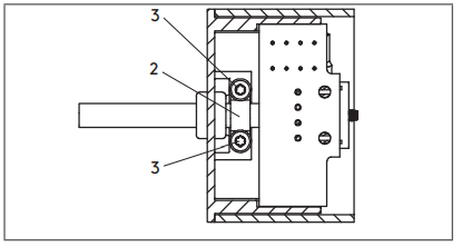 Turn the function module over so that the bottom is facing upwards.
Fasten the clamp (2) to the bottom of the DC Push the housing profile (1) onto the DC ventilation function module (2) in the direction of the arrow.
 Connect the DC ventilation function module (1) to the drive (2) and screw it tight.
7.2 Electrical connection of SHE function module
NOTICE
Wiring and electrical connection, as well as the replacement of power supply lines, may only be carried out by an authorised electrician (connection type Y according to DIN EN 60335-1:2020-08). The connecting cables must not be subjected to tension, torsion, crushing or shearing.
NOTICE If the SHE function module is used subsequently, the drives must be configured.
7.2.1 Electrical connection to the SHE board
 Pull the housing profile (1) off the SHE function module in the direction of the arrow.
- Insert the wires into the plug-in terminals (2). Colour assignment and function: See illustration below
 Colour assignment and function of the power cable
No. Function Wire cross-section Wire colour 1. 124 V OV 1mm² white 2. OV 24 V 1mm ² brown 3. Communication A 0.25mm² not used 4. Communication B 0.25mm² not used 5. Highspeed-In SHE 0.25mm² pink 6. Signal contact OPEN 0.25mm² yellow 7. COM 0.25mm² grey 8. Signal contact Green CLOSED 0.25mm² Green
* Connection for wire 5 (pink), Highspeed-In SHE (+24 V), in control panels from Kingspan STG GmbH to the red LED (activation) terminal from the SHE manual call point.
| Control panels | Terminal no. |
| TRZ Plus 2A, TRZ Plus 2A Comfort | 14 |
| Compact control panel 2A | 14 |
| Compact control panel 4A/8A | 12 |
| RDA Compact control panel 8A | 12 |
| Module control panel MZ3 | 3 (RM-Modul) |
| EasyConnect 20A, EasyConnect+ | 4 |
| EMZ 48V | 6 |
7.2.2 Mounting the strain relief for the power cable

- DC ventilation function module
- Clamp for strain relief
- Screws for attaching the clamp

- Turn the function module over so that the bottom is facing upwards.
- Fasten the clamp (2) to the bottom of the SHE function module with the two screws (3).

- Push the housing profile (1) onto the SHE function module (2) in the direction of the arrow.

- Connect the SHE function module (1) to the drive (2) and screw it tight.
7.3 Connection example for 2 x KCDL, 1 x SHE function module and 1 x locking drive type KLML

Manual configuration/commissioning
![]() CAUTION
CAUTION
![]() Danger of crushing body parts
Danger of crushing body parts
Body parts can be crushed when closing the window.
When opening and closing the window, make sure that there are no persons near the window.
NOTICE
The drives are configured as individual drives at the factory. Manual configuration is necessary (to connect / synchronise several drives) and is only possible on the DC ventilation function module.
The following configurations can be set using it:
- Connecting and synchronising chain and dead bolt drives with each other
- Teaching the zero position (= sash closed)
- Limiting the opening width
- Setting the pinch protection range
NOTICE
The opening width in SHE mode is basically the same as the opening width configured for ventilation mode.
8.1 Connecting and searching for zero position
- If there are several drives on one sash: Connect the drives electrically to each other using the interconnection.
- Connect the connecting cable to the DC ventilation function module of the drive. Configuration via the SHE module is NOT possible.
- Connect the power supply (24 V DC with pole reversal function) of the connecting cable (white and brown wire).
The following illustration shows the connection of the jumper wire for configuring the drives.
| Structure chart/configuration sequence | Step | Sequence of actions |
 |
Step 1 Step 2 Step 3 Step 4 Step 5 Step 6 Step 7 Step 8 Step 9 Step 10 |
►Apply voltage in the OPEN direction (for example, an OPEN command via a ventilation button). ▷ The drives start to extend the chain. ► Connect the green wire (communication A) and the white wire (24 V) of the connecting cable with a jumper wire for approx. 1 second. ▷ The drives stop for 6 to 9 seconds (the drive set is formed). ►Then move slowly in the CLOSED direction until the sash is closed. ▷ This position is saved as the zero position. ►Then move slowly in the OPEN direction. ATTENTION :If NO opening width limitation is desired, the chain must be extended to the maximum. Limiting the opening width ► When the desired opening width is reached, interrupt the voltage (e.g. by a STOP command via a ventilation button). ► Apply voltage in the CLOSED direction (e.g. by a CLOSED command via a ventilation button). ▷ The drives save the achieved opening width and slowly move in the CLOSED direction. If no pinch protection range is to be defined, steps 8 and 9 are omitted. ► Allow the drive set to close completely. Setting the pinch protection range ► From the chain position at which the drives are to slow down their approach, apply a voltage in the OPEN direction (e.g. by an OPEN command via a ventilation button). ▷ The drives stop and remember this position as the start position for the decelerated pproach. ►Apply voltage in the CLOSED direction (e.g. by a CLOSED command via a ventilation button). ▷ The drives move slowly in the CLOSED direction until the sash is closed (zero position). ▷ The configuration is completed when the CLOSED position is reached. |
Drawing
9.1 Drawing with DC ventilation function module

| Drive type /stroke length | Dimension A /mm | Dimension B /mm |
| KCDL/400 | 588 | 266 |
| KCDL/600 | 658 | 336 |
| KCDL/800 | 728 | 406 |
| KCDL/1000 | 798 | 476 |
9.2 Drawing with SHE function module

| Drive type /stroke length | Dimension A /mm | Dimension B /mm |
| KCDL/400 | 617 | 266 |
| KCDL/600 | 687 | 336 |
| KCDL/800 | 757 | 406 |
| KCDL/1000 | 827 | 476 |
Force-Distance diagram

Fault
If a safe operation is no longer possible, take the chain drive out of operation.
Safe operation may not be possible under the following circumstances:
- The chain drive is damaged.
- The chain drive no longer functions.
- The chain drive has been stored under unfavourable conditions for a longer period of time.
Fault Cause Measure The window does not open or close. No power supply available. Chain drive defective. Check the power supply of the chain drive.
Check the line lengths and cross-sections
Check that the chain drive is connected correctly.
Maintenance/cleaning
![]() HAZARD
HAZARD
![]() Fatal injury hazard due to electric shock
Fatal injury hazard due to electric shock
Touching live parts may result in a fatal electric shock.
- Before starting maintenance work, switch off the power supply and secure it against being switched on.
![]() CAUTION
CAUTION
![]() Danger of crushing body parts
Danger of crushing body parts
Body parts can be crushed when closing the window.
When opening and closing the window, make sure that there are no persons near the window.
![]() CAUTION
CAUTION
Burn hazard due to hot surfaces
![]() At very high ambient temperatures or on facade or roof structures exposed to direct sunlight, the drives may heat up to such an extent that there is a risk of burns if touched.
At very high ambient temperatures or on facade or roof structures exposed to direct sunlight, the drives may heat up to such an extent that there is a risk of burns if touched.
- Always wear safety gloves when working near hot parts.
- Before maintenance work, let the chain drive cool down to the ambient temperature.
NOTICE
Maintenance work is only allowed to be done by skilled personnel.
- Visual inspection for damage
- Check the mechanical fastenings of the chain drive (check screws for tightness).
- Check the chain drive for damage and dirt
Clean the chain drive with a soft, dry and lint-free cloth. In case of heavier soiling, clean with a cloth slightly moistened with lukewarm water. Do not use cleaners containing solvents, as this will damage the surface.
The chain itself must NOT be cleaned wet. - Check correct functioning of the chain drive
- Check guards for entrapment protection
Dismantling/disposal
Dismantling is carried out in reverse order to mounting.
![]() Packaging
Packaging
The product is packaged to protect it from transport damage. The packaging material can be disposed of in an environmentally friendly manner and r ecycled properly.
Disposal must be carried out in accordance with the valid legal regulations of the respective country.
Information on disposal can be obtained from your city or local government.
![]() Product
Product
At the end of its service life, the product can be disposed of in an environmentally friendly manner and recycled properly.
Disposal of the product must be carried out in accordance with the valid legal regulations of the respective country.
Information on disposal can be obtained from your city or local government.
Documents / Resources
 |
Windowdrives KCDL Chain Drive [pdf] Instruction Manual KCDL Chain Drive, KCDL, Chain Drive, Drive |


