Value Testers LevelPro ShoPro SP100 Level Display Controller
Specifications
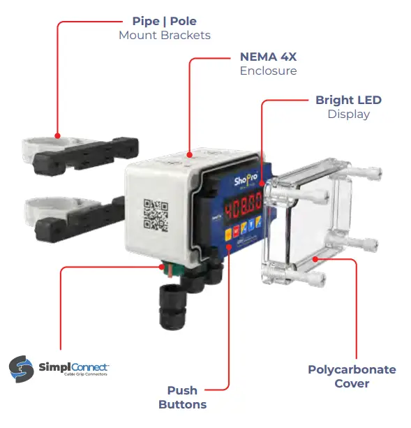
- Product Name: Level Display | Controller
- Mounting: Pipe | Pole Mount Brackets
- Enclosure: NEMA 4X
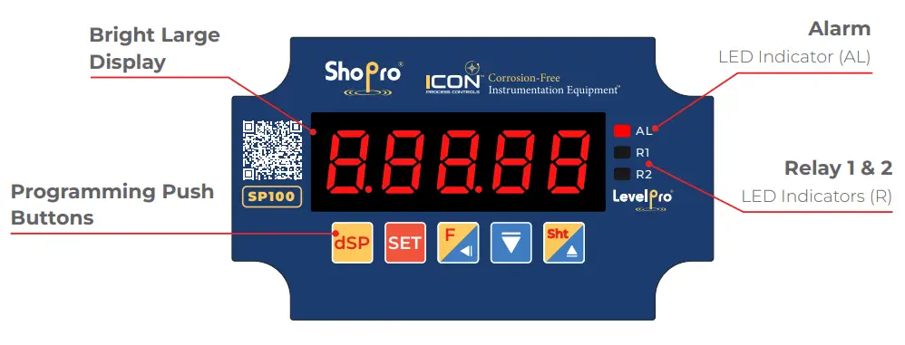
- Display: Bright LED Display
- Environment: Designed for industrial applications, resistant to corrosive environments
- Output Options: Multiple
Product Usage Instructions
Safety Information
Before using the unit, ensure you follow these safety guidelines:
- De-pressurize and vent system prior to installation or removal.
- Confirm chemical compatibility before use.
- Do NOT exceed maximum temperature or pressure specifications.
- ALWAYS wear safety goggles or face-shield during installation and/or service.
- Do NOT alter product construction.
User Safety Instructions
Follow these guidelines for safe and proper usage of the unit:
- Avoid using the unit in areas with excessive shocks, vibrations, dust, humidity, corrosive gases, or oils.
- Avoid areas with explosion risks.
- Avoid areas with significant temperature variations, condensation, ice, or direct sunlight exposure.
- Maintain ambient temperature within recommended values; consider forced cooling if needed.
- Ensure proper installation by qualified personnel adhering to safety regulations.
- Connect GND input to PE wire.
- Properly configure the unit for its application to avoid operational issues or accidents.
- Use additional safety systems in case of unit malfunction posing serious threats.
- Switch off and disconnect power supply before troubleshooting malfunctions.
- Ensure neighboring equipment meets safety standards and regulations.
- Do not attempt self-repairs; submit defective units for repairs at authorized service centers.
Usage Environment
The unit is designed for industrial environments and should not be used in household settings or similar environments. It is suitable for harsh corrosive conditions.
Frequently Asked Questions (FAQ)
Q: Can the unit be used in household environments?
A: No, the unit is designed for industrial applications and should not be used in household settings.
Q: What should I do if the unit malfunctions?
A: In case of malfunction, switch off the unit, disconnect it from power, and contact an authorized service center for repairs. Do not attempt to repair it yourself.
Q: How should I ensure user safety when using the unit?
A: Follow all safety guidelines provided in the user manual, including proper installation, environmental considerations, and adherence to recommended procedures.
Safety Information
- De-pressurize and vent system prior to installation or removal!
- Confirm chemical compatibility before use!
- DO NOT exceed maximum temperature or pressure specifications!
- ALWAYS wear safety goggles or face-shield during installation and/or service!
- DO NOT alter product construction!
Warning | Caution | Danger
Indicates a potential hazard. Failure to follow all warnings may lead to equipment damage, or failure, injury, or death.
Note | Technical Notes
Highlights additional information or detailed procedure.
Basic Requirements & User Safety
- Do not use the unit in areas threatened with excessive shocks, vibrations, dust, humidity, corrosive gasses and oils.
- Do not use the unit in areas where there is risk of explosions.
- Do not use the unit in areas with significant temperature variations, exposure to condensation or ice.
- Do not use the unit in areas exposed to direct sunlight.
- Make sure that the ambient temperature (e.g. inside the control box) does not exceed the recommended values. In such cases forced cooling of the unit must be considered (e.g. by using a ventilator).
- The manufacturer is not responsible for any damages caused by inappropriate installation, not maintaining the proper environmental conditions and using the unit contrary to its assignment.
- Installation should be conducted by qualified personnel . During installation all available safety requirements should be considered. The fitter is responsible for executing the installation according to this manual, local safety and EMC regulations.
- GND input of device should be connected to PE wire.
- The unit must be properly set-up, according to the application. Incorrect configuration can cause defective operation, which can lead to unit damage or an accident.
- If in the case of a unit malfunction there is a risk of a serious threat to the safety of people or property additional, independent systems and solutions to prevent such a threat must be used.
- The unit uses dangerous voltage that can cause a lethal accident. The unit must be switched off and disconnected from the power supply prior to starting installation of troubleshooting (in the case of malfunction).
- Neighboring and connected equipment must meet the appropriate standards and regulations concerning safety and be equipped with adequate overvoltage and interference filters.
- Do not attempt to disassemble, repair or modify the unit yourself. The unit has no user serviceable parts. Defective units must be disconnected and submitted for repairs at an authorized service center.
The unit is designed for operation in an industrial environment and must not be used in a household environment or similar.
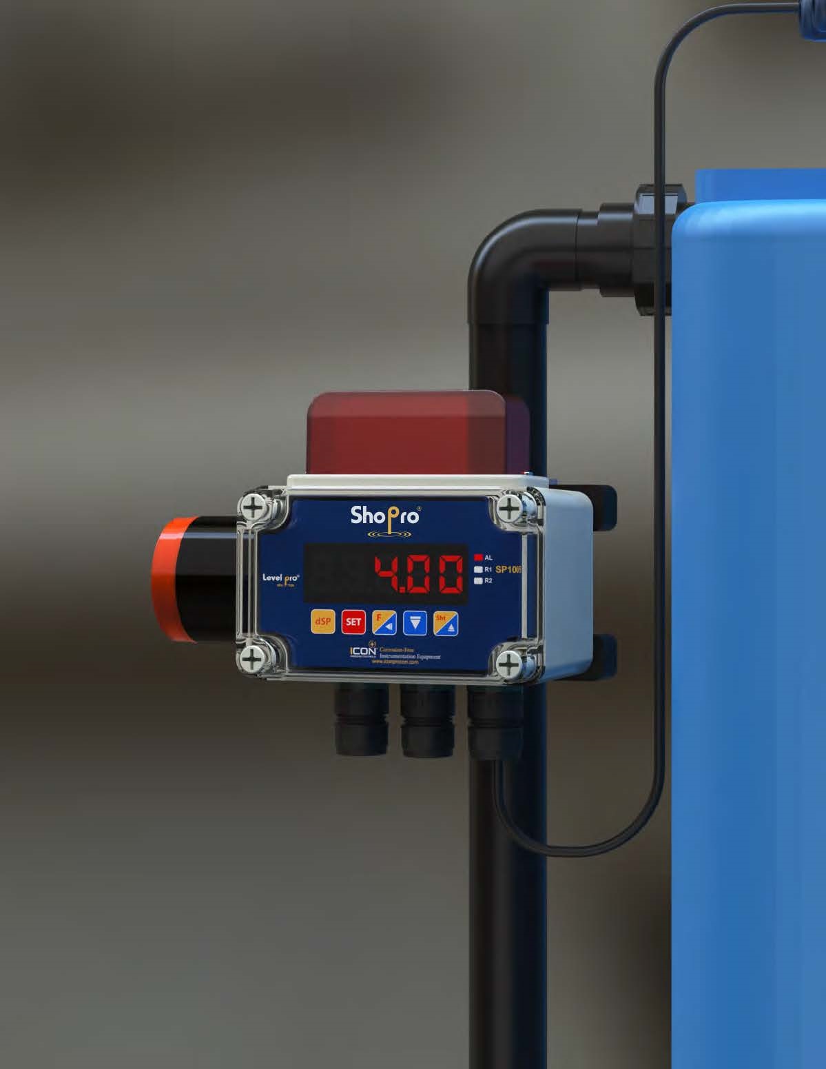
The ShoPro® Series Level Display | Controller is engineered to be the most durable and dependable wall or pipe-mount remote display in the industry. This all-in-one unit is ready to use straight out of the box, featuring a bright LED display, NEMA 4X enclosure, polycarbonate cover, cord grips, and plastic captive screws.
Designed for industrial applications, it withstands even the harshest corrosive environments and is available with multiple output options.
Features
- All-in-one | Out of the Box Ready to Use
- Visual Alarm — High | Low Level
- NEMA 4X Enclosure
- Corrosion Resistant Thermoplastic
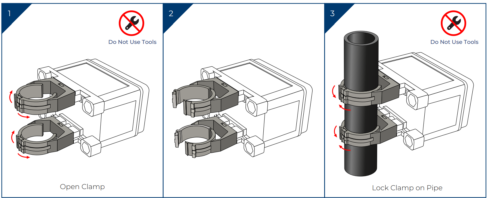
- Cord Grips Included – No Tools Required
Model Selection
| ShoPro® SP100 — Liquid Level LED Display | ||
| Part Number | Input | Output |
| SP100 | 4-20mA | 4-20mA |
| SP100-A | 4-20mA | 2 Relay + 4-20mA + Audible |
| SP100-V | 4-20mA | 2 Relay + 4-20mA + Visual |
| SP100-A-V | 4-20mA | 2 Relay + 4-20mA + Audible & Visual |
Technical Specifications
| General | |
| Display | LED | 5 x 13mm High | Red |
| Displayed Values | -19999 ~ 19999 |
| Transmission Parameters | 1200…115200 bit/s, 8N1 / 8N2 |
| Stability | 50 ppm | °C |
| Housing Material | Polycarbonate |
| Protection Class | NEMA 4X | IP67 |
| Input Signal | Supply | |
| Standard | Current: 4-20mA |
| Voltage | 85 – 260V AC/DC | 16 – 35V AC, 19 – 50V DC* |
| Output Signal | Supply | |
| Standard | 4-20mA | 2 x Relays (5A) + 4-20mA |
| Voltage | 24VDC |
| Passive Current Output * | 4-20mA | (Operating Range Max. 2.8 – 24mA) |
| Performance | |
| Accuracy | 0.1% @ 25°C One Digit |
| Accuracy According to IEC 60770 – Limit Point Adjustment | Non-Linearity | Hysteresis | Repeatability | |
| Temperatures | |
| Operating Temperatures | -20 to 158°F | -29 to 70°C |
Installation Instructions
The unit has been designed and manufactured in a way assuring a high level of user safety and resistance to interference occurring in a typical industrial environment. In order to take full advantage of these characteristics installation of the unit must be conducted correctly and according to the local regulations.
- Read the basic safety requirements on page 2 prior to starting the installation.
- Ensure that the power supply network voltage corresponds to the nominal voltage stated on the unit’s identification label.
The load must correspond to the requirements listed in the technical data. - All installation works must be conducted with a disconnected power supply.
- Protecting the power supply connections against unauthorized persons must be taken into consideration.
Package Contents
Please verify that all listed parts are consistent, undamaged and included in the delivery / your specified order. After removing the unit from the protective packaging, please verify that all listed parts are consistent, undamaged and included in the delivery/your specified order.
Any transportation damage must be immediately reported to the carrier. Also, write down the unit serial number located on the housing and report the damage to the manufacturer.
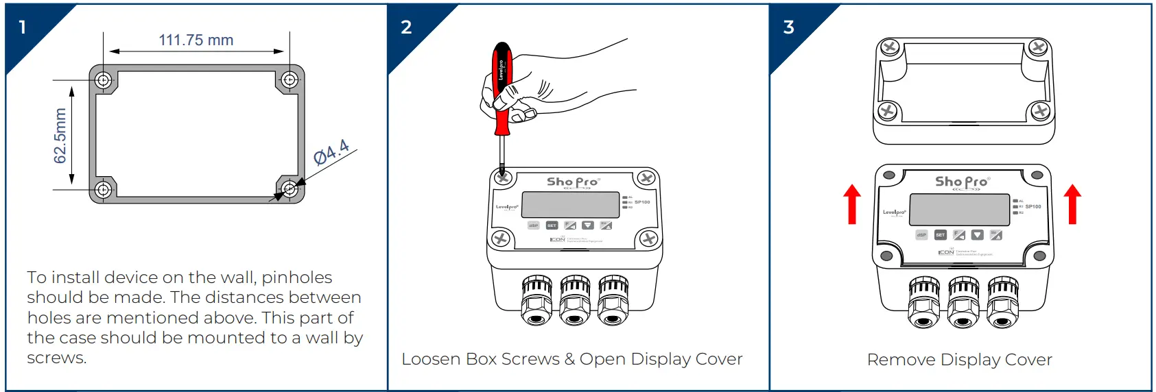
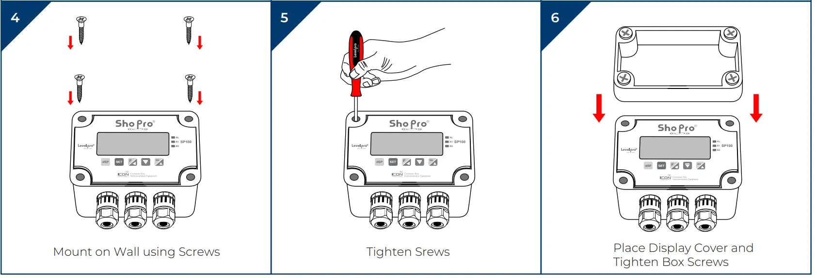
Wall Mounting
Pipe | Pole Clamp Installation
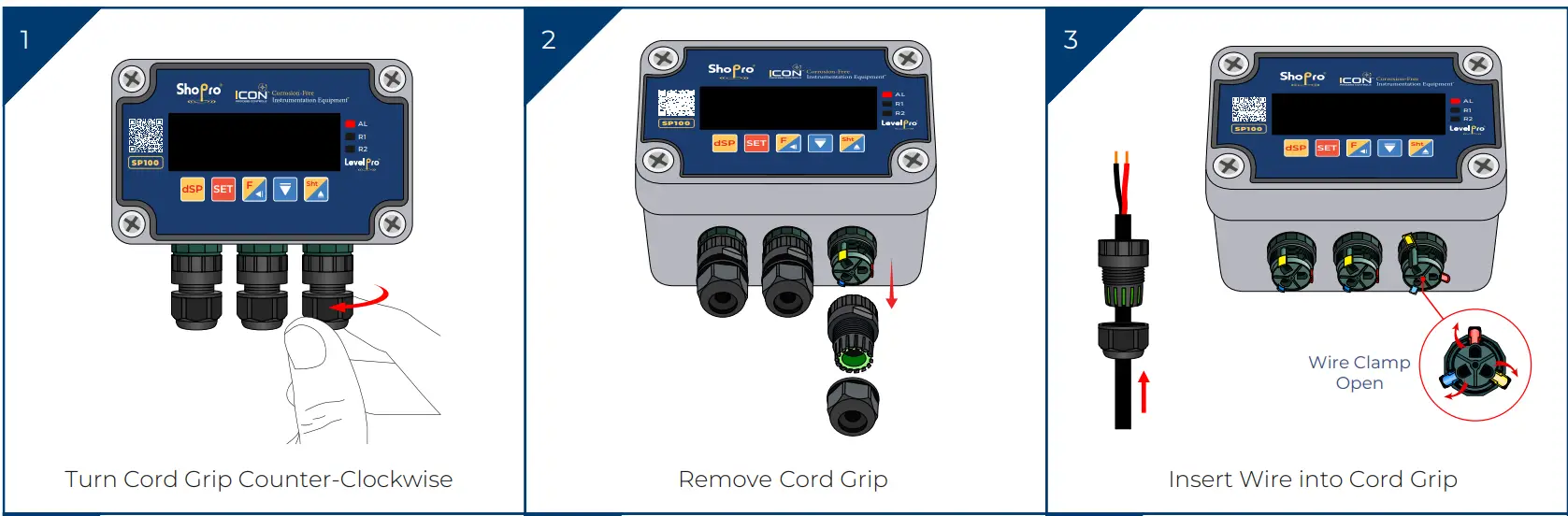
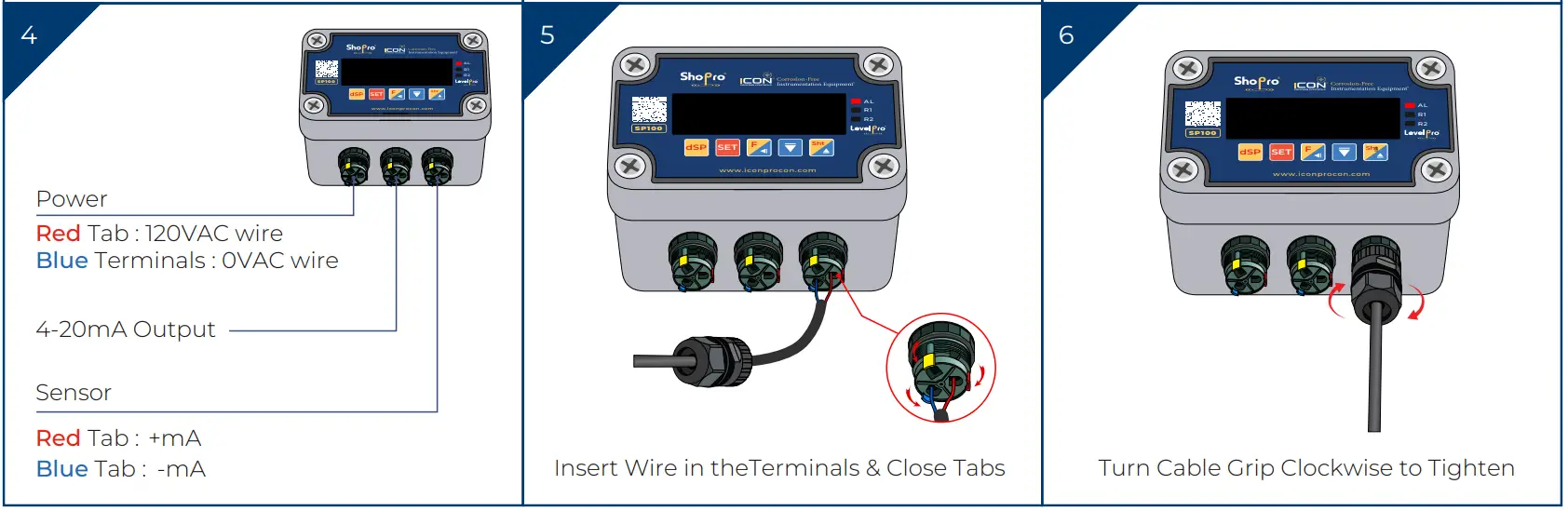
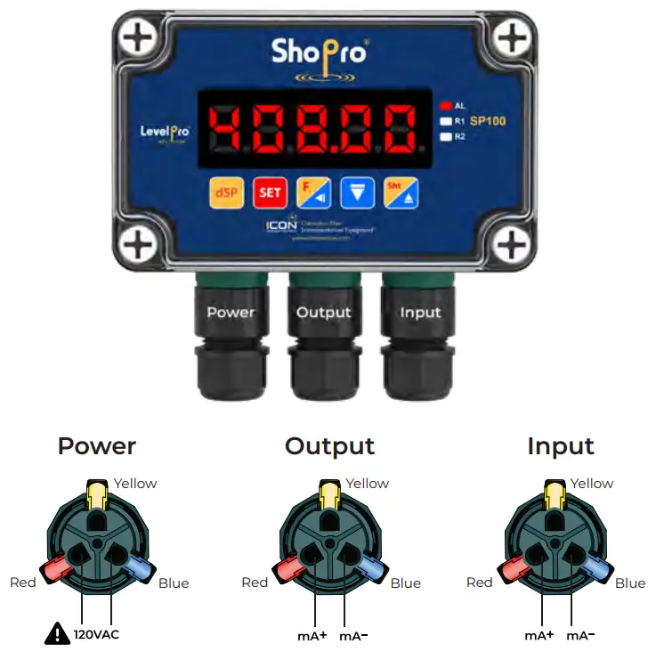
Wiring
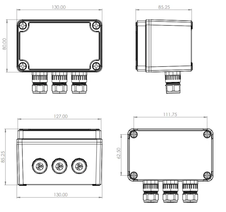
Dimensions
Wiring Diagram
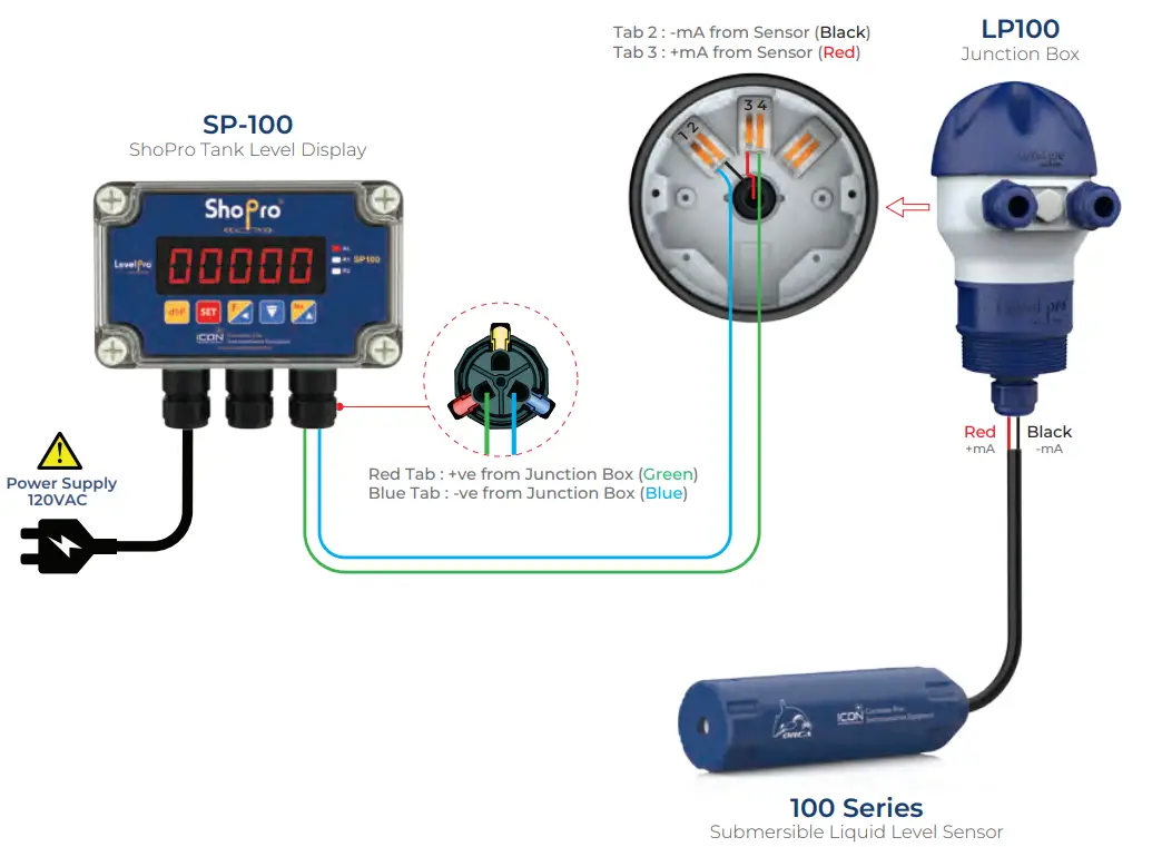
Wiring – ShoPro + 100 Series Submersible Level Sensor
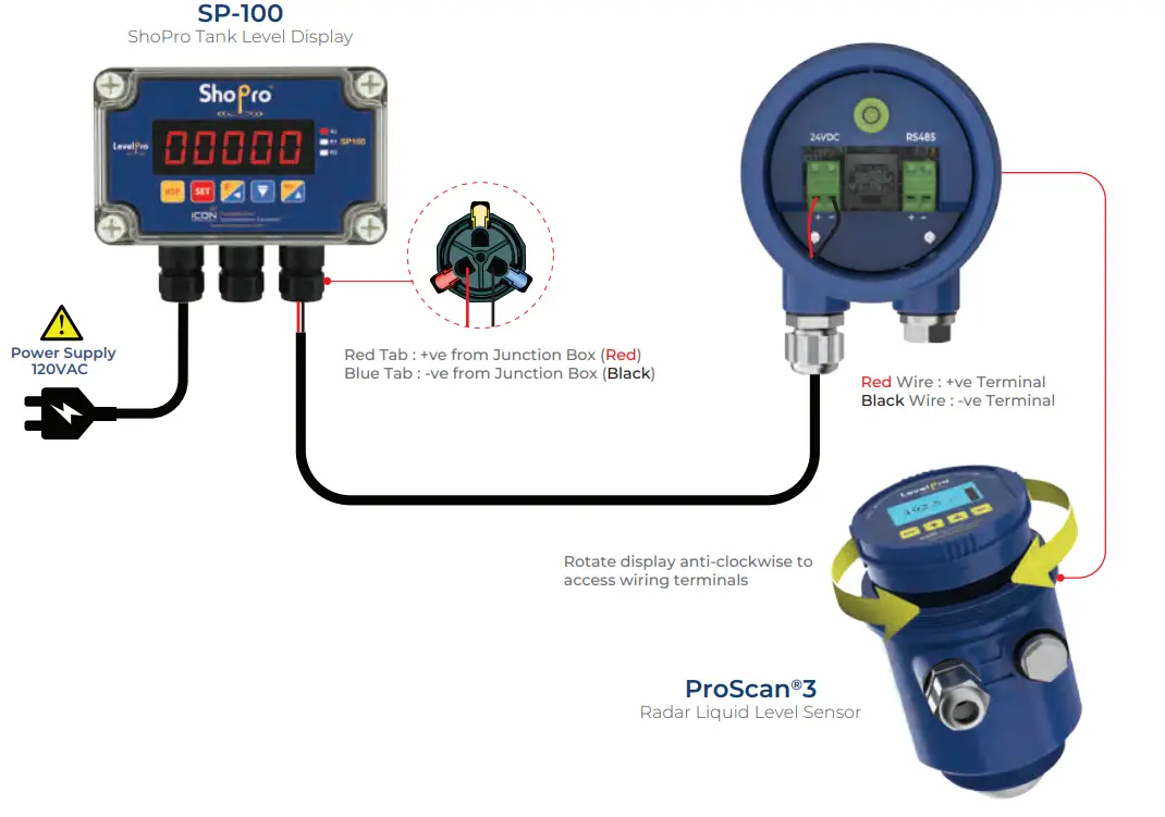
Wiring – ShoPro + ProScan®3 Radar Level Sensor
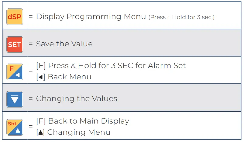
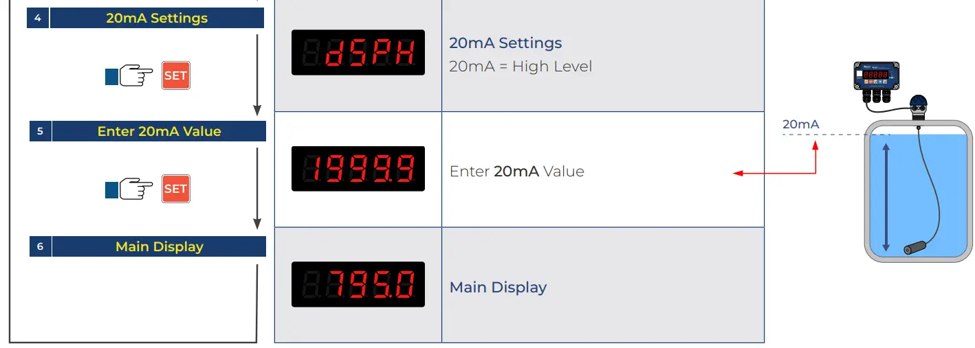
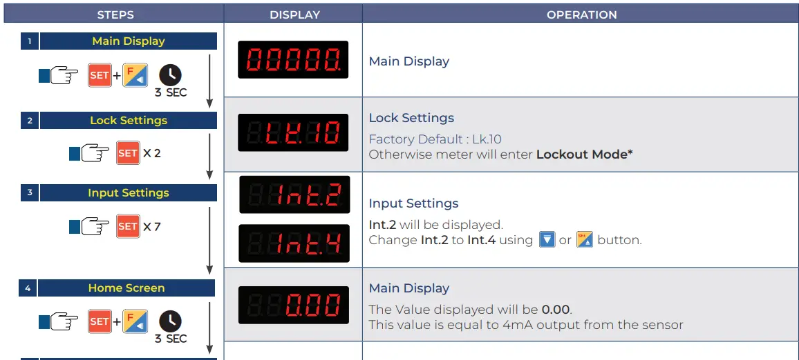
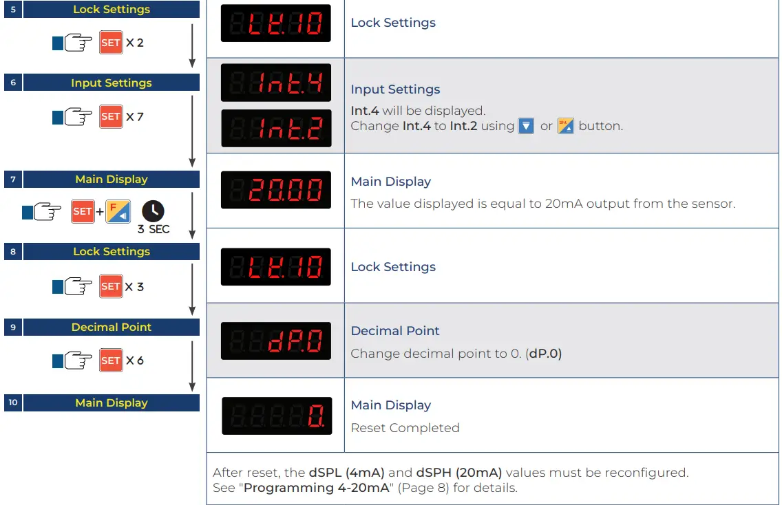
Programming 4-20mA
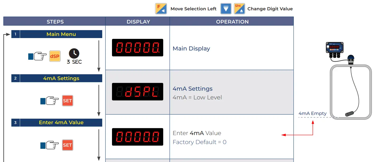
- dSPL = Low Level Value | Empty or Lowest Liquid Level | Factory Default = 0.
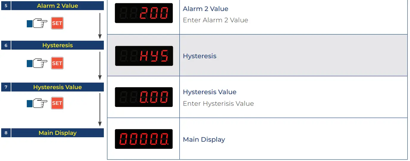
- Alarm ProgrammingdSPH = High Level Value | Enter Maximum Level.
Alarm Programming
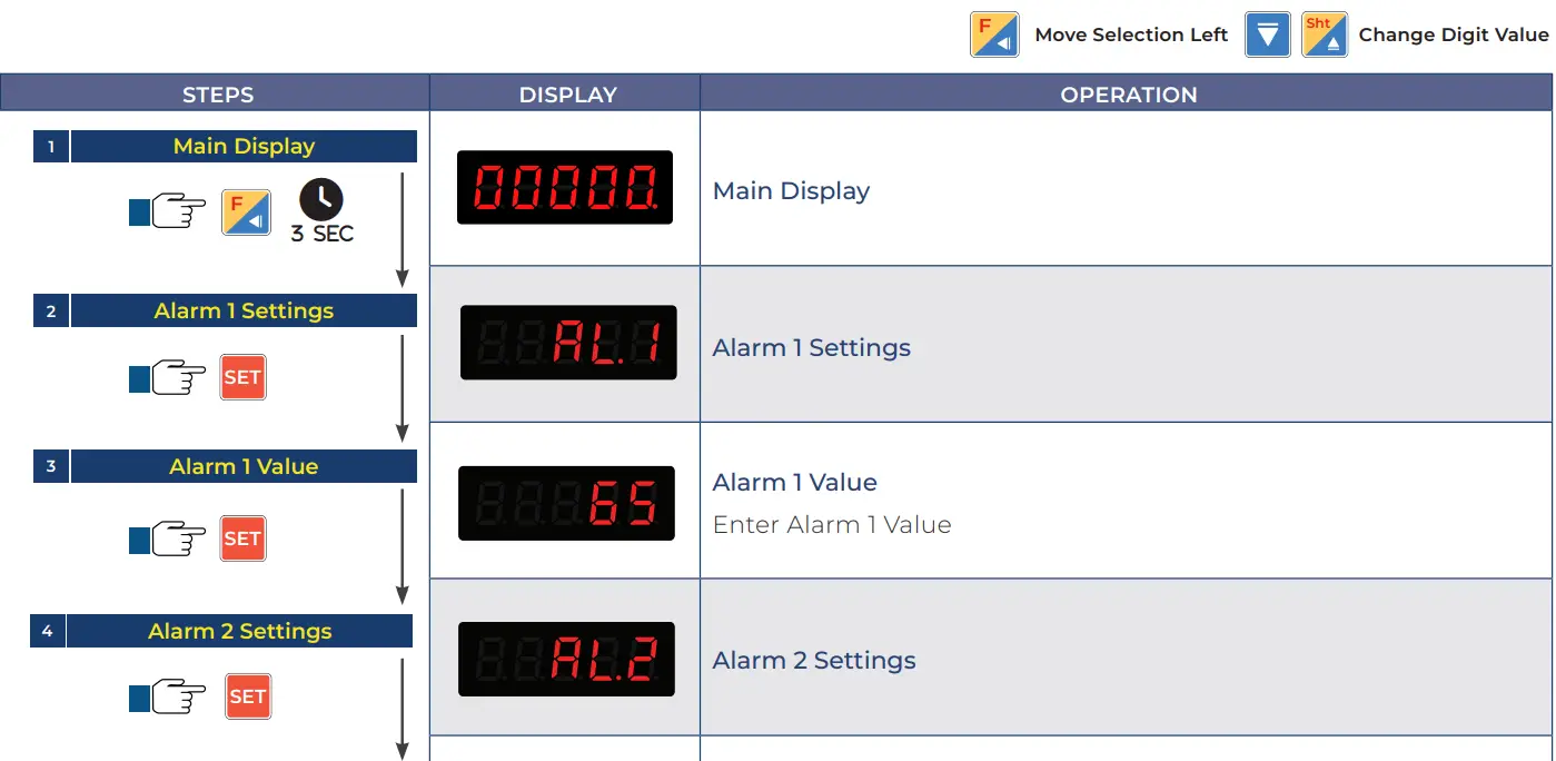
Alarm Mode Selection
| ALt No. | Description | |
| ALt = 1 |
|
|
| ALt = 2 |
|
|
| ALt = 3 |
|
|
| CV = Current Value | ||
Note:
To access the Alarm Mode Selection Menu, press
Reset Programming
Warranty, Returns and Limitations
Warranty
Icon Process Controls Ltd warrants to the original purchaser of its products that such products will be free from defects in material and workmanship under normal use and service in accordance with instructions furnished by Icon Process Controls Ltd for a period of one year from the date of sale of such products. Icon Process Controls Ltd obligation under this warranty is solely and exclusively limited to the repair or replacement, at Icon Process Controls Ltd option, of the products or components, which Icon Process Controls Ltd examination determines to its satisfaction to be defective in material or workmanship within the warranty period. Icon Process Controls Ltd must be notified pursuant to the instructions below of any claim under this warranty within thirty (30) days of any claimed lack of conformity of the product. Any product repaired under this warranty will be warranted only for the remainder of the original warranty period. Any product provided as a replacement under this warranty will be warranted for the one year from the date of replacement.
Returns
Products cannot be returned to Icon Process Controls Ltd without prior authorization. To return a product that is thought to be defective submit a customer return (MRA) request form and follow the instructions therein. All warranty and non-warranty product returns to Icon Process Controls Ltd must be shipped prepaid and insured. Icon Process Controls Ltd will not be responsible for any products lost or damaged in shipment.
Limitations
This warranty does not apply to products which: 1) are beyond the warranty period or are products for which the original purchaser does not follow the warranty procedures outlined above; 2) have been subjected to electrical, mechanical or chemical damage due to improper, accidental or negligent use; 3) have been modified or altered; 4) anyone other than service personnel authorized by Icon Process Controls Ltd have attempted to repair; 5) have been involved in accidents or natural disasters; or 6) are damaged during return shipment to Icon Process Controls Ltd reserves the right to unilaterally waive this warranty and dispose of any product returned to Icon Process Controls Ltd where: 1) there is evidence of a potentially hazardous material present with the product; or 2) the product has remained unclaimed at Icon Process Controls Ltd for more than 30 days after Icon Process Controls Ltd has dutifully requested disposition. This warranty contains the sole express warranty made by Icon Process Controls Ltd in connection with its products.
ALL IMPLIED WARRANTIES, INCLUDING WITHOUT LIMITATION, THE WARRANTIES OF MERCHANTABILITY AND FITNESS FOR A PARTICULAR PURPOSE, ARE EXPRESSLY DISCLAIMED. The remedies of repair or replacement as stated above are the exclusive remedies for the breach of this warranty. IN NO EVENT SHALL Icon Process Controls Ltd BE LIABLE FOR ANY INCIDENTAL OR CONSEQUENTIAL DAMAGES OF ANY KIND INCLUDING PERSONAL OR REAL PROPERTY OR FOR INJURY TO ANY PERSON. THIS WARRANTY CONSTITUTES THE FINAL, COMPLETE AND EXCLUSIVE STATEMENT OF WARRANTY TERMS AND NO PERSON IS AUTHORIZED TO MAKE ANY OTHER WARRANTIES OR REPRESENTATIONS ON BEHALF OF Icon Process Controls Ltd. This warranty will be interpreted pursuant to the laws of the province of Ontario, Canada.
If any portion of this warranty is held to be invalid or unenforceable for any reason, such finding will not invalidate any other provision of this warranty.
24-0547 © Icon ProcFind Quality Products Onliness Controls Ltd. e at:
Valuetesters.com
info@valuetesters.com
Documents / Resources
 |
Value Testers LevelPro ShoPro SP100 Level Display Controller [pdf] Instruction Manual sp100-v, LevelPro ShoPro SP100 Level Display Controller, LevelPro ShoPro SP100, Level Display Controller, Display Controller, Controller |

