Uplink PC1616 Alarm Cellular Communicators and Programming the Panel
CAUTION
- It is advised that an experienced alarm installer programs the panel as further programming may be required to ensure proper performance and use of the full functionality.
- Do not route any wiring over circuit board.
- Full panel testing, and signal confirmation, must be completed by the installer.
NEW FEATURE: For 5530M Series Communicators, the status of the panel can be retrieved not only from the status PGM but now also from the Open/Close reports from the dialer. Wiring the white wire is necessary only if the Open/Close reporting is disabled.
IMPORTANT NOTE: The Open/Close reporting needs to be enabled during the initial pairing procedure.
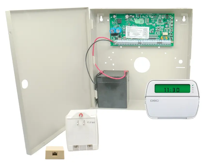
Wiring Diagram
Wiring the 5530M communicators to DSC PC1616 / 1832 / 1864 via key switch zone:
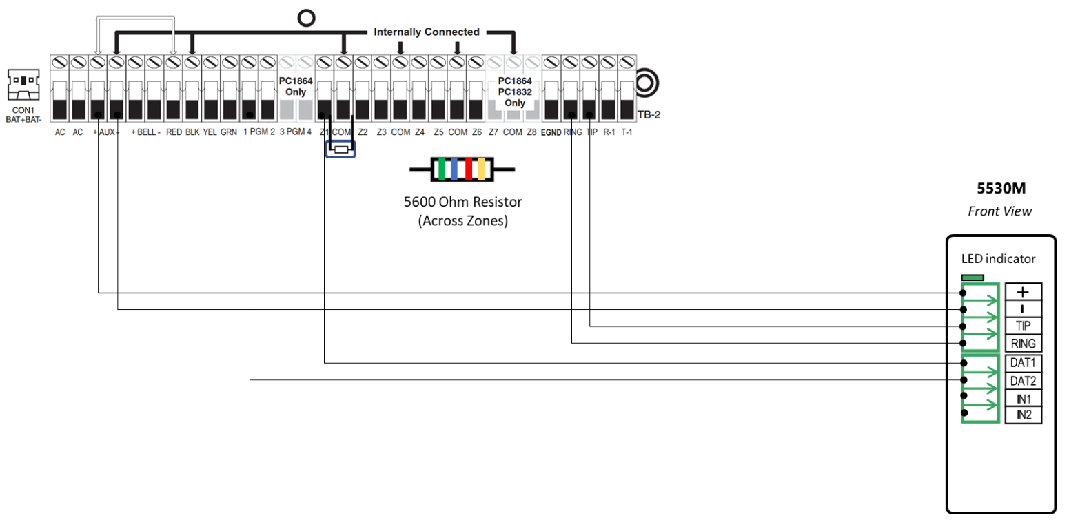
Wiring the 5530M communicators to DSC PC1616 / 1832 / 1864 for events reporting and remote control via keybus:
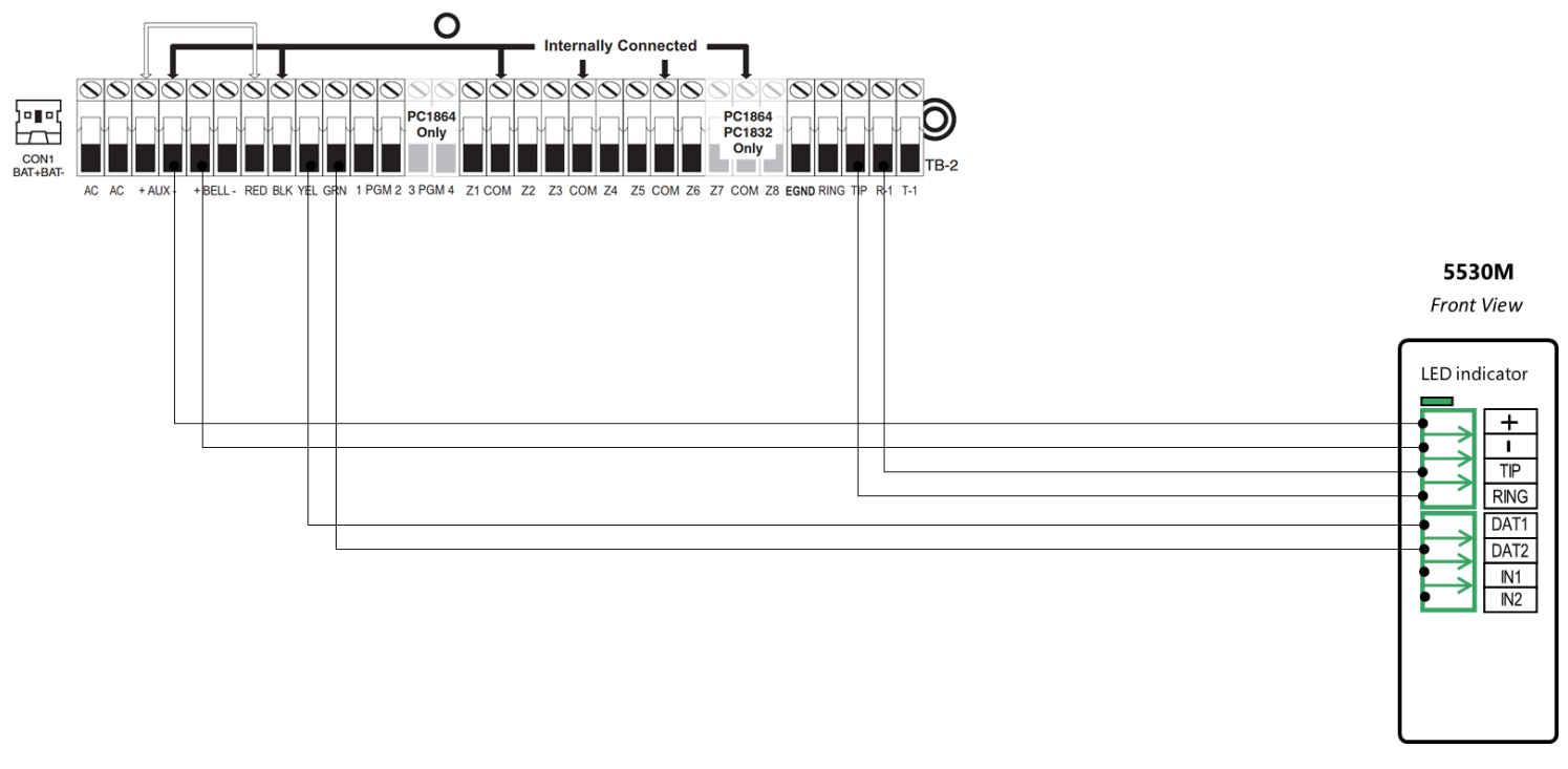
Wiring the 5530M with UDM to DSC PC1616 / 1832 / 1864 for remote upload/download.
Specification
Programming the DSC PC1616 / 1832 / 1864 Alarm Panel via the Keypad
Enable Contact ID reporting:
| LED indication on Keypad | Keypad Entry | Action Description (usually those keypads don’t have display – just LEDs) |
| Armed: steady Red | *85555 | To enter in Programming mode. |
| Ready: steady Green | 301 | To enter menu” First phone number”. |
| Ready: steady Green | 123456* 6*# | Enter actual or non-existing number (any number will do, “123456” is an example) followed by *6* (F in hex). |
| Armed: steady Red | 310 | To enter menu “System account code”. |
| Ready: steady Green | 1234*66 | Enter 4-digit account number to receive the events from (“1234” is an example) and close it with *66 in hex. |
| Armed: steady Red | 311 | To enter menu “Partition 1 account code” |
| Ready: steady Green | 1234 | Enter 4-digit account number to receive the events from (“1234” is an example). |
| Armed: steady Red | 350 | Program Alarm Format. |
| Ready: steady Green | 03# | 03 is for Contact ID. |
| Armed: steady Red | 351 | To program phone 1 call direction. |
| Ready: steady Green | 1# | Toggle 1 to ON for alarms. |
| Armed: steady Red | 367 | Open/Close Communicator Call directions for partition 1 (if you have more partitions, repeat this and the next step for 368,369, 370 for partition 2,3,4). |
| Ready: steady Green | 1# | Toggle 1 to ON to enable Open/Close reports (if 1 on the keypad is lit – then it’s ON). |
| Armed: steady Red | 380 | Enter First Communication Options. |
| Ready: steady Green | 1# | Toggle 1 to ON to enable communications (options 3 and 4 must be OFF). |
| Armed: steady Red | 381 | Enter Second Communicator Options. |
| Ready: steady Green | 7# | Toggle 7 to OFF. The system automatically generates all reporting codes transmitted. To manually program the reporting codes in the menu 381, enable option 7 to ON and then set the desired reporting codes in menus 320 to 348. |
| Ready: steady Green | # | Exit Programming mode. |
Program Key-switch zone and output:
| LED indication on Keypad | Keypad Entry | Action description |
| Armed: steady Red | *85555 | To enter in Programming mode. |
| Ready: steady Green | 202 | To enter Partition zone assignments. |
| Ready: steady Green | 1# | Turn ON (the corresponding LED will be lit) only the zones that you intend to use – the rest must be OFF (LEDs are dim) – in our case LEDs 2-7 will be OFF. |
| Armed: steady Red | 001 | To configure Zone 1. |
| Ready: steady Green | 22# | Enter 22 to program zone Type Key switch. |
| Armed: steady Red | 013 | To program EOL zones. |
| Ready: steady Green | 1# | 1 must be OFF to set the zones to end-of-line wiring configuration. |
| Armed: steady Red | 009 | To program Output 1. |
| Ready: steady Green | 05# | Output will activate/deactivate upon arm/disarm for selected partitions. |
| Ready: steady Green | # | Exit Programming mode. |
Programming the DSC PC1616 / 1832 / 1864 Alarm Panel via the Keypad for remote Upload/Download (UDL)
Program the Panel for Upload/Download (UDL):
| Display | Keypad Entry | Action Description |
| Date / Time | *8 + Inst. Code | Enter programming menu. Default installer code is “5555.” |
| Enter section | 401 | First downloading options toggle menu. |
| Toggle option | 1,3,6# | 1 and 3 should be disabled. 6 should be enabled. |
| Enter section | 403 | DLS downloading access code. Default for Impasse is “905700”. |
| Enter Hex Data | 161600# | Set this field’s value to its default (for DSC1832->183200 and for DSC1864->186400). |
| Enter section | 404 | Panel ID code. Default for Impasse is “905700”. |
| Enter Hex Data | 161600# | Set this field’s value to its default (for DSC1832->183200 and for DSC1864->186400). |
| Enter section | 405 | Double call timer address. |
| Enter Data | 000# | Disable double call. |
| Enter section | 406 | Number of rings address. |
| Enter Data | 001 | Set the panel to answer on the first ring. |
| # | Exit Programming mode. |
Configuring the Keybus Functionality
Power OFF and power ON the communicator, wait for ~20 sec., and enter and exit programming mode on the panel to initiate synchronization with the panel.
OR
Log in the Uplink App and press Sync with Panel and follow the instructions in the App.
NOTE: If panel programming is changed after the initial synchronization you need to:
Go to Uplink App Settings >> Remote Arming/Disarming >> Press Sync and follow the instructions in the App
NOTE: DO NOT operate the keypad during the sync process

Documents / Resources
 |
Uplink PC1616 Alarm Cellular Communicators and Programming the Panel [pdf] User Guide PC1616 Alarm Cellular Communicators and Programming the Panel, PC1616, Alarm Cellular Communicators and Programming the Panel, Communicators and Programming the Panel, Programming the Panel |


