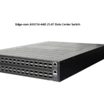
UfiSpace S9110-32X 100G Data Center Switch

Specifications
- Total package contents weight: 29.76lbs (13.5kg)
- Chassis weight without FRU: 16.4lbs (7.44kg)
- Power Supply Unit (PSU) weight:
- DC PSU: 2.2lbs (1.0kg)
- AC PSU: 2.6lbs (1.2kg)
- Fan module weight: 0.41lbs (185g)
- Grounding lug kit weight: 0.037lbs (17g)
- Adjustable mounting rail weight: 0.69lbs (315g)
- USB 3.0 cable weight: 0.04lbs (17.2g)
- AC power cord weight (AC version only): 0.72lbs (325g)
- RJ45 to DB9 female cable weight: 0.23lbs (105g)
- S9110-32X dimensions (W x D x H): 17.32 x 18.9 x 1.72 inches (440 x 480 x 43.8mm)
- PSU dimensions (W x D x H): 1.99 x 10.35 x 1.57 inches (50.5 x 263 x 40.2mm)
- Fan module dimensions (W x D x H): 1.71 x 3.93 x 1.57 inches (43.4 x 100 x 40mm)
Overview
The UfiSpace S9110‐32X is a high‐performance, versatile open networking white box switch that is designed to address the fast-growing segment of the Ethernet switching market and the need to push capacity to the next level. With 32 x 100G QSFP28 ports, the S9110‐32X switch is where computer resources (servers or blade chassis) are centralized and managed in a structured way utilizing high‐efficiency Ethernet connectivity. With advanced capabilities, these switches deliver performance and intelligence to the network edge in a flexible 1RU form factor that helps reduce infrastructure and administrative costs. The S9110‐32X is the epitome of future networking with a powerful 4‐core processor and 32 high‐speed 100G interfaces. It comes with redundant, hot-swappable components for convenience, increased availability, reliability, and lower costs of maintenance. This document describes the hardware installation process for S9110‐32X.
Preparation
Installation Tools
 Phillips #2 Screwdriver
 Crimping tool
 10 AWGwirese with ring terminal for DC power supply
 6‐AWG wire for grounding
 Wire‐stripping tools for stripping 6‐AWG copper wire
- Console cable
- PC with terminal emulation software. Refer to the “Initial System Setup” section for details.
- Baud rate: 115200 bps
- Data bits: 8
- Parity: None
- Stop bits: 1
- Flow control: None
Installation Environment Requirements
- Power Reserve: The S9110‐32X power supply is available with:
- DC Version: 1+1 active‐active ‐36 to ‐75V DC power supply field replaceable unit or;
- AC Version: 1+1 active‐active 100 to 240V AC power supply field replaceable unit.
To ensure the active‐active feed power design functions properly, a field wita h dual power circuit is recommended with a reserve of at least 750 watts on each power circuit.
- Space Clearance: The S9110‐32X width is 17.32 inches (44.0cm) and shipped with rack mount brackets suitable for 19-inch (43.8cm) wide racks. The depth of the S9110‐32X chassis is 18.9 inches (48cm) without the field replaceable units (FRUs) and comes with adjustable mounting rails suitable for rack depths of 22 inches (55.9cm) to 33 inches (83.8cm). The handle for the fan units will extend outwards by 1 inch (2.5cm) and the handle for the power supplies will extend outwards by 1.5 inches (3.8cm). Therefore, to accommodate the fan and power supply handles, a minimum space clearance of 6 inches (15.24cm) is needed at the back of the S9110‐32X. A total minimum reserve depth of 25.9 inches (65.79cm) is required.


- Cooling: The S9110‐32X has two options for airflow direction. There is a back‐to‐front option (Figure 3. Left) and a front‐to‐back option (Figure 3. Right). Make sure the equipment on the same rack has the same airflow direction.
Note: Ensure all installed fans and power supply units (PSUs) have matching airflow directions (indicated by the same handle color) to maintain proper system operation.

Preparation Check List


Package Contents
Accessory List


Component Physical Information

Identifying Your System
S9110‐32X System Overview


DC Version PSU Overview
1+1, hot-swappable power supply unit (PSU) field replaceable unit (FRU). There are two types of DC PSUs. The picture on the left is the DC PSU with back‐to‐front airflow, identified with a blue latch. The picture on the right is the DC PSU for front‐to‐back airflow, identified with a red latch. The DC power supply units are the same size for both back‐to‐front airflow and front‐to‐back airflow. Therefore, only the dimensions for front‐to‐back airflow PSU will be provided in the figure below.
AC Version PSU Overview
1+1, hot-swappable power supply unit (PSU) field replaceable unit (FRU). There are two types of AC PSUs. The picture on the left is the AC PSU with back‐to‐front airflow, identified with a blue latch. The picture on the right is the AC PSU for front‐to‐back airflow, identified with a red latch. The AC power supply units are the same size for both back‐to‐front airflow and front‐to‐back airflow. Therefore, only the dimensions for front‐to‐back airflow PSU will be provided in the figure below.
Fan Overview
 2+1, hot-swappable fan field replaceable unit (FRU). There are two types of fans, shown in the figure below. The top picture is for fans with back‐to‐front airflow, identified with a blue handle. The picture on the bottom is for the fans with front‐to‐back airflow, identified with a red handle.
NOTE: Ensure all installed fans and power supply units (PSUs) have matching airflow directions (indicated by the same handle color) to maintain proper system operation.
Port Overview


Rack Mounting
 Secure the rack mount brackets onto the router. Align the rack mount brackets with the holes provided on the sides of the case and secure the brackets using the 8 M4.0*L6.5mm screws provided with the package.
 Secure the router firmly onto the rack posts. Mark the location on both posts to ensure it is leveled before securing the router firmly onto the rack. (See Figure 13). For a 4-post rack, first, secure the adjustable mounting rail to the back of the router using the M4.0*L6.5mm screws provided in the package. Then secure the adjustable mounting rail to the rack posts. (See Figure 14).
Caution: It is recommended that two trained professionals do installation. One individual should hold the equipment in position on the rack while the other secures it in place.
- The adjustable mounting rail is only used to secure the router to the rack. Please do not perform any service while the adjustable mounting rail is in the extended position.
NOTE: Illustrations are for reference purposes only. Actual equipment and scenarios may differ. Screws for rack posts are not included.
Installing Fan Modules
The fan modules are hot-swappable field replaceable units (FRUs), which can be replaced while the router is operating as long as all the remaining modules are installed and in operation. The fans come pre‐installed and the following steps are instructions on how to install a new fan module.
 Loosen the captive screw located on the fan module.
 Grip the fan’s handle and firmly pull it out of the fan bay.
- Align the new fan module with the fan bay.
- Carefully slide the new fan module into the fan bay and gently push until it is flush with the case.
 Secure the captive screw on the fan module to lock the fan in place.
Installing Power Supply Units
The power supply unit (PSU) is a hot-swappable field replaceable unit (FRU) and can be replaced while the router is operating as long as the remaining (second) PSU is installed and in operation. The PSUs come pre‐installed and the following are instructions on how to install a new PSU. The process for removing and installing the PSUs is the same for all models.
DC
 AC
AC
Shock hazard: For safety, please disconnect all power inputs from the power supply unit before servicing the router.
- Locate the release tab on the PSU. Then press and hold down the release tab to unlock the PSU from the power bay.
- While holding down the release tab, grip the PSU’s handle and firmly pull it out of the power bay.
- DC Version:

- AC Version:

- DC Version:
- Align the new PSU with the power bay, ensuring the PSU’s power connector is in the correct position.
- Carefully slide the new PSU into the power bay and gently push until it is flush with the case.
- An audible click will be heard when the PSU is installed correctly. The PSU will not go all the way if it is in the wrong direction.
- DC Version:

- AC Version:

- DC Version:
NOTE: Illustrations are for reference purposes only. The actual PSU position may differ.
Grounding the Router
It is recommended that equipment changes be done on a grounded rack system. This will reduce or prevent the risk of shock hazards, equipment damage, and potential data corruption. The router can be grounded from the router’s case and the power supply units (PSUs). When grounding the PSUs, ensure that both PSUs are grounded at the same time in case one of them is removed. A grounding lug and M4 screws and washers are provided with the package contents, however, the grounding wire is not included. For convenience, there are two locations on the case in which the grounding lug may be fixed. The following instructions are for grounding the router.
- Before grounding the router, ensure that the rack is properly grounded and in compliance with local regulatory guidelines. Ensure that there is nothing that can obstruct the connection for grounding and remove any paint or materials that may prevent good grounding contact.
- Strip the insulation from a size #6 AWG grounding wire (not provided within the package contents), leaving 0.5” +/‐0.02” (12.7mm +/‐0.5mm) of the exposed grounding wire.
- Insert the exposed grounding wire into the hole of the grounding lug (provided with package contents).
 Using a crimping tool, firmly secure the grounding wire to the grounding lug.
 Locate the designated location for securing the grounding lug, which is located on the side of the router, and remove the protective label.
 Using 2 M4 screws and 2 washers (provided with the package contents), firmly lock the grounding lug to either of the designated grounding locations on the router.
WARNING: This equipment must be grounded. Do not defeat the ground conductor or operate the equipment without correctly grounding the equipment. If there is any uncertainty about the integrity of the equipment’s grounding, don’t hesitate to get in touch with the electrical inspection authority or a certified electrician.
Connecting Power
DC Version
- Ensure there is enough power to supply the system: The maximum system power consumption is 530.7 watts. It is recommended to ensure that enough power is reserved from the power distribution system before installation. Also, please ensure that both PSUs have been properly installed before powering up the equipment, as the S9110‐32X is designed to support 1 + 1 power redundancy.
 Attach the power cable: Locate the DC power screw‐type terminal block on the DC PSU. Attach the UL 1015, 10 AWG DC power cable (not provided within the package contents) to the DC inlet connector on the PSU.
Dangerous voltage:- Must be powered off before removing!
- Verify that all electrical connections are grounded before powering on
- The DC power source must be reliably grounded
 Tighten the screws to the specified torque: Tighten the screws to a torque value of 7.0+/‐0.5kgf.cm. If the torque is not enough, the lug will not be secure and may cause malfunctions. The terminal block or lug may be damaged if the torque is too much.
- Feed DC power into the system: The PSU will immediately output 12V and 5VSB to the system when a ‐40V to ‐75V DC power source is applied. The PSU has a built-in 30 amperes, fast-acting fuse based on the PSU maximum capacity, which will act as second-tier system protection in case the power distribution unit’s fuse is not functioning.
- Verify that the power supply is operating: If connected correctly, when turned on, the LED on the PSU will light up with a Green color designating normal operation.
AC Version
- Ensure there is enough power to supply the system: The maximum system power consumption is 530.7 watts with an input voltage of 100‐240V AC. It is recommended to ensure that enough power is reserved from the power distribution system before installation. Also, please ensure that both PSUs have been properly installed before powering up the equipment, as the S9110‐32X is designed to support 1 + 1 power redundancy.
- Attach the power cable: Plug the power cord into the AC PSU and secure it tightly.
 Verify that the power supply is operating: If connected correctly, when turned on, the LED on the PSU will light up with a Green color designating normal operation.
Verifying System Operation
Front Panel LED
 Verify basic operations by checking the system LEDs located on the front panel. When operating normally, the SYS, FAN, and PSU LEDs should all display green.

PSU FRU LED
Additional information about the PSU status can be obtained from the LEDs located on the PSU itself
Fan FRU LED

Management Port LED

Initial System Setup
Establishing a first‐time serial connection
To assign an IP address, you must have access to the command line interface (CLI). The CLI is a text-based interface that can be accessed through a direct serial connection to the device. Access the CLI by connecting to the console port. After you assign an IP address, you can access the system through Telnet or SSH by Putty, TeraTerm, or HyperTerminal. Perform the following steps to access the device through a serial connection:
- Connect the console cable:

- The console can be connected using the RJ45 port labeled IOIO.
- To connect to the console, plug an RJ45 serial cable into the console port and connect the other end to the computer. Cable types may vary depending on the model.
- Check for serial control availability:
Disable any serial communication programs running on the computer such as synchronization
programs to prevent interference. - Launch a terminal emulator: Open a terminal emulator application such as HyperTerminal (Windows PC), Putty, or TeraTerm and configure the application. The following settings are for a Windows environment (other operating systems will vary):
- Baud rate: 115200 bps
- Data bits: 8
- Parity: None
- Stop bits: 1
- Flow control: None
- Login to the device: After the connection is established, a prompt for the username and password displays. Enter the username and password to access the CLI. The username and password should be provided by the Network Operating System (NOS) vendor.
Cable Connections
Connecting the USB Cable
 Connect the USB 3.0 A Type plug (male connector) to the USB port (female connector) located on the front panel of the router.
Connecting the OOB Management Cables
 Connect the OOB management cable by locating the RJ45 OOB port marked a
 ![]() symbol.
symbol.
Connecting the Management Cables
 There is a 1G SFP port available to connect to management. This port is marked with an orange “MGMT”.
Connecting the Transceivers
Read the following guidelines before connecting the transceiver:
- Before installing the router, take into consideration rack space requirements for cable management and plan accordingly.
- It is recommended to use hook‐and‐loop style straps to secure and organize the cables.
- For easier management, label each fiber‐optic cable and record its respective connection.
- Maintain a clear line of sight to the port LEDs by routing the cables away from the LEDs.
NOTE: To prevent over-tightening and damaging the optic fibers, it is not recommended to use tie wraps with optical cables.
CAUTION: Before connecting anything (cables, transceivers, etc.) to the router, please ensure to discharge any static electricity that may have built up during handling. It is also recommended the cabling be done by a professional who is grounded, such as by wearing an ESD wrist strap.
Please follow the steps below for connecting a transceiver.
- Remove the new transceiver from its protective packaging.
- Remove the protective plug from the transceiver port.
- Place the bail (wire handle) in the unlocked position and align the transceiver with the port.
- Slide the transceiver into the port and use gentle pressure to secure it in place. An audible click can be heard when the transceiver is secured in the port.
Cautions and Regulatory Compliance Statements
Caution! Shock hazard: TO DISCONNECT POWER, REMOVE ALL POWER CORDS FROM UNIT.
Electrical Hazard: Only qualified personnel should perform installation procedures.
Warning: Network Switch power supplies do not have switches for turning the unit on and off. Before servicing, disconnect all power cords to remove power from the device. Make sure that these connections are easily accessible.
Caution: Before mounting the device, ensure that the rack can support it without compromising stability. Otherwise, personal injury and/or equipment damage may result.
Caution: Use of controls or adjustments or performance of procedures other than those specified herein may result in hazardous radiation exposure.
Caution: Only Laser Class 1 optical transceivers shall be used.
Warning: Do not use optical instruments to view the laser output. The use of optical instruments to view laser output increases eye hazard. Use only UL/CSA, IEC/EN60825‐1/‐2 recognized pluggable modules.
Warning: The equipment should only be used within a restricted access area. The equipment should only be operated by skilled or instructed persons. The equipment and its modules should only be repaired, maintained,d or replaced by skilled personnel. Instructed person is a term applied to persons who have been instructed and trained by a skilled person, or who are supervised by a skilled person.
Class A ITE Notice
WARNING: This equipment is compliant with Class A of CISPR 32. In a residential environment,t this equipment may cause radio interference.
VCCI Notice
This is Class A equipment. Operation of this equipment in a residential environment could cause radio interference. In such a case, the user may be required to take corrective actions.
WEBSITE: http://www.ufispace.com/
FAQs
Q: What are the power voltage and electric current requirements for the S9110-32X?
A: The DC version requires -36 to -75VDC, with a maximum of 28A x2, while the AC version needs 100 to 240VAC with a maximum of 10A x2 or 190 to 310VDC with a maximum of 5A x2.
Q: What are the installation spacing requirements for the S9110-32X?
A: The S9110-32X spacing requires a height of 1RU (1.72 inches), a width of 19 inches, and a depth of 18.9 inches.
Q: What tools are required for the installation of the S9110-32X?
A: You will need a #2 Phillips Screwdriver, a wire stripper for 6-AWG wire, and a crimping tool, along with accessories like a PC with terminal emulation software, console cable, and specific wires for power and grounding.
Documents / Resources
 |
UfiSpace S9110-32X 100G Data Center Switch [pdf] Installation Guide S9110-32X, S9110-32X 100G Data Center Switch, S9110-32X, 100G Data Center Switch, Data Center Switch, Center Switch, Switch |