![]() Compact Linear Systems
Compact Linear Systems
Installation Manual
Edition 2022-09

Compact Linear Systems
www.thomsonlinear.com
Version history
| Edition | Reason for revision |
| 2022-09 | First edition |
Warranty
The Thomson compact linear system is warranted to be free from defects in materials and workmanship for a period of twelve (12) months from date of delivery. The application of this product is the responsibility of the buyer and Thomson makes no representation or warranty as to the suitability of the product for any particular use or purpose. For a copy of the entire warranty for this product that is contained in our standard terms and conditions of sale, please go to
http://www.thomsonlinear.com/website/com/eng/support/terms_and_conditions.php.
Disclaimer
Technical changes to improve the performance of the equipment may be made without prior notice!
All rights reserved. No part of this work may be reproduced in any form (by printing, photocopying, microfilm or any other method) or processed, copied or distributed by electronic means without the written permission of Thomson.
General
1.1 About this manual
This manual contains mechanical and electrical installation instructions for the Thomson compact linear systems. It also contains, among other things:
- technical data
- installation data
- type designation key.
It is important to carefully read this manual before installing the linear system and to have the correct qualifications needed to perform the installation.
1.2 Target group
This manual addresses qualified mechanical and electrical personnel.
1.3 Symbols used
![]() This symbol is shown to highlight a general warning, general instruction or as a warning for a mechanical hazard.
This symbol is shown to highlight a general warning, general instruction or as a warning for a mechanical hazard.
1.4 Transport and storage
The linear system may only be transported and stored in the original packaging supplied by Thomson.
The temperature during transportation and storage must be between -40 to +85° C (-40 to +185° F).
Avoid shocks to the package. If the package is damaged, check the linear system for visible damage and notify the carrier, and if appropriate also Thomson.
1.5 Packaging
The packaging consists of a cardboard box. The box contains the linear system and this manual. For large quantity orders, bulk packaging may be used in which case the packaging and the content will vary depending on the order agreement.
1.6 Disposal
Where required by law, used packaging and linear systems are taken back by Thomson for professional disposal if the transportation cost is paid by the sender. Please contact Thomson for shipping information.
1.7 Support
If technical support or information is needed for this product, please contact the nearest Thomson Service Center. See the back of this manual. You can also visit www.thomsonlinear.com for information on this product and how to contact us.
Safety and Standards
Safety
2.1 Safety notes
 Only properly qualified personnel are permitted to perform mechanical and electrical installation of this product. Properly qualified personnel are familiar with mechanical or electrical installation work and have the appropriate qualifications for their job.
- Read this manual and any other available documentation before working on the equipment that the actuator is or shall be a part of.
- Conform strictly to the information contained in this manual and on the product label.
Never exceed the performance limits stated herein. - Never work on the linear system or its installation with the power on.
- Never unplug any cables or connectors during operation or with power on.
- Immediately stop using the linear system if it seems faulty or damaged in any way and notify an appropriate person so that corrective actions can be taken.
- Grease may be present on some of the linear system screw and guide surfaces. Contact is non-hazardous. Film should not be removed.
Standards
3.1 EC Declaration of incorporation of partly completed machinery
Declaration of Incorporation of Partly Completed Machinery
(Annex II 1 B of Machinery Directive 2006/42/EC)
Manufacturer:
Thomson Industries Inc.
1500 N Mittel
Wood Dale, II 60191
United States
Description and Identification of the Partly Completed Machinery:
Designation: Compact Linear systems
Series: CLSH, CLSV, CLSR
Sizes: 8, 11, 14, 17, 23
The following essential requirements of Machinery Directive 2006/42/EC have been applied and fulfilled:
Annex I, sections 1.1.2, 1.1.3. 1.1.5, 1.3.2,1.3.4, 1.6.4, 1.7.1, 1.7.3, 1.7.4, 2.2.2.2, 4.1.3
The relevant technical documentation has been complied in accordance with Annex VII, part B of Machinery Directive 2006/42/EC. Upon reasonable request, Thomson will supply the documentation in an electronic format to the responsible governing authorities within a reasonable timeframe.
The party authorized to compile the technical documentation is:
Julian Anton & Ivan Lopez (Product Design Engineers)
The partly completed machinery must not be put into service until the final machinery of which it is to be incorporated in has been declared to be in conformance of the Machinery Directive.
James Marek (VP of Engineering)
![]()
Wood Dale, 2022-09-06 (Location, date)
Installation
4.1 Product label
The product label can be found on the side of the motor case. It will tell you the model of the linear system and the manufactured date. Please review the product label to determine linear system type before starting any installation or service of the linear system. If you need any assistance from Thomson, please provide the part number and the manufacturing date of the linear system(s) in question.![]() 4.2 Terminology
4.2 Terminology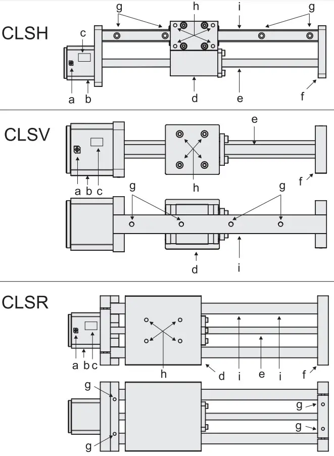 a. lead wires
b. stepper motor
c. product label
d. carriage with nut assembly
e. lead screw
f. end support
g. mounting holes
h. payload mounting holes
i. guide rail
4.3 Operation environment
- Operation temperature range is -4 to +122° Fahrenheit (-20 to 50° Celsius).
- Protection degree against ingress of water and particles is IP40.
- Max non-condensing humidity is 85%.
4.4 Mechanical installation
4.4.1 General installation safety notes
- Never work on the linear system with the power switched on.
- Keep hands clear while the unit is energized.
- Pinch points are present between the end support/motor mount and carriage.
- Failure modes of the linear system should be considered to ensure it does not create harm.
4.4.2 Basic installation considerations
- Only mount the linear system using the designated mounting holes on the guide rail (CLSH and CLSV) or mounting blocks (CLSR). Check the part number on the product label (section 4.1) and cross reference with the ordering key (section 6.2) to determine which mounting style is used in your assembly.
- Make sure that the linear system mounting position allows access to the lead wires so that it can be properly connected and powered on.
- Make sure that there is enough clearance surrounding the carriage to allow it to freely move.
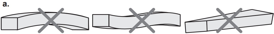
4.4.3 Mounting surface
- The mounting surface should be flat and free from any dust, dirt or debris.
- The surface must be straight so that it does not bend, twist or skew the unit (a).
 4.4.4 Mounting of CLSH and CLSV units
- The mounting holes are situated in the guide rail. Their exact position and dimensions depend on the size of the profile rail and can be found in the table below.
- The first mounting hole (Y) on the motor side has a positional tolerance of ± 1.0 mm from the end of the guide rail.
- The positional tolerance between the rest of the mounting holes (X) are 0.5 mm.
- When bolting the unit to the surface, first insert screws in the mounting holes and tighten lightly.
Then starting from the center of the rail moving outwards, tighten each screw to the recommended tightening torque listed in the table in section 4.4.6.
| CLSH/CLSV mounting holes | |||
| Style | Size | X [mm] | Y [mm] |
| CLSH | 15F | 60 | 20 |
| CLSV | 9A | 20 | 7.5 |
| CLSV | 12A | 25 | 10 |
| CLSV | 15A | 40 | 15 |
| CLSV | 15F | 60 | 20 |
 4.4.5 Mounting of CLSR units
- The mounting holes are situated in the end supports (Z). Their exact position and dimensions depend on the size of the round rail and motor size and can be found in the table below.
- When bolting the unit to the surface, first insert screws in the mounting holes and tighten lightly.
Then tighten each screw to the recommended tightening torque listed in the table in section 4.4.6.
| Motor Size | Bearings | P [mm] | R [mm] | X [mm] | Y [mm] |
| NEMA 23 | R08 | 29.0 | 60.0 | 17 | 6.35 |
| NEMA23 | R06 | 20.5 | 60.0 | 17 | 6.35 |
| NEMA 17 | R08 | 29.0 | 64.75 | 17 | 6.35 |
| NEMA 17 | R06 | 20.5 | 60.5 | 17 | 6.35 |
 4.4.6 Recommended bolt tightening torque table
| Recommended bolt tightening torque [Nm] | |||||||||
| Class | Size | ||||||||
| M2.5 | M4 | M5 | M6 | M8 | M10 | M12 | M14 | M16 | |
| 9. | 0.7 | 2.8 | 5.7 | 9.5 | 23 | 46 | 80 | 129 | 198 |
| 13. | 1.2 | 4.6 | 9.58 | 16 | 39 | 77 | 135 | 215 | 330 |
4.5 Electrical installation
4.5.1 General notes
- Make sure the leads/cables leading to the motor can handle the maximum motor current.
- Do not exceed the peak current of the motor. Peak current is 1.41 × RMS current.
- An emergency stop is recommended to reduce the chance of a crushing hazard.
- Never work on the linear system or the wiring with the power switched on.
4.5.2 Electrical connections
The linear system motor is always supplied with flying lead wires that are attached to the stepper motor.
These lead wires are used to connect to the stepper motor and drive the carriage. Depending on the configuration, motors have various wire gauge sizes. The standard gauges are outlined in the table below.
| Configuration | Wire gauge |
| NEMA14Axx | 26 AWG |
| NEMA17Axx | 26 AWG |
| NEMA17Bxx | 26 AWG |
| NEMA23Axx | 22 AWG |
| NEMA23Bxx | 22 AWG |
4.5.3 Wiring diagram
| Motor wiring | |
| Lead color | Motor phase |
| Blue | A – |
| Red | A + |
| Black | B – |
| Green | B+ |
4.6 Stepper motor control
4.6.1 Driving the stepper motor
There are many possible ways to drive a stepper motor. The most common way is to use a constant current or “chopper” drive. A chopper drive works by limiting the current into the stepper motor and “chopping” the voltage, allowing for maximum torque output from the motor. When using this type of drive, it is important to input the appropriate amount of current to maximize torque output and prevent damage to the motor. Recommended drive currents are determined using the following equations, where RMS current is the motor rated current found in the brochure:
When full stepping:
Drive current = RMS current
When micro stepping:
Drive current = peak current = 1.41 × RMS current
| Drive current of standard configurations | |||
| Configuration |
Rated RMS motor current [A] |
Drive current @ full stepping [A] |
Drive current @ micro stepping [A] |
| CLSx14A08 |
0.88 |
0.88 |
1.24 |
| CLSx14A13 |
1.35 |
1.35 |
1.90 |
| CLSx17A10 | 1.00 | 1.00 |
1.41 |
| CLSx17A15 |
1.50 |
1.50 |
2.12 |
| CLSx17B10 |
1.00 |
1.00 |
1.41 |
| CLSx17B15 |
1.50 |
1.50 |
2.12 |
| CLSx23A15 |
1.55 |
1.55 |
2.19 |
| CLSx23A30 |
3.00 |
3.00 |
4.23 |
| CLSx23B19 |
1.90 |
1.90 |
2.68 |
| CLSx23B39 |
3.90 |
3.90 |
5.50 |
4.6.2 Power supply voltage
When using a current limiting “chopper” drive, power supply voltage selection is completely dependent on your requirements and/or voltage availability. The voltage input into the motor impacts the performance of the stepper in regards to speed. For example, a stepper motor will usually perform better at higher speeds when a higher voltage is utilized. Typical voltage ranges are 12, 24 and 40 Vdc. All performance diagrams in the Compact Linear Systems brochure are generated with either 24 or 40 Vdc power supplies.
Technical specifications
5.1 Technical data
| Lead Screw | ||||
| Material | 300 Series Stainless Steel | |||
| Standard Coating’ | None | |||
| Standard Lead Accuracy | [in./ft. (pm/300 mm)] | 0.010 (250) | ||
| Precision Lead Accuracy | [in./ft. (pm/300 mm)] | 0.003 (75) | ||
| Straightness | [in./ft. (pm/300 mm)] | 0.005 (125) | ||
| Lead Nut | ||||
| Standard Material | Internally lubricated acetal | |||
| High Performance Material | Internally lubricated engineered thermoplastic | |||
| Nut Efficiency2 | [%) | Up to 85 | ||
| Typical Linear Travel Life | [in. (km)] | 10 x 106(250) | ||
| Positional Repeatability with Standard Nut3 | [in. (mm)] | 0.005 to 0.010 (0.127 to 0.254) | ||
| Positional Repeatability with Anti-Backlash Nut4 | [in. (mm)] | <0.002 (0.051) | ||
| Motor | ||||
| Frame Size | NEMA 14 | NEMA 17 | NEMA 23 | |
| Step Size | [c.] | 1.8 | 1.8 | 1.8 |
| Concentricity of Mounting Pilot to Shaft | [in. (mm)] | 0.003 (0.08) TIR | ||
| Perpendicularity of Shaft to Mounting Face | [n. (mm)] | 0.003 (0.08) TIR | ||
| Max. Case Temperature | [°F (°C)] | 176 (80) | ||
| Storage Temperature | [°F (°C)] | -4 to 122 (-20 to 50) | ||
| Ambient Temperature | [°F (°C)] | -4 to 122 (-20 to 50) | ||
| Max. Humidity (non-condensing) | [%] | 85 | ||
| Magnet Wire Insulation | Class B 130 °C (266 °F) | |||
| Insulation Resistance | 100 Mohm @ 500 VDC | |||
| Dielectric Strength | 500 VAC for 1 minute | |||
| Assembly | ||||
| Max. Backlash with Standard Nuts | [in. (mm)] | 0.010 (0.25) | ||
| Operating Temperature | [°F (°C)] | 15 to 125 (-10 to 50) | ||
- Contact Thomson for optional lead screw coatings.
- Depending on lead, nut material and lubrication.
- Depends on nut, load and orientation.
- For best positional repeatability, load should be kept well below design system.
- Nut fit can be adjusted depending on backlash requirements.
5.2 Ordering Key
| Ordering Key | |||||||||||||||||
|
1 |
2 | 3 | 4 | 5 | 6 | 7 | 8 | 9 | 10 | 11 | 12 | 13 | 14 | 15 | 16 | 17 | 18 |
| CLSV | 14 | A | 13 | – 31 | 0500 | S | 06000 | N – | X | MT | 2 | P | 09 | A | 0 | XX |
|
| 1. Series CLSV = Vertical Architecture CLSH = Horizontal ArchitectureCLSR = RoundRail Architecture 2. Motor size 14 = NEMA 14, 17 = NEMA 17, 23 = NEMA 23 3. Motor stack A = Single B = Double 4. Motor current rating 08 = 0.8 A 10-= 1.0 A 13 = 1.3 A 15 = 1.5 A 19 = 1.9 A 30 = 3.0 A 39 = 3.9 A 5. Screw diameter 31 = 0.3125 in 37 = 0.3750 in M08 = 8.0 mm M10 = 10.0 mm 6. Linear travel/rev 0050 = 0.050 in 0063 = 0.063 in 0079 = 0.079 in 0083 = 0.083 in 0100 = 0.100 in 0125 = 0.125 in 0167 = 0.167 in 0200 = 0.200 in 0250 = 0.250 in 0300 = 0.300 in 0375 = 0.375 in 0500 = 0.500 in 0750 = 0.750 in 1000 = 1.000 in 1200 = 1.200 in 020 = 2.0 mm 030 = 3.0 mm 040 = 0.4 mm 050 = 5.0 mm 060 = 0.6 mm 080 = 0.8 mm 100 = 10.0 mm 120 = 12.0 mm 200 = 20.0 mm |
7. Accuracy grade S = Standard 0.010 in/ft (250 µm/300 mm) P = Precision 0.003 in/ft (125 µm/300 mm) 8. Stroke length 06000 = 6 in (when inch screw diameters) 15000 = 15 mm (when metric screw diameters) 9. Lead screw coating N = None T = PTFE 10. Motor/Rail Orientation X = For CLSV and CLSR L = Left (CLSH only), see image below R = Right (CLSH only), see image below 11. Nut MT = Flange Mount (MTS Series) XF = Triangular Flange, Anti-backlash (XC Series) 12. Nut size 2 = 0.3125 in and 8 mm screws for MT nut 3 = 0.3125 in and 8 mm screws for XF nut, 0.375 in and 10 mm screws for MT and XF nuts  |
13. Linear Bearing Type P = Profile Rail R = Roundrail 14. Linear Bearing Sizes 09 = Profile Rail, Size 9 12 = Profile Rail, Size 12 15 = Profile Rail, Size 15 06 = Round Rail, 3/8” 08 = Round Rail, 1/2” 15. Bearing Designation A = Standard S = Super smart C = Corrosion resistant D = Super smart + corrosion resistant F = 400 Series Profile Rail 16. Limit Switches 0 = No limit switches 17. Encoder XX = No Encoder 18. Custom designation (blank) = Standard configuration 001-999 = Custom configuration |
| EUROPE United Kingdom Thomson Office 9, The Barns Caddsdown Business Park Bideford, Devon, EX39 3BT Phone: +44 1271 334 500 E-mail: sales.europe@thomsonlinear.com |
ASIA Asia Pacific Thomson E-mail: sales.apac@thomsonlinear.com |
| Germany Thomson Nürtinger Straße 70 72649 Wolfschlugen Phone: +49 7022 504 403 Fax: +49 7022 504 405 E-mail: sales.europe@thomsonlinear.com |
China Thomson Rm 805, Scitech Tower 22 Jianguomen Wai Street Beijing 100004 Phone: +86 400 606 1805 Fax: +86 10 6515 0263 E-mail: sales.china@thomsonlinear.com |
| France Thomson Phone: +33 243 50 03 30 E-mail: sales.europe@thomsonlinear.com Italy Thomson Via per Cinisello 95/97 20834 Nova Milanese (MB) Phone: +39 0362 366406 Fax: +39 0362 276790 E-mail: sales.italy@thomsonlinear.com |
India Kollmorgen – Div. of Altra Industrial Motion India Private Limited Unit no. 304, Pride Gateway, Opp. D-Mart, Baner Road, Pune, 411045 Maharashtra Phone: +91 20 67349500 E-mail: sales.india@kollmorgen.com |
| Sweden Thomson Estridsväg 10 29109 Kristianstad Phone: +46 44 590 2400 Fax: +46 44 590 2585 E-mail: sales.europe@thomsonlinear.com |
South Korea Thomson 3033 ASEM Tower (Samsung-dong) 517 Yeongdong-daero Gangnam-gu, Seoul, South Korea (06164) Phone: + 82 2 6001 3223 & 3244 E-mail: sales.korea@thomsonlinear.com |
| USA, CANADA and MEXICO Thomson 203A West Rock Road Radford, VA 24141, USA Phone: 1-540-633-3549 Fax: 1-540-633-0294 E-mail: thomson@thomsonlinear.com Literature: literature.thomsonlinear.com |
SOUTH AMERICA Brazil Thomson Av. João Paulo Ablas, 2970 Jardim da Glória – Cotia SP – CEP: 06711-250 Phone: +55 11 4615 6300 E-mail: sales.brasil@thomsonlinear.com |
www.thomsonlinear.com
Compact_Linear_Systems_MNUK-0019-01 | 20220921TJ
Specifications are subject to change without notice. It is the responsibility of the product user to determine the suitability of this product for a specific application.
All trademarks property of their respective owners. ©2022 Thomson Industries, Inc.
![]()
Documents / Resources
 |
THOMSON Compact Linear Systems [pdf] Instruction Manual Compact Linear Systems, Compact, Linear Systems, Systems |
 |
THOMSON Compact Linear Systems [pdf] Instructions Compact Linear Systems |
 |
Thomson Compact Linear Systems [pdf] Instruction Manual Compact Linear Systems, Linear Systems, Systems |


