![]() Terminator™ ZP-XP
Terminator™ ZP-XP
Power Connection Kit
INSTALLATION PROCEDURES
For Power Connection, In-Line Splice Connection, T-Splice Connection or End Termination Applications
Terminator™ ZP-XP
The following installation procedures are suggested guidelines for the installation of the Terminator ZP-XP Kit. For translations other than English and local language translation provided here, please contact Thermon. The English language installation procedure shall govern.
Kit Contents

| Item | Quantity | Description |
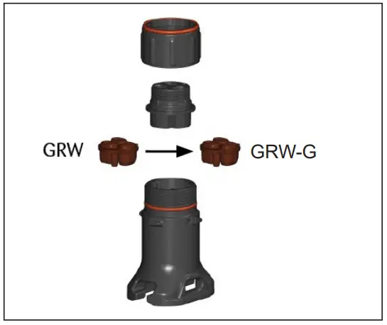
| 1 | 1 | Expediter Assembly Support Cap with 0-Ring Threaded Grommet Compressor Grommet Support Base with 0-Ring |
| 2 | 1 | Junction Box Lid |
| 3 | 1 | Junction Box Base with 0-Ring and M25 Dust Cap |
| 4 | 1 | Nut |
| 5 | 1 | Banding |
| 6 | 1 | Banding Guide |
| 7 | 1 | Terminal Blocks with DIN Rail (Refer to terminal specifications for maximum allowable wire size) |
| 8 | 1 | Junction Box Cord |
| 9 | 1 | Blind Plug |
Order Separately
PETK Power and End Termination Kits (per cable)
| PETK-1 | for RSX, VSX-HT, BSX |
| PETK-2 | for KSX, HTSX, USX |
| PETK-3 | for HPT, FP |
Specific Conditions of Use
Avoid electrostatic charge. Clean only with damp cloth.
Dimensions

Warnings
- Due to the risk of electrical shock, arcing and fire caused by product damage or improper usage, installation or maintenance, a ground-fault protection device is required.
- Installation must comply with Thermon requirements (including form PN 50207U for Ex systems) and be installed in accordance with the regulations as per the norm EN IEC 60079-14 for hazardous areas (where applicable), or any other applicable national and local codes.
- Component approvals and performance ratings are based on the use of Thermon specified parts only.
- De-energize all power sources before opening enclosure.
- Avoid electrostatic charge. Clean only with a damp cloth.
- Keep ends of heating cable and kit components dry before and during installation.
- Minimum bending radius of heating cable is 32 mm (except HPT is 57 mm and FP is 19 mm).
- Individuals installing these products are responsible for complying with all applicable safety and health guidelines. Proper Personal Protective Equipment (PPE) should be utilized during installation. Contact Thermon if you have any additional questions.
Tools Required

Certifications/Approvals
IP66 -60°C ≤ Ta ≤ +55°C
Ordinary & Hazardous Locations
![]() MG 10.0022X Ex eb IIC T6…T4 Gb
MG 10.0022X Ex eb IIC T6…T4 Gb
Ex tb IIIC T85°C…T135°C Db
![]() II 2 GD Ex eb IIC T6…T4 Gb, Ex tb IIIC T85°C…T135°C Db
II 2 GD Ex eb IIC T6…T4 Gb, Ex tb IIIC T85°C…T135°C Db
FM 10ATEX0058X
Thermon has additional hazardous area approvals including:
- GGTN
- Kazakhstan
INSTALLATION PROCEDURES
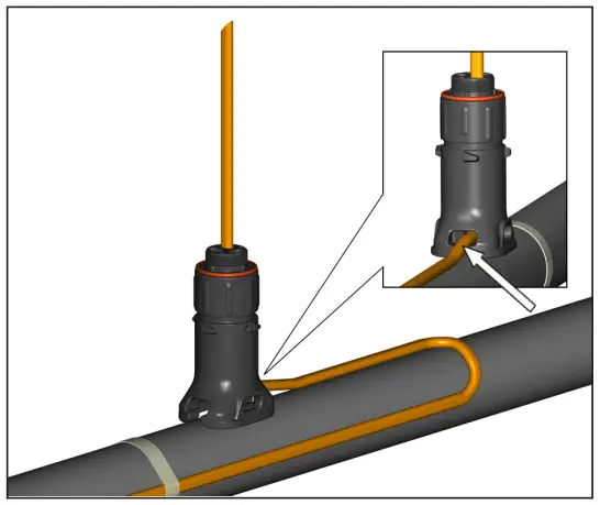
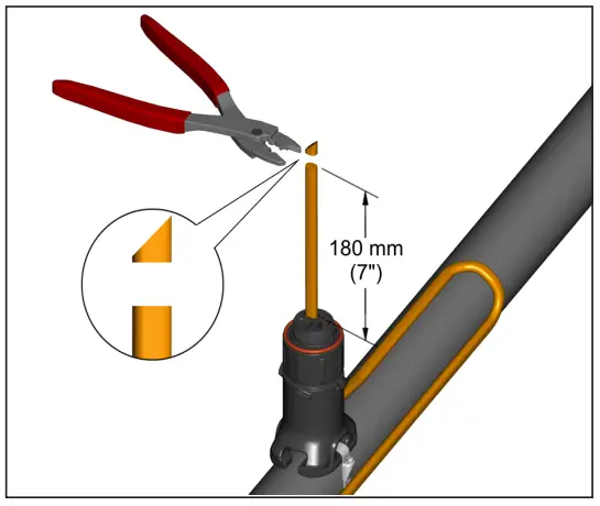
- Locate bus connection (HPT and FP only) and cable as shown. Cut end of cable at angle to aid in piercing grommet. Leave additional cable for expansion loop. See page 5 for multiple cable installation tips.

- For HPT and FP cable, exchange grommet in Terminator with GRW-G provided in PETK-3.
- Insert cable into expediter. If mounted on bottom or side of pipe, punch out weep hole.

- Slide expediter toward pipe and route cable through support base entry.
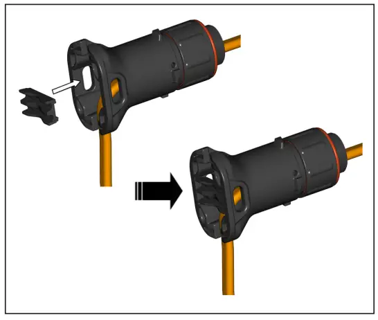
- Insert banding guide into expediter and snap into place.
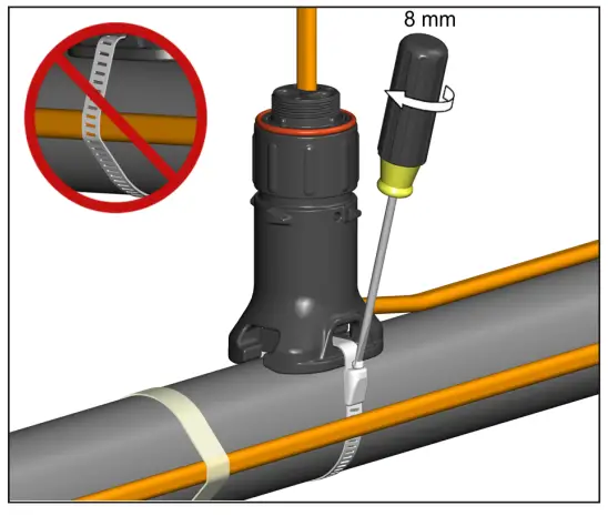
- Mount expediter to pipe using pipe band. Do not band over cable.
- Cut off end of cable.
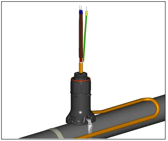
- Terminate cable with appropriate PETK termination kit. Refer to PETK installation instructions.
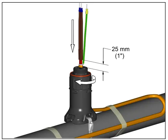
- Push excess cable back through expediter. Tighten cap securely. Tape cable expansion loop to pipe.
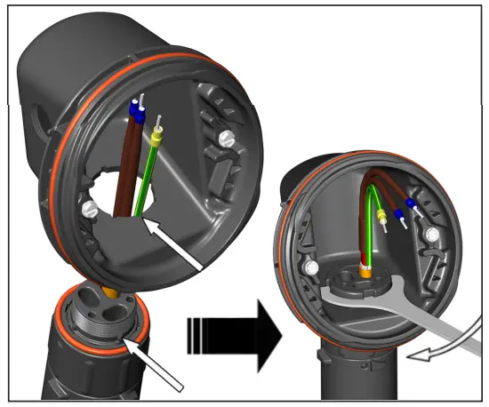
- Mount junction box base on expediter. Make sure to align slots to properly orient junction box base. Tighten nut with Terminator-LN-Tool. If mounting horizontally, threaded gland holes must face downward.
- Remove M25 dust cap. Install M25 power gland (order separately) and M25 blind plug. For in-line splice, T-splice, or end termination, install additional M25 blind lug (order M25-B-EXE separately) instead of M25 power gland.

- Install power cable (if necessary).
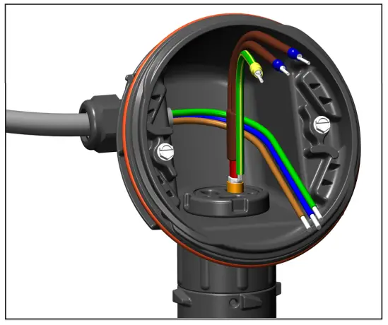
- Install terminal block and complete system wiring. Terminal set screws shall be tightened to a torque value of 1.4 Nm (12.4 lb-in). See below for wiring details.

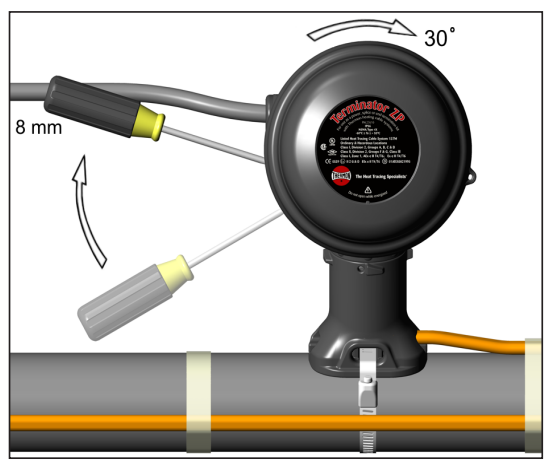
- Install junction box lid and twist hand tight. Insert screwdriver into ratchet slots located on side of junction box base.

- Use screwdriver to ratchet on junction box lid. Lid will rotate 30 degrees.
- Lid latch mechanism fully engaged. To remove lid, repeat steps 14 and 15 but in the opposite direction.

Two Cable Layout Tips
Locate bus connection (HPT and FP only) and cable as shown. Cut end of cable at angle to aid in piercing grommet. Leave additional cable for expansion loop  Insert two cables into expediter. Note: For HPT and FP cable, exchange grommet in Terminator with GRW-G provided in PETK-3.
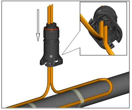 For HPT and FP cable, exchange grommet in Terminator with GRW-G provided in PETK-3.
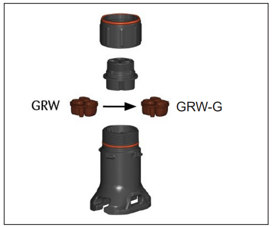 Three Cable Layout Tips
Locate bus connection (HPT and FP only) and cable as shown. Cut end of cable at angle to aid in piercing grommet. Leave additional cable for expansion loop. Insert three cables into expediter. Note: For HPT and FP cable, exchange grommet in Terminator with GRW-G provided in PETK-3.
 Mount expediter with three cables. Do not band over cable.
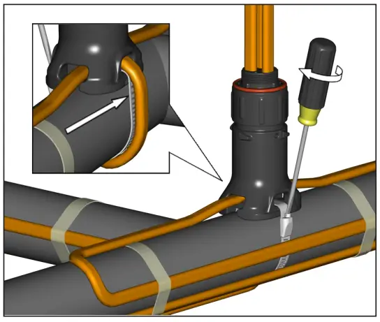 Wiring Details
Power Connection (1 to 3 Heating Cables) In-Line Splice and T-Splice
 End Termination (1 to 2 Heating Cables) Remove jumpers for 2 cable terminations.
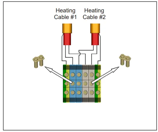 Form PN50845U-1221
European Headquarters: Boezemweg 25 • PO Box 205 • 2640 AE Pijnacker • The Netherlands • Phone: +31 (0) 15-36 15 370
Corporate Headquarters: 100 Thermon Dr • PO Box 609 San Marcos, TX 78667-0609 • Phone: 512-396-5801 • 1-800-820-4328
![]() For the Thermon office nearest you visit us at
For the Thermon office nearest you visit us at
www.thermon.com
© Thermon, Inc.
Printed in U.S.A.
Information subject to change.
Documents / Resources
 |
THERMON Terminator ZP-XP Power Connection Kit [pdf] Installation Guide Terminator ZP-XP Power Connection Kit, Terminator ZP-XP, Power Connection Kit, Connection Kit |