ROGA Instruments SLMOD Dasylab Add On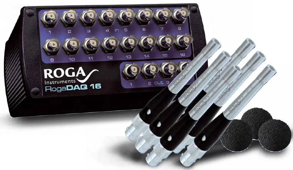 SPM Modules
Specifications
- Module versions: 5.1
- Manufacturer: ROGA Instruments
- Address: Im Hasenacker 56, D-56412 Nentershausen
- Phone: +49 (0) 6485-8815803
- Email: info@roga-instruments.com
Product Information
The ROGA Instruments SLM and SPM Module Manual provides an easy way to determine sound power levels according to standards. The SLM module measures sound pressure levels in dB from a time signal, typically a microphone signal. The SPM module calculates sound power from sound pressure levels with all necessary correction terms.
SLM Module
Time Weightings
The SLM module offers various time weightings:
- FAST: Exponential decreasing weighting with a time constant of 125 ms
- SLOW: Exponential decreasing weighting with a time constant of 1000 ms
- Impulse: Exponential decreasing weighting for increasing (35 ms) and decreasing (1500 ms) levels
- Leq: Equivalent continuous sound pressure level
- Peak: Absolute maximum of instantaneous sound pressure
- User defined: Customizable time constants for rising and falling signals
Frequency Weightings
- The SLM module supports calculation of frequency weightings A, B, C, and LINEAR according to IEC 651. The accuracy depends on the sampling frequency of the input signal.
Input Frequency Weighting
Presents frequency weightings of the input signal:
- A: IEC 651 & IEC 61672-1:2013
- B: IEC 651 & IEC 61672-1:2013
- C: IEC 651 & IEC 61672-1:2013
- LIN Z: LINEAR according to IEC 651 & IEC 616721:2013
Output Frequency Weighting
Desired frequency weightings of the sound level:
- A: IEC 651 & IEC 61672-1:2013
- B: IEC 651 & IEC 61672-1:2013
- C: IEC 651 & IEC 61672-1:2013
- LIN Z: LINEAR according to IEC 651 & IEC 61672-1:2013
Note: The dynamic range, especially with low frequencies, depends on the position of the weighting in the signal flow.
Product Usage Instructions
To effectively use the ROGA Instruments SLM and SPM Module, follow these steps:
With these DASYLab Add-On modules you may determine sound power levels easy and according to standards. These modules share the following tasks:
- The SLM module (Sound Level Measurement) determines a sound pressure level in dB from a time signal (should be a microphone signal in most cases).
- The SPM module (Sound Power Measurement) determines the sound power from some sound pressure levels regarding all correction terms necessary.
SLM Module
Inputs
The SLM-module has 1 to 16 inputs, which may be switched on and off by the ‚+‘ – and ‚-‘ – buttons. The Inputs expect time signals coming from microphone inputs having a scan rate of some kHz. If the Scan rate is too low, the time weightings and frequency weightings cannot be calculated exactly.
With scan rates below 100 Hz a warning message is displayed, because correct time weightings cannot be calculated exactly.
With scan rates below 30 kHz a warning message is displayed, because correct time frequency cannot be calculated exactly.
Outputs
The SLM-module has one output for each input. With at output rate of approximately 20 ms the level in dB of the appertaining input signal is calculated.
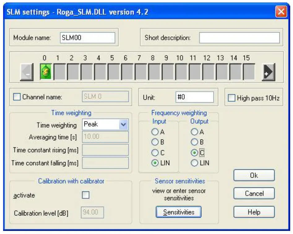
Weightings
Time weightings
The following time weightings may be selected in dialog in the combo box ‚Time weighting:
| FAST | exponential decreasing weighting of past levels with of a time constant of 125 ms |
| SLOW | exponential decreasing weighting of past levels with of a time constant of 1000 ms |
| Impulse | exponential decreasing weighting of past levels with of a time constant of 35 ms for increasing and 1500 ms for decreasing levels |
| Leq | equivalent continuous sound pressure level. Even weighting of the
levels in the time window specified (in dialog in input field ‚Averaging time [s]‘ in seconds). |
| Peak | absolute maximum of instantaneous value of sound pressure. |
| User defined | if ‘user defined’ is selected, you may specify the time constants for
increasing signals (‘Time constant rising’) and decreasing signals (‘Time constant falling’). I.E. if you specify 125 ms for ‘Time constant rising’ and 125 ms for ‘Time constant falling’ the result is the same as the time weighting FAST. |
Frequency weightings
The SLM-module is able to calculate frequency weightings A, B, C and LINEAR according to IEC 651. The accuracy depends on the sampling frequency of the input signal:
| Scan rate of input signal | Accuracy grade redeemed |
| < 30 kHz | Not recommended |
| 30 kHz | Grade 0 up to 5 kHz input signal frequency Grade 1 up to 6,3 kHz input signal frequency |
| 40 kHz .. 80
kHz |
Grade 0 up to 12,5 kHz input signal frequency Grade 1 full frequency range |
| >= 80 kHz | Grade 0 full frequency range |
Input frequency weighting
Present frequency weighting of the input signal.
| A | frequency weighting A according to IEC 651 & IEC 61672-1:2013 |
| B | frequency weighting B according to IEC 651 & IEC 61672-1:2013 |
| C | frequency weighting C according to IEC 651 & IEC 61672-1:2013 |
| LIN – Z | frequency weighting LINEAR according to IEC 651 & IEC 61672- 1:2013 |
Output frequency weighting
Desired frequency weighting of the sound level. Please note, that not all combinations of input frequency weighting and output frequency weighting are possible.
| A | frequency weighting A according to IEC 651 & IEC 61672-1:2013 |
| B | frequency weighting B according to IEC 651 & IEC 61672-1:2013 |
| C | frequency weighting C according to IEC 651 & IEC 61672-1:2013 |
| LIN Z | frequency weighting LINEAR according to IEC 651 & IEC 61672-1:2013 |
Please note that the dynamic range especially with low frequencies depends on the position of the weighting in the signal flow, whether the frequency weighting is done before or after the ADC (Analog/Digital-Converter).
An example
You have got a noise signal with portions of 100 dB at 20 Hz and 30 dB at 1 kHz and you need A-weighted level (dbA), the ADC has a full scale of 60 dB.
A-weighting filter before the ADC
The 20 Hz-Signal is damped by 50,5 dB to 49,5 dB, the 1 kHz Signal remains constant. The sum is below 60 dB and may be acquired correctly be the ADC.
The measurement may be done.
A-weighting filter after the ADC
The 20 Hz-Signal with 100 dB results in overrange for the ADC.
The Measurement cannot be done.
To take the measurement nevertheless, the full scale must be adjusted, so that the ADC can handle 100 dB. The 1 kHz portion with 30 dB-Signal is 70 dB below full scale and will be distorted by background noise. Especially, if you need A-weighting, and there are big portions at low frequencies, a hardware A-weighting before the ADC is strongly recommended.
High Pass 10 Hz
To suppress low frequency noise a high pass filter is provided. It is a two pole butterworth filter with a cut off of 10 Hz. If you check the checkbox, the filter is used, else not.
Calibration
To allow the display of noise levels in dB, the module has to be calibrated.
There are two methods to calibrate the channels of the module
Calibration using a calibrator
Check the checkbox ‘activate‘ in the group box ‘Calibration with calibrator’, enter the level of your calibrator and start a measurement.
A dialog for monitoring the status of calibration is displayed (SLM calibration‘). If more than one SLM-modules are placed on the schematic you have to perform calibration for each of them separately.
If you plug on a calibrator to one of the microphones, the level of this microphone remains constant for a while (Display ‚Level is constant xx % with xx of 0 .. 100) and using this level and the level of the calibrator given, the calibration difference is calculated and adjusted (display ‚calibration value is taken over‘ and a calibration value in the column ‚new Value‘). The calibration for this channel is finished and the calibrator may be plugged onto the next microphone until you get the display‚ calibration value is taken over‘ for all channels.
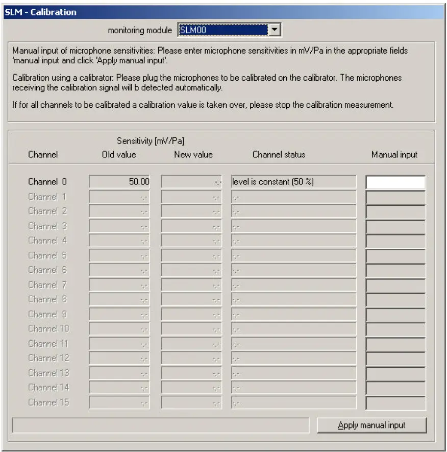
The order you calibrate the microphones does not matter. The microphone with calibrator plugged on is detected automatically by the constant level.
For microphones, without calibrator the input level varies (display ‚level is changing) and calibration is done for these channels.
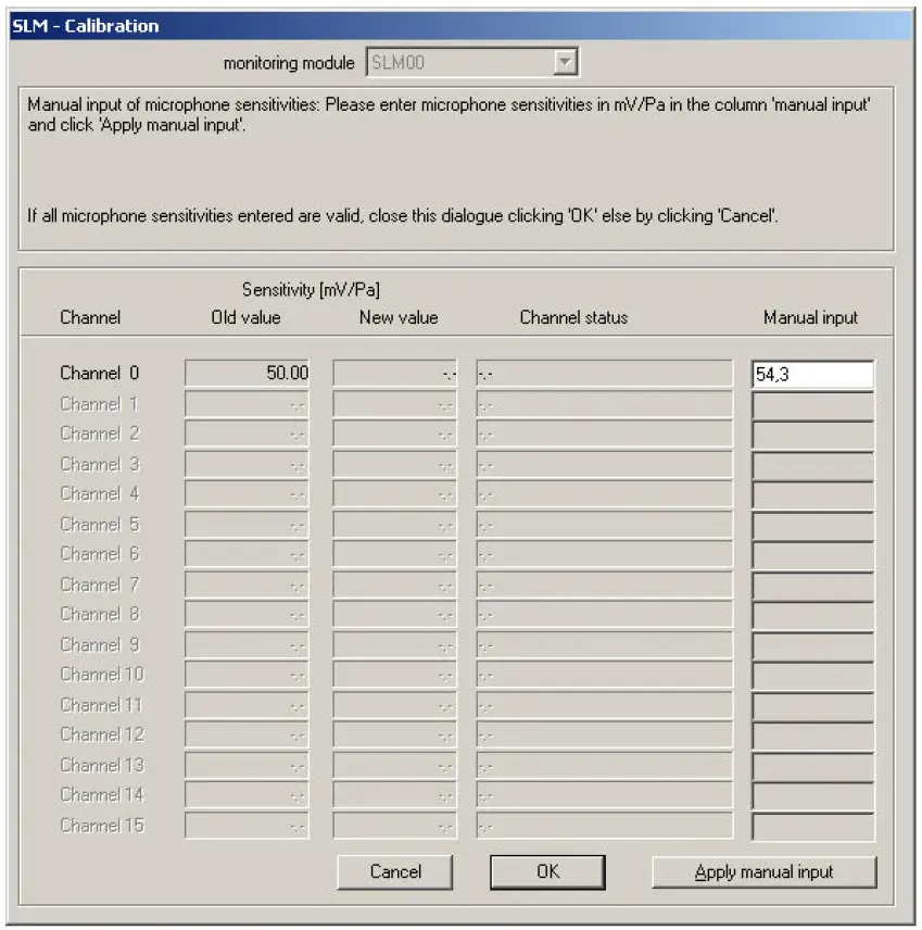
Direct input of microphone sensitivities
Click the button ‘Sensitivities’ in the group box ‘Sensor sensitivities’. The calibration dialogue will be displayed where you may view and enter the microphone sensitivities.
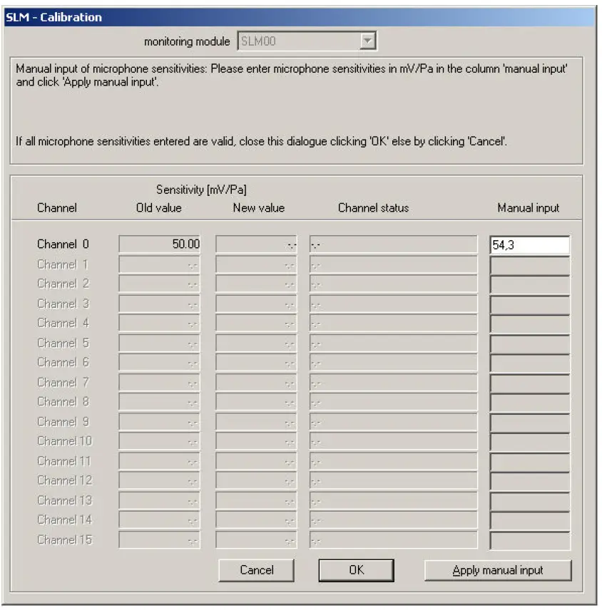
Enter the microphone sensitivities in the column ‘Manual input’ and click ‘Apply manual input’.
SPM Module
The SPM-module (Sound Power Measurement) determines the sound power from some sound pressure levels regarding all correction terms necessary.
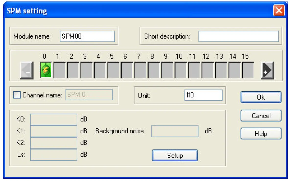
Inputs
The SPM-module has 1 to 16 inputs which may be switched on and off by the ‚+‘ – and ‚-‘ – buttons. The inputs expect levels in dB (normally coming from SLM-modules).
Output
The SPM module has one output for the sound power level.
Correction terms
For the determination of sound power according to standards, correction terms have to be regarded:
- K0 correction term for barometric pressure and temperature, see DIN 45 635, paragraph 7.1.4.
- K1 correction term for background noise, see DIN 45 635, paragraph 7.1.3.
- K2 correction term for environmental influence, see DIN 45 635, paragraph 7.1.4.
- Ls correction term for the size of the enveloping surface, see DIN 45 635, paragraphs 6.4., 7.2.
Correction term for barometric pressure and temperature K0
- Correction term for barometric pressure and temperature, see DIN 45 635, paragraph 7.1.4.
Enter the temperature in input field ‚Temperature‘ and the barometric pressure in the input field ‚Barometric Pressure‘. The correction term is displayed in the field ‚K0 Setting‘.
According to DIN 45 635, for accuracy grade 2 K0 is not necessary, in the standards ISO 374x it is not mentioned at all. Therefore you may select to use K0 or not for calculation (checkbox ‚Use K0‘).
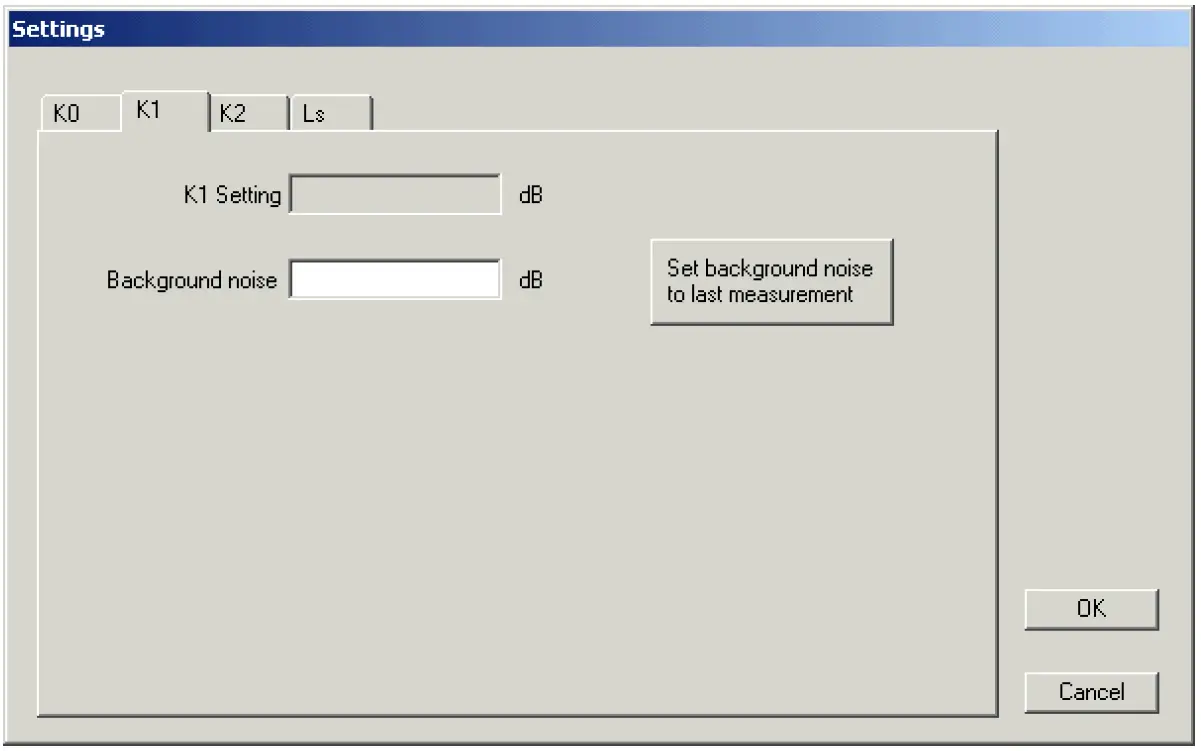
 Correction term for background noise K1
Correction term for background noise, see DIN 45 635, paragraph 7.1.3.
Take a measurement with candidate switched off. Than you may declare this sound pressures to be the background noise (button ‚Set background noise to last measurement‘), or enter the enveloping surface sound pressure level (= sound power level – Ls) of the background noise directly (input field ‚Background noise‘).
Please note, that the measurement of background noise has to be taken with the same frequency weighting as the following measurement.
The actual value of K1 depends on the signal to background noise ratio and is calculated online during measurement. If the energetic sum of information signal and background noise is less than 3 dB above the background noise, correction term K1 cannot be calculated and the output of the module is set to –1000.0 dB.
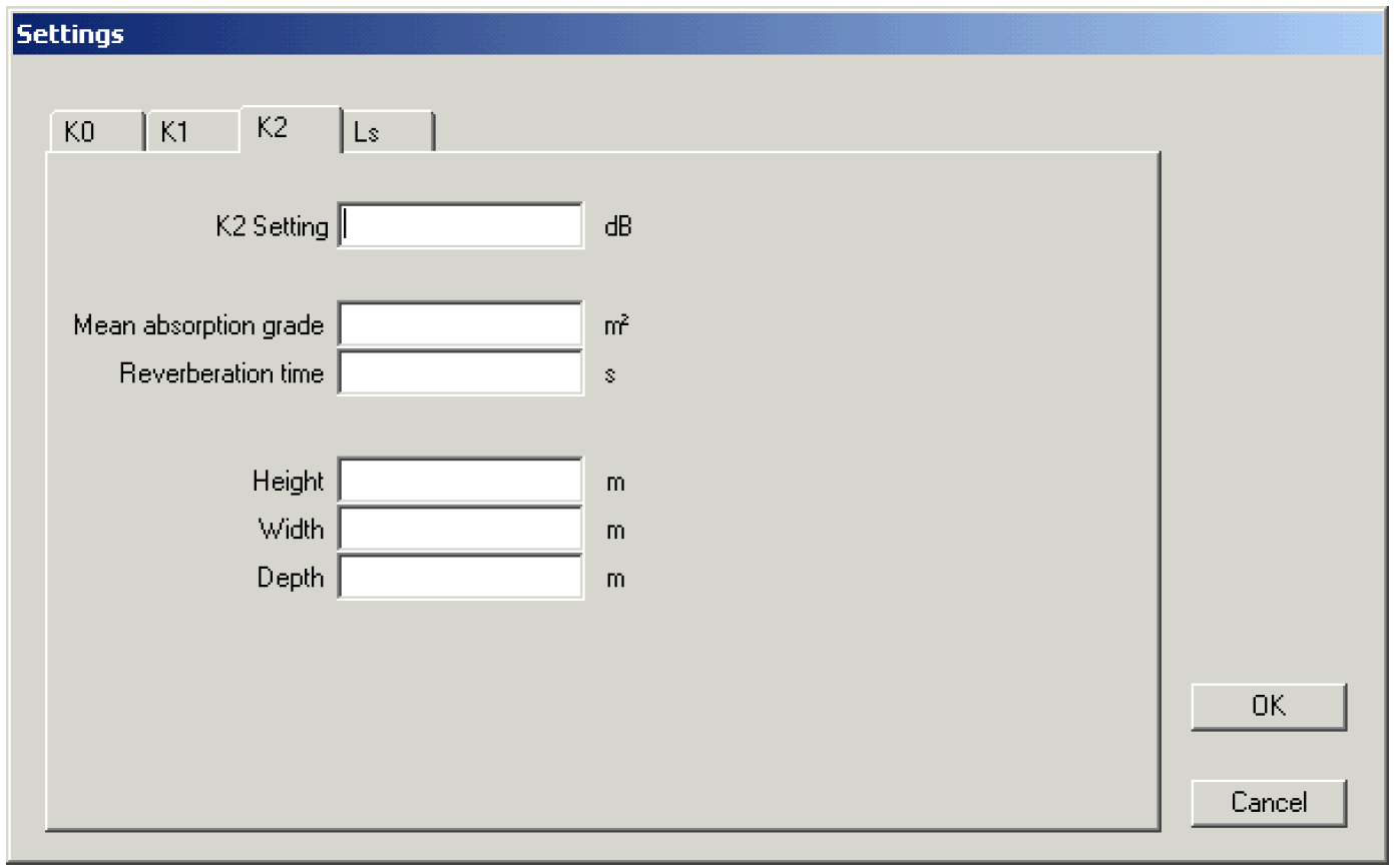
Correction term for environmental influence K2
Correction term for environmental influence, see DIN 45 635, paragraph 7.1.4. You may specify the environmental influence by two ways:
Direct input
Enter K2 directly in dB in input field ‚K2 Setting‘.
Calculation of K2 via properties of the measuring room
Enter the dimensions (height, width and depth in the input fields ‚Height‘, ‚Width‘ and ‚Depth‘) and the mean absorption coefficient (input field ‚Mean absorption grade‘)or reverberation time of test cage (input field ‚Reverberation time‘) of the test cage.
Please note, that you have to specify the correction term for the size of the enveloping surface Ls prior to evaluation of K2
Correction term for the size of the enveloping surface Ls
Correction term for the size of the enveloping surface, see DIN 45 635, paragraphs 6.4., 7.2. You may enter the ratio of the enveloping surface to 1 m² directly in dB (input field ‚Ls Setting‘) or the enveloping surface in square meters (input field ‚Enveloping surface‘, selection ‚Direct Input‘).

You may also specify the enveloping surface by its shape and dimensions:
Sphere
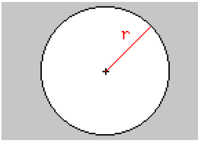
For the calculation the radius must be known.
Hemisphere
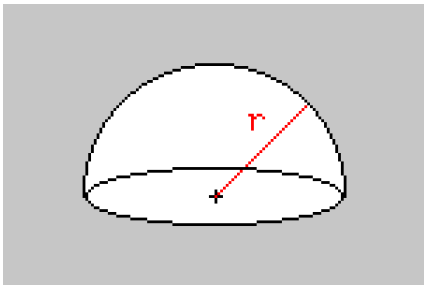
For the calculation the radius must be known
Cuboid detached
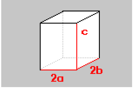
For the calculation the sides 2a, c and 2b must be known.
Cuboid at wall and ceiling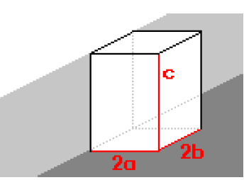
For the calculation the sides 2a, c and 2b must be known.
Cuboid at a wall
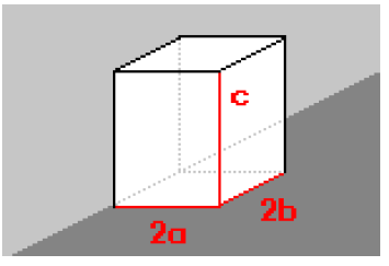
For the calculation the sides 2a, c and 2b must be known.
More Info
ROGA-Instruments, Im Hasenacker 56, D-56412 Nentershausen
- Phone: +49 (0) 6485-8815803,
- E-Mail: info@roga-instruments.com
FAQ
- Q: How do I select the appropriate time weighting in the SLM module?
- A: To select the time weighting in the SLM module, navigate to the dialog box and choose from options like FAST, SLOW, Impulse, Leq, Peak, or User defined.
- Q: What frequency weightings are supported by the SLM module?
- A: The SLM module supports frequency weightings A, B, C, and LINEAR according to IEC 651 standards.
Documents / Resources
 |
ROGA Instruments SLMOD Dasylab Add On SPM Modules [pdf] Instruction Manual SLMOD Dasylab Add On SPM Modules, SPM Modules, Modules |