![]() Neuro 102 EX
Neuro 102 EX
Enhanced Universal Single Loop
Process Controller
User Manual
Neuro 102 EX Enhanced Universal Single Loop Process Controller
This brief manual is primarily meant for quick reference to wiring connections and parameter searching. For more details on operation and application; please log on to www.ppiindia.net
FRONT PANEL LAYOUT
 Keys Operation
| Symbol | Key | Function |
| PAGE | Press to enter or exit set-up mode. | |
|
DOWN |
Press to decrease the parameter value. Pressing once decreases the value by one count; keeping pressed speeds up the change. | |
|
UP |
Press to increase the parameter value. Pressing once increases the value by one count; keeping pressed speeds up the change. | |
 |
ENTER OR ALARM ACKNOWLEDGE |
Set up Mode: Press to store the set parameter value and to scroll to the next parameter on the PAGE. Run Mode: Press to acknowledge any pending Alarm(s). This also turns off the Alarm relay. |
| AUTO MANUAL | Press to toggle between Auto or Manual Control Mode. | |
 |
(1) COMMAND | Press to access parameters that are used as Commands. |
| (1) OPERATOR | Press to access ‘Operator-Page’ parameters. | |
| (2) PROFILE | Press to access ‘Profile Run-Time Variables’. |
PV Error Indications
| Message | PV Error Type |
 |
Over-range (PV above Max. Range) |
| Under-range (PV below Min. Range) |
|
 |
Open (Sensor open / broken) |
ELECTRICAL CONNECTIONS
 ENCLOSURE ASSEMBLY
MOUNTING DETAILS
OUTPUT-5 & SERIAL COMM. MODULE
Note
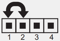
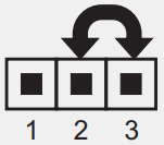
The Output-5 Module & Serial Communication Module are mounted on either side of CPU PCB as shown in figures (1) & (2) below.
JUMPER SETTINGS
INPUT TYPE & OUTPUT-1 
| Output Type | Jumper Setting – B | Jumper Setting – C |
| Relay |  |
 |
| SSR Drive |  |
 |
| DC Linear Current (or Voltage) |
 |
 |
JUMPER SETTINGS & MOUNTING DETAILS
OUTPUT-2,3 & 4 MODULE CONFIGURATION PARAMETERS: PAGE 12
| Parameters | Settings (Default Value) |
| Control Output (OP1) Type |
(Default : Relay) |
| Control Action |
Pulse PID (Default : PID) |
| Control Logic |
Direct (Default : Reverse) |
| Input Type |
Refer Table 1 (Default : Type K) |
| PV Resolution |
Refer Table 1 (Default : 1) |
| PV Units |
(Default : °C) |
| PV Range Low |
-19999 to PV Range High (Default : 0) |
| PV Range High |
PV Range Low to 9999 (Default : 1000) |
| Setpoint Low Limit |
Min. Range for the selected Input Type to Setpoint High Limit (Default : -200.0) |
| Setpoint High Limit |
Setpoint Low Limit to Max. Range for the selected Input Type (Default : 1376.0) |
| Offset for PV |
-199 to 999 or -1999.9 to 9999.9 (Default : 0) |
| Digital Filter Time Constant |
0.5 to 60.0 Seconds (in steps of 0.5 Seconds) (Default : 2.0 Sec.) |
| Sensor Break Output Power |
0 to 100 or -100.0 to 100.0 (Default : 0) |
CONTROL PARAMETERS: PAGE 10
| Parameters | Settings (Default Value) |
| Proportional Band |
0.1 to 999.9 Units (Default : 50 units) |
| Integral Time |
0 to 3600 Seconds (Default : 100 Sec.) |
| Derivative Time |
0 to 600 Seconds (Default : 16 Sec.) |
| Cycle Time |
0.5 to 100.0 Seconds (in steps of 0.5 secs.) (Default : 10.0 Sec.) |
| Relative Cool Gain |
0.1 to 10.0 (Default : 1.0) |
| Cool Cycle Time |
0.5 to 100.0 Seconds (in steps of 0.5 secs.) (Default : 10.0 sec.) |
| Hysteresis |
1 to 999 or 0.1 to 999.9 (Default : 0.2) |
| Parameters | Settings (Default Value) |
| Pulse Time |
Pulse ON Time to 120.0 Seconds (Default : 2.0 sec.) |
| ON Time |
0.1 to Value set for Pulse Time (Default : 1.0) |
| Cool Hysteresis |
1 to 999 or 0.1 to 999.9 (Default : 2) |
| Cool Pulse Time |
Cool ON Time to 120.0 Seconds (Default : 2.0) |
| Cool ON Time |
0.1 to Value set for Cool Pulse Time (Default : 1.0) |
| Heat Power Low |
0 to Power High (Default : 0) |
| Heat Power High |
Power Low to 100% (Default : 100.0) |
| Cool Power Low |
0 to Cool Power High (Default : 0) |
| Cool Power High |
Cool Power Low to 100% (Default : 100) |
SUPERVISORY PARAMETERS: PAGE 13
| Parameters | Settings (Default Value) |
| Self-Tune Command |
|
| Overshoot Inhibit |
|
| Overshoot Inhibit Factor |
1.0 to 2.0 (Default : 1.0) |
| Auxiliary Setpoint |
|
| Recorder (Retransmission) Output |
|
| SP Adjustment on Lower Readout |
|
| SP Adjustment on Operator Page |
|
| Manual Mode |
|
| Alarm SP Adjustment on Operator Page |
|
| Standby Mode |
|
| Profile Abort Command on Operator Page |
|
| Baud Rate |
|
| Communication Parity |
Even Odd (Default : Even) |
| Controller ID Number |
1 to 127 (Default : 1) |
| Communication Write Enable |
OP2 & OP3,OP4,OP5 FUNCTION PARAMETERS: PAGE 15
| Parameters | Settings (Default Value) |
| Output-2 Function Selection |
End Of Profile Cool Control (Default : None) |
| Output-2 Type |
|
| OP2 Event Status |
|
| OP2 Event Time |
0 to 9999 (Default : 0) |
| OP2 Event Time Units |
Minutes Hours (Default : Seconds) |
| Output-3 Function Selection |
Alarm End of Profile (Default : Alarm) |
| Alarm-1 Logic |
Reverse (Default : Normal) |
| OP3 Event Status |
|
| OP3 Event Time |
0 to 9999 (Default : 0) |
| OP3 Event Time Units |
| Parameters | Settings (Default Value) |
| Alarm-2 Logic |
Reverse (Default : Normal) |
| Recorder Transmission Type |
Value Setpoint (Default : Process Value) |
| Recorder Output Type |
|
| Recorder Low |
Min. to Max. Range Specified for the Selected Input Type (Default : -199) |
| Recorder High |
Min. to Max. Range Specified for the Selected Input Type (Default : 1376) |
ALARM PARAMETERS: PAGE 11
| Parameters | Settings(Default Value) |
| Alarm-1 Type |
Process Low Process High Deviation Band Window Band (Default : None) |
| Alarm-1 Setpoint |
Min. to Max. Range specified for the selected Input Type (Default : Min or Max Range) |
| Alarm-1 Deviation Band |
-999 to 999 or -999.9 to 999.9 (Default : 5.0) |
| Alarm-1 Window Band |
3 to 999 or 0.3 to 999.9 (Default : 5.0) |
| Alarm-1 Hysteresis |
1 to 999 or 0.1 to 999.9 (Default : 2) |
| Alarm-1 Inhibit |
|
| Alarm-2 Type |
Process Low Process High Deviation Band Window Band (Default : None) |
| Alarm-2 Setpoint |
Min. to Max. Range specified for the selected Input Type (Default : Min or Max Range) |
| Alarm-2 Deviation Band |
-999 to 999 or -999.9 to 999.9 (Default : 5.0) |
| Alarm-2 Window Band |
3 to 999 or 0.3 to 999.9 (Default : 5.0) |
| Alarm-2 Hysteresis |
1 to 999 or 0.1 to 999.9 (Default : 2.0) |
| Alarm-2 Inhibit |
PROFILE CONFIGURATION PARAMETERS: PAGE 16
| Parameters | Settings (Default Value) |
| Profile mode selection |
|
| Number of Segments |
1 to 16 (Default : 16) |
| Number of Repeats |
1 to 9999 (Default : 1) |
| Common Holdback |
|
| Output Off |
|
| Power Fail Strategy |
PROFILE SETTING PARAMETERS: PAGE 14
| Parameters | Settings (Default Value) |
| Segment Number |
1 to 16 (Default : 1) |
| Target Setpoint |
Min. to Max. Range specified for the selected Input Type (Default : -199) |
| Time Interval |
0 to 9999 Minutes (Default : 0) |
| Holdback Type |
|
| Holdback Value |
1 to 999 (Default : 1) |
PROFILE STATUS INFORMATION: PAGE 1
| Lower Readout Prompt | Upper Readout Information |
| |
Active Segment Number |
| Segment Type |
|
| Target Setpoint | |
| Ramping Setpoint | |
| Balance Time | |
| Balance Repeats |
ON-LINE ALTERATION PARAMETERS: PAGE 2
| Parameters | Effect on the running segment |
| Time Interval |
RAMP:- Altering the time interval shall immediately affect the ‘Ramp Rate’ for the current segment. SOAK:- Elapsed time so far is ignored and the soak timer starts counting down to 0 from the altered time interval value. |
| Holdback Type |
The modified Holdback Band Type is applied immediately on the current segment. |
| Holdback Value |
The modified Holdback Band Value is applied immediately on the current segment. |
USER LINEARISATION PARAMETERS: PAGE 33
| Parameters | Effect on the running segment |
| Code |
0 to 9999 (Default : 0) |
| User Linearisation |
|
| Total Break Points |
1 to 32 (Default : 2) |
| Break Point Number |
1 to 32 (Default : 1) |
| Actual Value for Break Point (X co-ord) |
-1999 to 9999 (Default: Undefined) |
| Derived Value for Break Point (Y co-ord) |
-1999 to 9999 (Default : Undefined) |
TABLE- 1
| Option | Range (Min. to Max.) | Resolution |
| 0 to +960°C / +32 to +1760°F | Fixed 1°C / 1°F | |
| -200 to +1376°C / -328 to +2508°F | ||
| -200 to +385°C / -328 to +725°F | ||
| 0 to +1770°C / +32 to +3218°F | ||
| 0 to +1765°C / +32 to +3209°F | ||
| 0 to +1825°C / +32 to +3218°F | ||
| 0 to +1300°C / +32 to +2372°F | ||
| Reserved for customer specific Thermocouple type not listed above. |
||
| -199 to +600°C / -328 to +1112°F -199.9 to or-199.9 to 999.9°F 600.0°C/ |
User settable 1°C / 1°F or 0.1°C / 0.1°F | |
| -1999 to +9999 units | User settable 1 / 0.1 / 0.01/ 0.001 units | |
![]() 101, Diamond Industrial Estate, Navghar,
101, Diamond Industrial Estate, Navghar,
Vasai Road (E), Dist. Palghar – 401 210.
Sales: 8208199048 / 8208141446
Support: 07498799226 / 08767395333
E: sales@ppiindia.net,
support@ppiindia.net
Jan 2022
Documents / Resources
 |
PPI Neuro 102 EX Enhanced Universal Single Loop Process Controller [pdf] User Manual Neuro 102 EX Enhanced Universal Single Loop Process Controller, Neuro 102 EX, Enhanced Universal Single Loop Process Controller, Universal Single Loop Process Controller, Single Loop Process Controller, Loop Process Controller, Process Controller, Controller |


