![]() CLS2 INSTALLATION INSTRUCTIONS
CLS2 INSTALLATION INSTRUCTIONS
With capacitance as the sensitive element, CLS sensor series continuous detects the height of the fuel level with 1mm resolution. Sensor length can also be shorten to fit tanks with different heights. With a wide range of voltage input, and easily adjustable length,
the CLS is easy to setup and works with a wide range of applications
Technical parameter:
Sensor length: 200~ 1500mm, any length available within this range
Resolution: 1mm / 5V(Input voltage is customized) / 40~+185F
Wide range of power supply: DC10V ~ 32V
Maximum operating current: < 15mA
Working temperature: -40 ~ +85
Material of the tubes: Aluminum ally
Application environment: diesel, biodiesel, gasoline, kerosene
(Not applicable to conducting medium)
Protection rank: IP65
Mode of connection:
Voltage output
Red: VCC ( 10~32V )
Black: GND
Blue: V out (0.5~4 .5V/0~3.3V/0~5V)
RS485
Red: VCC ( 10~32V )
Black: GND
Blue: B
Yellow: A
Rs232
Red: VCC ( 10~32V )
Black: GND
Blue: sensor receiving line (Rx)
Yellow: sensor sending line (Tx)
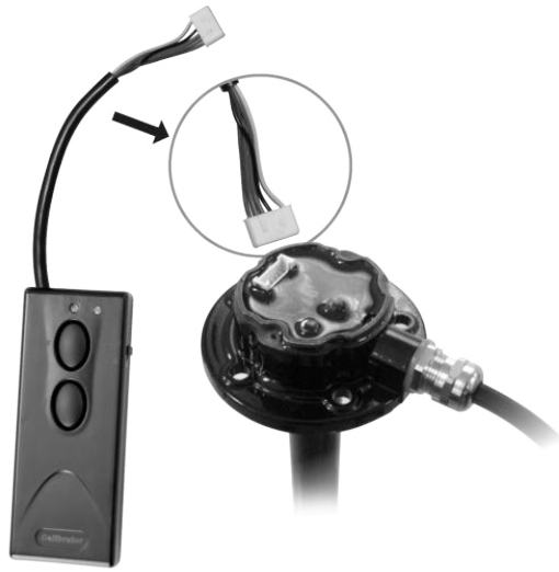
Calibrator:
Calibrator must couple with the sensor, and it has 12V/ 23A battery inside.
Red light is the power light. If the light isn’t on when switch on, battery replacement is needed;
Green light is the calibration light. Full/ Empty button is showed in above picture.
Note: Calibration is necessary before using the sensor due to different fuel types. Calibrator battery power could only used for roughly 15 times. Please change the battery when the red light becomes dark, indicating low battery.
Length adjustment and Calibration:
4.1 Adjustment of sensor length
Aluminum tube at the bottom can be shorten according to different requirements from customers.
Steps are as follows:
4.1.1 Customer specifies the sensor length according to the needs;
4.1.2 Cut the unwanted part with steel saw;
4.1.3 Remove the burrs and the debris at the cutting area with knife file to avoid short circuit;
4.1.4 Remove the plug, and assemble the rubber plug in the aluminum tube, then assemble the plastic bottom plug.
4.2 Calibration of the fuel level sensor
Calibration of the fuel sensor is calibration of the full level and empty level. The fundamental principle is to record a full value and empty value in the fuel sensor when tank is full and empty; The purpose is to define the position level of the fuel when it is full and empty in the tank. The electrical signal changes as the fuel level changes, calculating the height of the fuel level.
Note:
When the fuel sensor is shortened, it needs to be calibrated. Calibration to empty level and full level is related to the medium and the liquid level, instead of volume of the tank; this operation can be operated in room (make a container, simulate a full fuel tank by filling the container full). First, calibrate full level, then the empty level, or else the sensor could not enter the setting mode.
4.2.1 Calibration of full level
Fill the tank to desired full level, put sensor into the tank, wait for about 30 seconds until the aluminum tube of the sensor is filled with fuel, then press and hold on to the “F” button on the calibrator for 5 seconds till the green LED light slowly flickers. This indicates that calibration for full level is in progress. Release the “F” button at this moment. The green LED light will turn off in about 10 seconds, indicating that the calibration of the full level is complete.
4.2.2 Calibration of the empty level
Remove sensor from the container/tank. Place on the side. After liquid fully drains from the sensor, press and hold on to the “E” button for about 5 seconds until the green LED light starts to flicker fast. This indicates that calibration for empty level is in progress. Release the “E” button at this moment. The green LED light will turn off after about 10 seconds, indicating that calibration of the empty level is complete.
4.2.3 Calibration completion
Disconnect the calibrator after calibration is done. Connect red cable and black cable with power, calibration becomes effective when sensor is power on.
Note: 1. If press the wrong button during operation, you can switch off the calibrator and exit the mode and readjust.
2. Please ensure the calibrator is turned on at all times during calibration. Re-calibrate the sensor if power off/switch off
4.2.4 Inspection
When calibration of the full level and empty level is done, inspect the output signal of the sensor:
(RS232/RS485 output needs special equipment or connect with GPS tracker to inspect the signal output.)
If the output signal meets the values listed above, it means calibration is OK and normal operation of the sensor.
Otherwise, please check the mode of connection and re-calibrate it.
| V out | Full | 1/2 Level | Empty |
| 0~5V | 5V | 2. 5V | 0V |
| 0.5~4.5V | 4.5V | 2.5V | 0.5V |
| 0~3.3V | 3.3V | 1. 65V | 0V |
Schematic diagram of CLS sensor cutting

4.1.1 For example, if you want to cut the sensor length to L, then dimension of the cutting position is L-3.0 mm.
4.1.2 Fix the sensor with proper force, too big force will cause deformation of the casing tube.

4.1.3 Note: Inside of the tube should keep clean, burrs dropped into the tube must be cleaned, or else, there is a risk of blocking the oil drainage hole.
4.1.4 Note: When reassemble the bottom plug, ensure the rubber cover in the plug is not damaged. Assemble the rubber cover before assembling the bottom plug.

![]()
Documents / Resources
 |
PICTOR CLS2 Sensor Continuous Detects [pdf] Installation Guide CLS2 Sensor Continuous Detects, CLS2, Sensor Continuous Detects, Continuous Detects, Detects |


