MICROCHIP FPGA PolarFire Ethernet Sensor Bridge

Specifications
- Supports interfaces: 10G SFP+, HDMI 1.4, USB 2.0, Type-C UART, 2 GB DDR4 x32, MIPI Connector
- Programming: On-board FlashPro5 (FP5) programmer for PolarFire FPGA development
Introduction
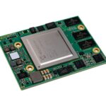
The PolarFire® Ethernet Sensor Bridge (PFSB) kit is an RoHS-compliant board that has two MIPI camera interface, two 10G SFP ports, and an HDMI interface.
The following image highlights the top-view of the PFSB kit.
Figure 1. Board Callout (Top-View)

The following image highlights the bottom-view of the PFSB kit.
Figure 2. Board Callout (Bottom-View)

For more information about the PFSB kit, see the MPF200-ETH-SENSOR-BRIDGE page.
Getting Started
The PolarFire Ethernet Sensor Bridge board supports the following interfaces:
- 10G SPF+ Ports
- X32 DDR4
- HDMI 1.4
- USB-UART
- 2x MIPI camera interface
- FMC connector
The PolarFire device is programmed using the on-board FlashPro5 (FP5) programmer. The on-board FP5 programmer is also used to develop and debug embedded applications using SoftConsole, Identify, or SmartDebug.
Kit Contents (Ask a Question)
The following table lists the contents of the PolarFire Ethernet Sensor Bridge.
Table 1-1. Kit Contents
| Item | Quantity |
| PolarFire Ethernet Sensor Bridge Board | 1 |
| PolarFire Ethernet Sensor Bridge Quickstart Card | 1 |
| 12.3 MP 477M HQ Camera Module for Raspberry Pi with 135°(D) M12 Wide Angle Lens | 1 |
| 10GBase-T SFP + RJ45 30 cm | 1 |
| 4Ft Cat7 Shielded (SSTP) 600 MHz Cable | 1 |
| 12V AC Adapter | 1 |
| 12V Power Cord | 1 |
| USB C TO USB C, USB 2.0 – 2 MET | 1 |
Block Diagram
The following block diagram shows all the components of the board.
Figure 1-1. Block Diagram

Board Overview
The following table lists the key components of the PolarFire Ethernet Sensor Bridge.
Table 1-2. Board Components
| Component | Label on Board | Description |
| Featured Device | ||
| PolarFire® FPGA MPF200T-FCG784 | U1 | See PolarFire FPGA Datasheet. |
| Power Supply | ||
| 12V external supply | J25 | The board is powered by using a 12V adapter. |
| Clocks | ||
| 50 MHz clock oscillator | X2 | 50 MHz clock oscillator with single-ended output |
| OSC | X4 | 148.5 MHz oscillator (differential LVDS output), which is the input to the XCVR1 |
| OSC | X6 | 125 MHz oscillator (differential LVDS output), which is the input to the XCVR1 |
| OSC | X5 | 125 MHz oscillator (differential LVDS output), which is the input to the XCVR3 |
| OSC | X1 | 156.25 MHz oscillator (differential LVDS output), which is the input to the XCVR2 |
| Component | Label on Board | Description |
| FPGA Programming and Debugging | ||
| Programming using on-board embedded FlashPro5 (eFP5) | U8 | On-board eFP5 to program or debug the silicon through USB to JTAG channel |
| Communication Interfaces | ||
| SFP+ Ethernet | J2 and J5 | SFP+ connector for 10G Ethernet |
| FMC connector | J1 | Expansion connector |
| HDMI | J22 | HDMI 1.4 connector |
| USB-UART | U8 | FT4232HL is a USB-to-quad UART bridge controller. This device is used to support 3 UART interfaces on the board. |
| Memory Chips | ||
| DDR4 | U2 and U3 | MT40A512M16TB-062E:R is used for DDR4 interface |
| microSD Card | J17 | microSD connector |
| General Purpose I/O | ||
| Debug push-buttons | SW1 to SW2 | For debugging |
| Dip Switches | SW8 | Eight dip switches for debugging |
| Light-Emitting Diodes (LEDs) | LED1 to LED8 | Eight active-high LEDs connected for debugging |
| Expansion Interfaces | ||
| FMC | J1 | FMC connector |
| Raspberry Pi MIPI RX Connector | J14 and J17 | Facilitates the use of the CSI-2 camera module |
Handling the Board (Ask a Question)
To avoid possible damage or malfunction, pay attention to the following points while handling or operating the board:
- Handle the board with Electrostatic Discharge (ESD) precautions to avoid damage. For information about the ESD precautions, see Understanding Product Handling and ESD Precautions.
- Turn off the board by unplugging the USB Type-C cable.
Operating Temperature (Ask a Question)
To be updated in a future revision.
Powering Up the Board (Ask a Question)
The PolarFire Ethernet Sensor Bridge board is powered by the 12V Jack (J25). To turn on the board, connect a 12V adapter to the 12V Jack (J25). Power status LEDs, VDD, VDDA, 1P2V, 1P8V, and 2P5V start glowing to indicate that the board is turned on.
The following table lists the probing points for power rails.
Table 1-3. Voltage Measurement
| S. No | Regulator/Power Rail | Jumper | Rail | Probing Point | Expected Voltage/Supply | Tolerance |
| 1 | U24/VDD | J18 (2 and 3) | VDD | VDD and GND (C308) | 1.0V | ±3% |
| 2 | J18 (2 and 1) | 1.05V | ±3% | |||
| 3 | U30/3P3V | — | 3P3V | TP_3P3V and GND (C351) | 3.3V | ±5% |
| 4 | U29/VDDA | J16 (2 and 3) | VDDA | TP_VDDA and GND (C326) | 1.0V | ±3% |
| 5 | J16 (2 and 1) | 1.05V | ±3% | |||
| 6 | U6/5P0V | — | 5P0V | 5P0V and GND (C160) | 5.0V | ±5% |
| S. No | Regulator/Power Rail | Jumper | Rail | Probing Point | Expected Voltage/Supply | Tolerance |
| 7 | U31/2P5V | — | 2P5V | 2P5V and GND (C331) | 2.5V | ±5% |
| 8 | U33/VDDI0_1 | — | 1P2V | TP_1P2V and GND (C382) | 1.2V | ±5% |
| 9 | U32/VDDI2 | J24 (9 and 10) | VDDI2 | TP_VDDI2 and GND (C363) | 3.3V | ±5% |
| 10 | J24 (7 and 8) | 2.5V | ±5% | |||
| 11 | J24 (5 and 6) | 1.8V | ±5% | |||
| 12 | J24 (3 and 4) | 1.5V | ±5% | |||
| 13 | J24 (1 and 2) | 1.2V | ±5% | |||
| 14 | U34/1P8V | — | 1P8V | TP_1P8V and GND (C397) | 1.8V | ±5% |
| 15 | U35/DDR4_VREF | — | 0P6V_VTT_DDR4 | 0P6V_VTT_DDR4 and GND (C413) | 0.6V | ±5% |
Installation and Settings
This section provides information about the software and hardware settings required to run the pre-programmed demo design on the PolarFire Ethernet Sensor Bridge.
Software Settings (Ask a Question)
Download and install the latest release of Microchip’s Libero® SoC and generate your free Silver license at Microchip Portal. The Libero SoC installer includes the required device programmerdrivers. See the following references:
- For more information about licensing and installing Libero SoC, see the Libero SoC Documentation.
- For more information about installing SoftConsole, see the SoftConsole page.
- For more information about downloading and installing Microchip’s DirectCores on the Host PC, where Libero SoC is installed, see the IP Core Tools.
- For more information about downloading and installing Microchip’s firmware drivers on the Host PC, where Libero SoC is installed, see the Firmware Catalog Documentation.
Hardware Settings (Ask a Question)
This section provides information about jumper settings, test points, and Power LEDs on the PFSB
board.
Jumper Settings (Ask a Question)
Connect the jumpers according to the settings specified in the following table.
Table 2-1. Jumper Settings
| Jumper | Description | Pin | Default Setting |
| J15 | Jumper to select the VDDAUX voltage for Bank 2 | Close pins 1 and 2 for setting VDDAUX to 2.5V. | Pins 1 and 2 are closed. |
| J24 | Jumper to select the bank voltage for GPIO Bank 2 | Close pins as follows:
• 1 and 2 = 1.2V |
Pins 9 and 10 are closed. |
| • 3 and 4 = 1.5V | |||
| • 5 and 6 = 1.8V | |||
| • 7 and 8 = 2.5V | |||
| • 9 and 10 = 3.3V |
Power Supply LEDs (Ask a Question)
The following table lists the power supply LEDs on the PFSB kit.
Table 2-2. Power Supply LEDs
| LED | Description |
| VDD | 1V rail (core voltage) |
| 1P8V | 1.8V rail |
| VDDA | 1V analog |
| 2P5V | 2.5V |
| 1P2V | 1.2V |
| 5P0V | 5V rail |
Test Points (Ask a Question)
The following test points are available on the PFSB kit.
Table 2-3. Test Points
| Test Point | Description |
| GND1 | Test point for GND |
| GND4 | Test point for GND |
| GND5 | Test point for GND |
| TP_VDDA | Test point for VDDA |
| TP_1P2V | Test point for 1.2V |
| TP_2P5V | Test point for 2.5V |
| TP_VDD | Test point for 1V (core voltage rail) |
| TP_1P8V | Test point for 1.8V |
Power Sources (Ask a Question)
The PFSB uses Microchip power supply devices. For more information about these power supply devices, see Microchip’s Power Management Devices. The following table lists the key voltage rails required for a normal operation of the PFSB board.
Table 2-4. I/O Voltage Rails
| Bank | I/O Rail | Voltage |
| Bank 0 and 1 (HSIO) | 1P2V | 1.2V |
| Bank 2 (GPIO) | VDDI2 | 1.8V, 2.5V, and 3.3V |
| Bank 4 (GPIO) | 2P5V | 2.5V |
| Bank 3 (JTAG) | 3P3V | 3.3V |
| Bank 5 (GPIO) | 1P8V | 1.8V |
The following figure shows voltage rails 5V, 3.3V, 2.5V, 1.8V, 1.2V, and 1.0V (VDD) that are available on the PFSB kit.
Figure 2-1. Voltage Rails

The following table lists the power regulators recommended for the PFSB kit voltage rails.
Table 2-5. Power Regulators
| Voltage Rail | Part Number | Description | Current |
| VDD (1V) | TPS544C25RVFT | IC REG BUCK ADJUSTABLE 20A | 20A |
| Voltage Rail | Part Number | Description | Current |
| VDDA | MIC69502WR | IC REG LINEAR POS ADJ 5A | 5A |
| VDDI0_1 | MIC26950YJL-TR | IC REG BUCK ADJUSTABLE 12A | 12A |
| VDDI2 | MIC26950YJL-TR | IC REG BUCK ADJUSTABLE 12A | 12A |
| 1P8V | MIC22405YML-TR | IC REG BUCK ADJUSTABLE 3A | 4A |
| 2P5V | MIC69502WR | IC REG LINEAR POS ADJ 5A | 5A |
| 3P3V | MIC26950YJL-TR | IC REG BUCK ADJUSTABLE 12A | 12A |
| VTT/VREF | MIC5166YML-TR | IC PWR SUP 3A HS DDR TERM 10MLF | 3A |
| 5P0V | MCP16311T-E/MNY | IC REG BUCK ADJUSTABLE 1A | 1A |
Board Components and Operation
This section describes the key components of the PFSB board and provides information about important board operations. For device datasheet, see the PolarFire FPGAs documentation page.
DDR4 Memory Interface (Ask a Question)
The DDR4 memory is connected to HSIO Bank 0 and 1. The following list provides the DDR4 memory specifications:
- Part number: MT40A512M16TB-062E:R
- Manufacturer: Micron
- X32
SPI Flash (Ask a Question)
SPI Flash is connected to the dedicated SPI interface of Bank 3. The following list provides the SPI Flash specifications:
- Part number: MT25QL01GBBB8ESF-0SIT
- Manufacturer: Micron
MAC ID EEPROM (Ask a Question)
The I2C-based Electrically Erasable Programmable Read-Only Memory (EEPROM) is connected to the GPIO Bank for storing dual MAC ID. The following list provides the EEPROM specifications:
- Part number: AT24MAC402-STUM-T
- Manufacturer: Microchip
Communication Interfaces (Ask a Question)
The PFSB kit supports the following interfaces for communication:
- Ethernet-XCVR: The PFSB kit supports two 10G SFP+ connectors. XCVR2 is connected to the SFP+ connectors. A 156.25 MHz clock is provided on the board.
- USB-to-UART Interface: The PFSB kit supports a USB-to-quad UART bridge controller device, which supports two UART interfaces. The following are the specifications:
- Part number: FT4232HL
- Manufacturer: FTDI
- UART_C and UART_D interfaces are connected to GPIO Bank 5
Expansion Capabilities (Ask a Question)
The PFSB kit has the following expansion capabilities.
- Raspberry Pi 22-Pin MIPI Connector
- HDMI Connector
- FMC Interface
Raspberry Pi 22-Pin MIPI Connector (Ask a Question)
The PFSB kit has two 22-pin Raspberry Pi MIPI camera interfaces. MIPI Camera signals are connected to GPIO Bank 4. It has four data lanes, one clock pair, and side band signals connected to Bank 5.
- Part number: 0524372271
- Manufacturer: Molex
HDMI Connector (Ask a Question)
The PFSB kit has an HDMI 1.4 interface connector. TPD12S016PWR is used for ESD protection and overcurrent protection. The following list provides the HDMI connector specifications:
- Part number: RAHHD19TR
- Manufacturer: Switchcraft Inc.
FMC Interface (Ask a Question)
The PFSB kit supports an FMC connector that allows the use of external daughter boards. ADC and DAC boards from Analog Devices are supported. XCVR1 and XCVR3 are connected to the FMC. Sideband signals are connected to GPIO Bank 2. The following daughter boards are supported:
- DAC38RF8xEVM_RevE
- LI-IMX530-SLVS-FMC_V1.01
- DC079C_AFE77xxEVM
The PolarFire Ethernet Sensor Bridge has four Debug LEDs (LED1 to LED4), which are connected to HSIO Bank 1. The following table lists the Debug LED to FPGA pin connection.
| LED Number | Pin |
| LED1 | AD18 |
| LED2 | AE18 |
| LED3 | AB19 |
| LED4 | AC18 |
Programming Scheme (Ask a Question)
The PolarFire Ethernet Sensor Bridge has an on-board FlashPro5 to program or debug the silicon through USB to JTAG channel. For more information about how to program the device, see Programming PolarFire FPGA Using the On-board FlashPro5.
Form Factor (Ask a Question)
The form factor of the PFSB kit is 6.8” × 6”, approximately.
System Reset (Ask a Question)
DEVRST_N is an input-only reset pad that allows a full reset of the chip to be asserted. The following figure shows a sample reset circuit that uses a Microchip MCP121T-315E/TT device.
Figure 3-1. Reset Circuit

50 MHz Oscillator (Ask a Question)
A 50 MHz clock oscillator, with an accuracy of ±10 ppm, is available on board. This clock oscillator is connected to the FPGA fabric to provide a system reference clock. The 50 MHz oscillator is connected to the B7 pin number of the FPGA device.
The following figure shows the 50 MHz clock oscillator interface.
Figure 3-2. 50 MHz Oscillator

Pin List (Ask a Question)
For more information about all package pins on the PolarFire FPGA device, see the Package Pin Assignment Table (PPAT).
Board Components Placement (Ask a Question)
The following silkscreen shows the top-view of the placement of various components on the board.
Figure 4-1. Silkscreen (Top-View)

 The following silkscreen shows the bottom-view of the placement of various components on the board.
Figure 4-2. Silkscreen (Bottom-View)


Demo Design (Ask a Question)
To be updated in a future revision.
Programming PolarFire FPGA Using the On-board FlashPro5 (Ask a Question)
The PolarFire Ethernet Sensor Bridge includes an on-board FlashPro5 programmer. Therefore, external programming hardware is not required to program the PolarFire device. The device is programmed with a programming .job file, using the FlashPro Express software installed on the host PC. As a prerequisite, ensure to download the latest version of FlashPro Express on the host PC.
Follow these steps to program an on-board PolarFire device:
- Connect the 12V adapter to J25.
When the board is successfully set up, the power LEDs start glowing. - Launch Flash Pro Express (FPExpress) software.
- Create a new Job project by selecting Project > New Job Project from FlashPro Express Job.
- In the New Job Project from FlashPro Express Job dialog box, complete the following steps:
- In Programming job file, click Browse and select the .job file.
- In FlashPro Express job project location, select a convenient path where the FlashPro Express project needs to be saved by clicking Browse.
A FlashPro Express project is created in the next window.
- Program the device by clicking RUN.
The RUN PASSED message is displayed to confirm the successful programming of the device. - Power cycle the board by unplugging the USB Type-C cable and reconnecting it.
Revision History (Ask a Question)
The revision history describes the changes that were implemented in the document. The changes are listed by revision, starting with the most current publication.
| Revision | Date | Description |
| A | 10/2024 | Initial revision |
Microchip FPGA Support
Microchip FPGA products group backs its products with various support services, including Customer Service, Customer Technical Support Center, a website, and worldwide sales offices. Customers are suggested to visit Microchip online resources prior to contacting support as it is very likely that their queries have been already answered.
Contact Technical Support Center through the website at www.microchip.com/support. Mention the FPGA Device Part number, select appropriate case category, and upload design files while creating a technical support case.
Contact Customer Service for non-technical product support, such as product pricing, product upgrades, update information, order status, and authorization.
- From North America, call 800.262.1060
- From the rest of the world, call 650.318.4460
- Fax, from anywhere in the world, 650.318.8044
Microchip Information
The Microchip Website
Microchip provides online support via our website at www.microchip.com/. This website is used to make files and information easily available to customers. Some of the content available includes:
- Product Support – Data sheets and errata, application notes and sample programs, design resources, user’s guides and hardware support documents, latest software releases and archived software
- General Technical Support – Frequently Asked Questions (FAQs), technical support requests, online discussion groups, Microchip design partner program member listing
- Business of Microchip – Product selector and ordering guides, latest Microchip press releases, listing of seminars and events, listings of Microchip sales offices, distributors and factory representatives
Product Change Notification Service
Microchip’s product change notification service helps keep customers current on Microchip products. Subscribers will receive email notification whenever there are changes, updates, revisions or errata related to a specified product family or development tool of interest.
To register, go to www.microchip.com/pcn and follow the registration instructions.
Customer Support
Users of Microchip products can receive assistance through several channels:
- Distributor or Representative
- Local Sales Office
- Embedded Solutions Engineer (ESE)
- Technical Support
Customers should contact their distributor, representative or ESE for support. Local sales offices are also available to help customers. A listing of sales offices and locations is included in this document.
Technical support is available through the website at: www.microchip.com/support
Microchip Devices Code Protection Feature
Note the following details of the code protection feature on Microchip products:
- Microchip products meet the specifications contained in their particular Microchip Data Sheet.
- Microchip believes that its family of products is secure when used in the intended manner, within operating specifications, and under normal conditions.
- Microchip values and aggressively protects its intellectual property rights. Attempts to breach the code protection features of Microchip product is strictly prohibited and may violate the Digital Millennium Copyright Act.
- Neither Microchip nor any other semiconductor manufacturer can guarantee the security of its code. Code protection does not mean that we are guaranteeing the product is “unbreakable”. Code protection is constantly evolving.
- Microchip is committed to continuously improving the code protection features of our products.
Legal Notice
This publication and the information herein may be used only with Microchip products, including to design, test, and integrate Microchip products with your application. Use of this information
in any other manner violates these terms. Information regarding device applications is provided only for your convenience and may be superseded by updates. It is your responsibility to ensure that your application meets with your specifications. Contact your local Microchip sales office for additional support or, obtain additional support at www.microchip.com/en-us/support/design-help/client-support-services.
THIS INFORMATION IS PROVIDED BY MICROCHIP “AS IS”. MICROCHIP MAKES NO REPRESENTATIONS OR WARRANTIES OF ANY KIND WHETHER EXPRESS OR IMPLIED, WRITTEN OR ORAL, STATUTORY OR OTHERWISE, RELATED TO THE INFORMATION INCLUDING BUT NOT LIMITED TO ANY IMPLIED WARRANTIES OF NON-INFRINGEMENT, MERCHANTABILITY, AND FITNESS FOR A PARTICULAR PURPOSE, OR WARRANTIES RELATED TO ITS CONDITION, QUALITY, OR PERFORMANCE.
IN NO EVENT WILL MICROCHIP BE LIABLE FOR ANY INDIRECT, SPECIAL, PUNITIVE, INCIDENTAL, OR CONSEQUENTIAL LOSS, DAMAGE, COST, OR EXPENSE OF ANY KIND WHATSOEVER RELATED TO THE INFORMATION OR ITS USE, HOWEVER CAUSED, EVEN IF MICROCHIP HAS BEEN ADVISED OF THE POSSIBILITY OR THE DAMAGES ARE FORESEEABLE. TO THE FULLEST EXTENT ALLOWED BY LAW, MICROCHIP’S TOTAL LIABILITY ON ALL CLAIMS IN ANY WAY RELATED TO THE INFORMATION OR ITS USE WILL NOT EXCEED THE AMOUNT OF FEES, IF ANY, THAT YOU HAVE PAID DIRECTLY TO MICROCHIP FOR THE INFORMATION.
Use of Microchip devices in life support and/or safety applications is entirely at the buyer’s risk, and the buyer agrees to defend, indemnify and hold harmless Microchip from any and all damages, claims, suits, or expenses resulting from such use. No licenses are conveyed, implicitly or otherwise, under any Microchip intellectual property rights unless otherwise stated.
Trademarks
The Microchip name and logo, the Microchip logo, Adaptec, AVR, AVR logo, AVR Freaks, BesTime, BitCloud, CryptoMemory, CryptoRF, dsPIC, flexPWR, HELDO, IGLOO, JukeBlox, KeeLoq, Kleer, LANCheck, LinkMD, maXStylus, maXTouch, MediaLB, megaAVR, Microsemi, Microsemi logo, MOST, MOST logo, MPLAB, OptoLyzer, PIC, picoPower, PICSTART, PIC32 logo, PolarFire, Prochip Designer, QTouch, SAM-BA, SenGenuity, SpyNIC, SST, SST Logo, SuperFlash, Symmetricom, SyncServer, Tachyon, TimeSource, tinyAVR, UNI/O, Vectron, and XMEGA are registered trademarks of Microchip Technology Incorporated in the U.S.A. and other countries.
AgileSwitch, ClockWorks, The Embedded Control Solutions Company, EtherSynch, Flashtec, Hyper Speed Control, HyperLight Load, Libero, motorBench, mTouch, Powermite 3, Precision Edge, ProASIC, ProASIC Plus, ProASIC Plus logo, Quiet-Wire, SmartFusion, SyncWorld, TimeCesium, TimeHub, TimePictra, TimeProvider, and ZL are registered trademarks of Microchip Technology Incorporated in the U.S.A.
Adjacent Key Suppression, AKS, Analog-for-the-Digital Age, Any Capacitor, AnyIn, AnyOut, Augmented Switching, BlueSky, BodyCom, Clockstudio, CodeGuard, CryptoAuthentication, CryptoAutomotive, CryptoCompanion, CryptoController, dsPICDEM, dsPICDEM.net, Dynamic
Average Matching, DAM, ECAN, Espresso T1S, EtherGREEN, EyeOpen, GridTime, IdealBridge,
IGaT, In-Circuit Serial Programming, ICSP, INICnet, Intelligent Paralleling, IntelliMOS, Inter-Chip Connectivity, JitterBlocker, Knob-on-Display, MarginLink, maxCrypto, maxView, memBrain, Mindi, MiWi, MPASM, MPF, MPLAB Certified logo, MPLIB, MPLINK, mSiC, MultiTRAK, NetDetach, Omniscient Code Generation, PICDEM, PICDEM.net, PICkit, PICtail, Power MOS IV, Power MOS 7, PowerSmart, PureSilicon, QMatrix, REAL ICE, Ripple Blocker, RTAX, RTG4, SAM-ICE, Serial Quad I/O, simpleMAP, SimpliPHY, SmartBuffer, SmartHLS, SMART-I.S., storClad, SQI, SuperSwitcher, SuperSwitcher II, Switchtec, SynchroPHY, Total Endurance, Trusted Time, TSHARC, Turing, USBCheck, VariSense, VectorBlox, VeriPHY, ViewSpan, WiperLock, XpressConnect, and ZENA are trademarks of Microchip Technology Incorporated in the U.S.A. and other countries.
SQTP is a service mark of Microchip Technology Incorporated in the U.S.A.
The Adaptec logo, Frequency on Demand, Silicon Storage Technology, and Symmcom are registered trademarks of Microchip Technology Inc. in other countries.
GestIC is a registered trademark of Microchip Technology Germany II GmbH & Co. KG, a subsidiary of Microchip Technology Inc., in other countries.
All other trademarks mentioned herein are property of their respective companies.
© 2024, Microchip Technology Incorporated and its subsidiaries. All Rights Reserved.
ISBN: 978-1-6683-0341-2
Quality Management System
For information regarding Microchip’s Quality Management Systems, please visit www.microchip.com/quality.
Worldwide Sales and Service
| AMERICAS | ASIA/PACIFIC | ASIA/PACIFIC | EUROPE |
| Corporate Office | Australia – Sydney
Tel: 61-2-9868-6733 China – Beijing Tel: 86-10-8569-7000 China – Chengdu Tel: 86-28-8665-5511 China – Chongqing Tel: 86-23-8980-9588 China – Dongguan Tel: 86-769-8702-9880 China – Guangzhou Tel: 86-20-8755-8029 China – Hangzhou Tel: 86-571-8792-8115 China – Hong Kong SAR Tel: 852-2943-5100 China – Nanjing Tel: 86-25-8473-2460 China – Qingdao Tel: 86-532-8502-7355 China – Shanghai Tel: 86-21-3326-8000 China – Shenyang Tel: 86-24-2334-2829 China – Shenzhen Tel: 86-755-8864-2200 China – Suzhou Tel: 86-186-6233-1526 China – Wuhan Tel: 86-27-5980-5300 China – Xian Tel: 86-29-8833-7252 China – Xiamen Tel: 86-592-2388138 China – Zhuhai Tel: 86-756-3210040 |
India – Bangalore
Tel: 91-80-3090-4444 India – New Delhi Tel: 91-11-4160-8631 India – Pune Tel: 91-20-4121-0141 Japan – Osaka Tel: 81-6-6152-7160 Japan – Tokyo Tel: 81-3-6880- 3770 Korea – Daegu Tel: 82-53-744-4301 Korea – Seoul Tel: 82-2-554-7200 Malaysia – Kuala Lumpur Tel: 60-3-7651-7906 Malaysia – Penang Tel: 60-4-227-8870 Philippines – Manila Tel: 63-2-634-9065 Singapore Tel: 65-6334-8870 Taiwan – Hsin Chu Tel: 886-3-577-8366 Taiwan – Kaohsiung Tel: 886-7-213-7830 Taiwan – Taipei Tel: 886-2-2508-8600 Thailand – Bangkok Tel: 66-2-694-1351 Vietnam – Ho Chi Minh Tel: 84-28-5448-2100 |
Austria – Wels
Tel: 43-7242-2244-39 Fax: 43-7242-2244-393 Denmark – Copenhagen Tel: 45-4485-5910 Fax: 45-4485-2829 Finland – Espoo Tel: 358-9-4520-820 France – Paris Tel: 33-1-69-53-63-20 Fax: 33-1-69-30-90-79 Germany – Garching Tel: 49-8931-9700 Germany – Haan Tel: 49-2129-3766400 Germany – Heilbronn Tel: 49-7131-72400 Germany – Karlsruhe Tel: 49-721-625370 Germany – Munich Tel: 49-89-627-144-0 Fax: 49-89-627-144-44 Germany – Rosenheim Tel: 49-8031-354-560 Israel – Hod Hasharon Tel: 972-9-775-5100 Italy – Milan Tel: 39-0331-742611 Fax: 39-0331-466781 Italy – Padova Tel: 39-049-7625286 Netherlands – Drunen Tel: 31-416-690399 Fax: 31-416-690340 Norway – Trondheim Tel: 47-72884388 Poland – Warsaw Tel: 48-22-3325737 Romania – Bucharest Tel: 40-21-407-87-50 Spain – Madrid Tel: 34-91-708-08-90 Fax: 34-91-708-08-91 Sweden – Gothenberg Tel: 46-31-704-60-40 Sweden – Stockholm Tel: 46-8-5090-4654 UK – Wokingham Tel: 44-118-921-5800 Fax: 44-118-921-5820 |
| 2355 West Chandler Blvd. | |||
| Chandler, AZ 85224-6199 | |||
| Tel: 480-792-7200 | |||
| Fax: 480-792-7277 | |||
| Technical Support: | |||
| www.microchip.com/support | |||
| Web Address: | |||
| www.microchip.com | |||
| Atlanta | |||
| Duluth, GA | |||
| Tel: 678-957-9614 | |||
| Fax: 678-957-1455 | |||
| Austin, TX | |||
| Tel: 512-257-3370 | |||
| Boston | |||
| Westborough, MA | |||
| Tel: 774-760-0087 | |||
| Fax: 774-760-0088 | |||
| Chicago | |||
| Itasca, IL | |||
| Tel: 630-285-0071 | |||
| Fax: 630-285-0075 | |||
| Dallas | |||
| Addison, TX | |||
| Tel: 972-818-7423 | |||
| Fax: 972-818-2924 | |||
| Detroit | |||
| Novi, MI | |||
| Tel: 248-848-4000 | |||
| Houston, TX | |||
| Tel: 281-894-5983 | |||
| Indianapolis | |||
| Noblesville, IN | |||
| Tel: 317-773-8323 | |||
| Fax: 317-773-5453 | |||
| Tel: 317-536-2380 | |||
| Los Angeles | |||
| Mission Viejo, CA | |||
| Tel: 949-462-9523 | |||
| Fax: 949-462-9608 | |||
| Tel: 951-273-7800 | |||
| Raleigh, NC | |||
| Tel: 919-844-7510 | |||
| New York, NY | |||
| Tel: 631-435-6000 | |||
| San Jose, CA | |||
| Tel: 408-735-9110 | |||
| Tel: 408-436-4270 | |||
| Canada – Toronto | |||
| Tel: 905-695-1980 | |||
| Fax: 905-695-2078 |
FAQ
- Q: How do I program the PolarFire FPGA using the on-board FlashPro5?
A: To program the FPGA, connect the board to a computer via USB and use the FlashPro5 programmer software to load the programming files. - Q: What applications can be developed using SoftConsole, Identify, or SmartDebug?
A: These tools can be used to develop and debug embedded applications for the PolarFire device.
Documents / Resources
 |
MICROCHIP FPGA PolarFire Ethernet Sensor Bridge [pdf] User Guide FPGA PolarFire Ethernet Sensor Bridge, FPGA, PolarFire Ethernet Sensor Bridge, Ethernet Sensor Bridge, Sensor Bridge |