Haltech uC-10 Display Dash Kit

Specifications
- Product Name: Haltech uC-10 Display Dash
- Display: 10-inch full-color TFT screen
- Compatibility: Haltech ECUs, OBD2, selected aftermarket ECU brands
- Features: Optically bonded display, CAN compatibility, low-profile design
Product Usage Instructions
Overview
The Haltech uC-10 Display Dash is a state-of-the-art digital dash designed to provide real-time vehicle data monitoring with its 10-inch display.
Installation
To install the uC-10 Display Dash:
- Connect the main connector harness to the corresponding connector on the back of the dash.
- Attach the DTM-4 to DTM-4 CAN extension cable to the main connector harness.
- Connect the other end of the DTM-4 cable to your Haltech ECU or CAN OBD-II port.
Power Up
The uC-10 Display Dash requires a CAN connection to power up. Ensure proper grounding for ignition power and immediate activation once the Haltech ECU receives power.
uC-10 DISPLAY DASH OVERVIEW
- Innovation meets style with the latest addition to the Haltech digital dash lineup, the Haltech uC-10 Display Dash. This state-of-the-art digital dash is set to revolutionize the automotive world with its perfect blend of technology and design.
- The Haltech uC-10 features a 10-inch low-profile display that provides ample screen space for all your vital vehicle data, making it easy to monitor performance, diagnostics, and more in real-time. The full-color TFT screen is optically bonded for clear visibility, even in bright sunlight, and the stylish display adds a touch of sophistication to any vehicle.
- With its CAN compatibility with Haltech ECUs, OBD2, and selected aftermarket ECU brands, the Haltech uC-10 offers versatility that ensures seamless integration into a wide range of vehicles and setups. This makes it an invaluable tool for both professionals and hobbyists alike.
- This quick start guide will walk you through the installation of a Haltech uC-10 Display Dash into a vehicle already fitted with a Haltech ECU or equipped with a CAN OBD-II port.
- For any questions or technical support regarding this product, you can contact Haltech using the contact details at the end of this guide.
- Alternatively, scan the QR code below to access the Haltech Knowledge Base and technical support page.
 Scan this QR code to access more information about the Haltech uC-10 Display Dash.
FRONT VIEW

What’s in the box?
- Haltech uC-10 10-inch Color Display Dash
- 34 pin main connector harness and spare pins
- DTM-4 to DTM-4 CAN cable – 3000mm (120”)
- USB-A to USB-C cable
- 3 x Mounting screws (M5x8mm)
- 2 x momentary switches, pre-terminated with cables (22AWG, 800mm)
- Glass mount Wi-Fi antenna
- USB-C Dust Cap
- Quick start guide

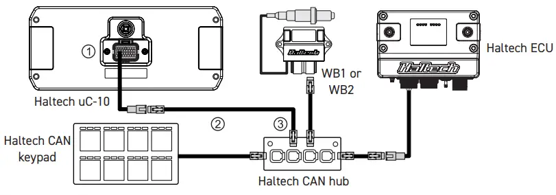
uC-10 CAN CONNECTION
Haltech CAN connection and initial power up
- The uC-10 Display Dash requires a CAN connection to a Haltech ECU, a CAN OBD-II port, or a supported third-party ECU to power up.
- To connect to a Haltech Elite or Nexus ECU:
- Connect the supplied main connector harness, featuring a 34-pin Superseal connector, to the corresponding 34-pin connector located at the back of the dash.
- Attach the DTM-4 to DTM-4 CAN extension cable to the main connector harness’s DTM-4 connector.
- Proceed to run the other end of the DTM-4 cable and connect it to your Haltech ECU, an unused port on your Haltech WB1/WB2, or an unused port on your Haltech CAN hub.
- The Haltech CAN connection not only provides ignition power but also ensures proper grounding. As a result, the dash will activate immediately once the Haltech ECU receives power (e.g., turning the ignition key to the “on” position).
- This streamlines the integration, allowing for quick and efficient operation of the uC-10 Display Dash.


NOTE: If your Haltech Nexus or Elite ECU has two or more CAN channels, it’s important to ensure that the uC-10 Display Dash is connected to a CAN channel configured to use the Haltech CAN protocol. If this protocol is not enabled, the dash will power up but will not display any ECU data.
To connect to a Haltech Platinum Series ECU:
- If you are using a Haltech Platinum Series ECU, an additional CAN cable adapter is required to convert the DTM-4 plug to an 8-pin Tyco connector. This cable is included with the ECU upon purchase and can also be bought separately if you need a new one (HT-130040).
CAN OBD-II connection
- To connect the uC-10 to a vehicle that uses CAN OBD-II, it is recommended to use a HT-135003 OBD-II to DTM-4 CAN Cable (sold separately) to read and display data from the vehicle’s OBD-
II system. Apart from being a communications cable, this cable also provides +12V to the dash display. The red power wire should be connected to a switched +12V ‘Key On’ power source in
the vehicle, since the vehicle’s OBD-II connector supplies constant 12V even when the key is off. For more information on where to connect this wire, please refer to your vehicle’s wiring diagram. - Need information on connecting the uC-10 Display Dash to supported third-party ECUs or wiring as a standalone dash? Scan the QR code located on page 2 to access the Knowledge Base.

NEXUS SOFTWARE PROGRAMMER
Installing the NSP software
Haltech NSP (Nexus Software Programmer) is the software used for setting up and configuring the uC-10 Display Dash. Follow these steps to install the Haltech NSP software:
- Download the NSP installer – Go to the Haltech website (www.haltech.com), navigate to the ‘Downloads’ section, and click on the download link.

- Run the installer file – Once the download is complete, locate the downloaded file (usually in the ‘Downloads’ folder of your computer) and double-click on the file to run the Nexus Software Setup Wizard.
- Launch Haltech NSP – Once the installation is complete, you can launch the Haltech NSP software from the Windows ‘Start’ menu or using the desktop shortcut that was created.

Going online with the dash display
With the NSP software open and the dash powered up, connect the supplied Haltech USB cable from your laptop to the USB-C port on the front of the uC-10 Display Dash.
- The USB connection enables the NSP software to automatically recognize the uC-10 Display Dash and establish a connection. The software allows you to further configure the display beyond the default settings. This includes customizing screens, configuring warnings and alarms, or assigning inputs and outputs to sensors or devices that you plan to wire directly to the dash.
- The NSP software displays dash data in real-time and applies changes to the dash screen as soon as you make adjustments in the software. This makes the dash setup easier, more intuitive, and a more refined experience.

Wi-Fi COMMUNICATIONS
Setting up Wi-Fi communications (Now available with firmware version 2.27.0 or later.)
- Wi-Fi communication is another method for connecting the uC-10 Display Dash to your laptop, serving as an alternative to a USB connection once the Wi-Fi module is enabled.
- To set up your Wi-Fi connection, follow these steps:
- Open NSP and connect your uC-10 Display Dash using the provided USB-C cable.
- Click on ‘Connections’ in the navigation tree and enable the Wi-Fi module.
- Under ‘Connections’, select ‘Wi-Fi’ to set up your SSID and password. Note that your SSID must be at least 1 character long, and your password at least 8 characters.
- Click ‘Apply’.
- Power up the dash using main power (ignition switch on), then go to your computer’s Network settings. Connect to your uC-10 Display Dash by selecting your chosen SSID and entering your password.
NOTE: The Wi-Fi hardware and antenna are included, but Wi-Fi functionality will not be available in the initial release. Update to firmware version 2.27.0 or later, to enable this functionality.

MOUNTING TEMPLATE


| PIN | FUNCTION |
| 1 | CAN High |
| 2 | CAN Low |
| 3 | +12V switched input |
| 4 | Battery ground |
| 5 | +5V output |
| 6 | AVI 10 (Button 1) |
| 7 | Unused |
| 8 | Unused |
| 9 | Unused |
| 10 | Unused |
| 11 | Unused |
| 12 | +12V switched output |
| 13 | Ground for buttons |
| 14 | Ground for buttons |
| 15 | SPI 4 (Button 2) |
| 16 | Alternator Excite |
| 17 | AVI 9 (Park Lights) |
| PIN | FUNCTION |
| 18 | AVI 1 (Fuel Level) |
| 19 | AVI 2 |
| 20 | AVI 3 |
| 21 | AVI 4 |
| 22 | AVI 5 (Left Indicator) |
| 23 | AVI 6 (Right Indicator) |
| 24 | AVI 7 (Handbrake) |
| 25 | AVI 8 (High Beam) |
| 26 | DPO 1 |
| 27 | DPO 2 |
| 28 | DPO 3 |
| 29 | DPO 4 |
| 30 | Signal ground |
| 31 | SPI 3 |
| 32 | SPI 2 |
| 33 | SPI 1 |
| 34 | Tacho input |
uC-10 PINOUT INFORMATION
How to place pins into the connector:
- Crimp the pin onto the wire.
- Push the bottom tab to unlock.
- Insert the pin into harness side of connector.
- Push the top tabs to lock.
VOTE: Use crimper set HT-070300. Please remember soldering the wire into the pin is not recommended.

 VIDEO: How to crimp like a pro
uC-10 DISPLAY DASH WIRING
uC-10 Main Power and Ground
- For proper dash display operation or connectivity to the NSP software, ensure that the uC-10 Display Dash is powered on through pin 3 (switched +12V power) and pin 4 (ground).
- In most applications, these power and ground pins are connected to and powered by the Haltech ECU CAN system using the DTM-4 to DTM-4 cable included with the dash.
- For CAN OBD-II applications, the power and ground connections are linked to the factory OBD-II connector but utilizing a Haltech CAN OBD-II cable to supply switched +12V to the dash.

- Pin 1: CAN high
- Pin 2: CAN low
- Pin 3: Switched +12v
- Pin 4: Battery ground
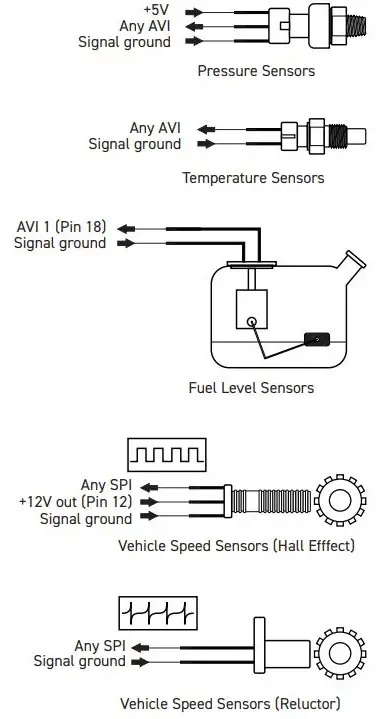
Analog Voltage Inputs (AVI)
- Number of user definable channels: 10
- Analog Voltage Inputs (AVIs) are inputs that accept variable voltage signals ranging from 0-5V, typical of pressure, temperature, and position sensors. These inputs can also accommodate switch signals that alternate between two distinct voltage levels.
- AVIs feature a software-selectable 1K-ohm
- pull-up resistor to 5V, which is typically enabled for temperature-related sensors and switched to ground inputs. They are usually disabled for sensors with an external +5V supply, such as pressure sensors or throttle position sensors. Additionally, the uC-10 features a software-selectable dual pull-up option for AVI 1, which can utilize a 240-ohm pull-up resistor. This option is ideally matched for fuel level sensors, providing enhanced flexibility for diverse sensor calibrations.
Synchronized Pulsed Inputs (SPI)
- Number of user definable channels: 4
- Synchronized Pulsed Inputs are capable of measuring the duty cycle or frequency of a signal, in addition to measuring analog voltages and switch states like AVIs. These inputs are suitable for various sensors, including wheel speed sensors or flex fuel composition sensors, with a software-selectable 1K-ohm pull-up resistor to 5V, if the sensor requires.
- SPIs are compatible with both digital (hall effect or optical) and analog (relectance) sensors. They have a maximum input voltage rating of 25V and can measure frequencies up to a maximum of 15 kHz.
Digital Pulsed Outputs (DPO)
- Number of user definable channels: 4
- Digital Pulsed Outputs (DPOs) have the capability to control relays or low-current solenoids (with a maximum of 3A) with varying duty cycles, frequencies, or switched states (On or Off). When the output is activated by the dash, the DPO pin switches to ground. Therefore, any device connected to it should be wired to respond to a ground signal when triggered.

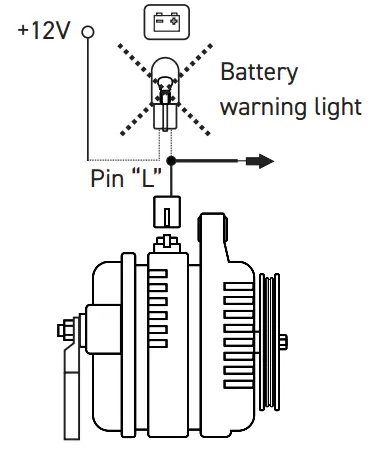
Alternator Excite Pin
- The Haltech uC-10 display dash features a dedicated alternator excite pin, which can be utilized when the uC-10 completely replaces the factory dash/gauge cluster. The excite (or exciter) pin on an alternator primarily functions to provide the initial electrical current required to initiate the alternator charging process. Typically, this current is supplied through the battery warning light on a factory dash/gauge cluster to the alternator excite pin.
- If the factory dash/gauge cluster is removed, the connection to the alternator excite pin is lost, potentially causing the alternator not to charge. In such applications, the alternator excite pin on the uC-10 can be wired to the alternator, serving as a replacement for the warning lamp or the need to wire external resistors.
Tacho Input
- The Haltech uC-10 display dash includes a dedicated tacho input pin, which can be utilized when a “wired” connection for a tachometer signal is needed. That is, the tacho signal is not transmitted to the dash digitally via the CAN signal.
- This wired tachometer connection supports both digital square wave signals, and an ignition coil negative type of signal – which is typically for applications using an external ignition module or distributor ignition with contact points.

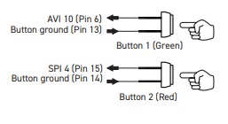
External Push Buttons
- The uC-10 Display Dash comes supplied with two push buttons that you can install in a convenient location in your vehicle. These buttons can be connected to the uC-10 main connector so that Button 1 cycles through the multiple screen display options on the uC-10 display dash, and Button 2 cancels alarms. Alternatively, you can use both buttons for screen scrolling, with one button advancing to the next screen and the other returning to the previous screen.
- To use these buttons, connect the black wires to Pin 13 and Pin 14 (ground pins for buttons), and then connect the other wires to AVI 10 and SPI 4 (button signal) on the uC-10’s 34-pin main connector as shown below.
Indicators and Warning Lights
- For street/on-road applications, wiring signals for indicators or turn signals, and warning lights is imperative. To wire these, connect the corresponding AVIs shown below to the existing wiring for these signals in the vehicle. Each of these AVIs is preassigned to indicator or warning light functions in the NSP software by default.
- Additionally, ensure to configure the voltage thresholds for when the signals switch on or off, ensuring the indicator or warning light displays correctly.


uC-10 MOUNTING OPTIONS
Moulded Panel Mount
HT-060091
Bolts directly to the back of your uC-10 dash display using three mounting screws provided. The dimensions are 500mm (20”) x 250mm (10”), which can be trimmed to fit a variety of cluster surrounds.
Standard Dash Mount
HT-060070
The standard dash mount directly bolts to the back of your uC-10 dash display using three provided screws, enabling installation at a 90° angle from a flat surface or mounting point.


Tube Mount HT-060072
Used with the standard dash mount, this allows you to install the uC-10 display dash onto a roll cage or steering column with an outer tube diameter of 31.75mm (1.25”).

uC-10 DISPLAY DASH SPECIFICATIONS

| SPECIFICATION | DETAILS |
| Display Size | 10-inch, optically bonded overlay |
| Viewing Angle | 70° Minimum (vertical and horizontal) |
| Luminance | 600+ lumens (dimmable) |
| Resolution | 1280 x 480 |
| Dimensions | 291.2mm x 126.0mm x 26.0mm (excluding rear connectors) |
| Connectors | 34 Pin AMP Superseal (Type 2 keyway)
Female RP-SMA (Wi-Fi Antenna connection) |
| Inputs and Outputs | 10 x Analog voltage inputs (AVIs)
4 x Synchronized pulsed inputs (SPIs) 4 x Digital pulsed outputs (DPOs) 1 x 5V output, 1 x 12V output, and 1 x signal ground Tachometer input pin (for wired tacho signal) Alternator excite pin 2 x Ambient light sensors (onboard) |
| Communications | CAN (Haltech, OBD-II, or supported third party ECU) USB-A (laptop) to USB-C (dash) connection
Wi-Fi (Future firmware update required) |
| Operating Voltage | 6.5V to 20.0V |
| Ambient Temperature | -10°C (14°F) to +80°C (176°F) |
| Onboard Datalogging | 512MB |
| Odometer | 6 digits |
| IP Rating | IP64 (Dust-tight and protected against water splashes) |
WARRANTY CERTIFICATE
At Haltech we make every effort to design and manufacture fault-free products that perform up to or above the market expectations. All our products are covered by a Limited 12 Month Warranty.
Haltech Limited Warranty
- Unless specified otherwise, Haltech warrants its products to be free from defects in mate-rial or workmanship for a period of 12 months from the date of purchase.
- If the Haltech product is found to be defective as mentioned above, it will be replaced or repaired if returned prepaid along with proof of purchase. Proof of purchase in the form of a copy of the original purchase invoice, receipt or bill of sale which indicates that the product is within the warranty period, must be presented to obtain warranty service.
- Replacement or repair of a defective product shall constitute the sole liability of Haltech. To the extent permitted by law, the foregoing is exclusive and in lieu of all other warranties or representations, either expressed or implied, including any implied warranty of merchant-ability or fitness. In no event shall Haltech, be liable for special or consequential damages.
Product Returns
- Please include a copy of the original purchase invoice, receipt or bill of sale along with the unused, undamaged product and its original packaging. Any product returned with missing accessory items or packaging will incur extra charges to return the item to a re-saleable condition.
- All product returns must be sent via a freight method with adequate tracking, insurance and proof of delivery services. Haltech will not be held responsible for product returns lost during transit.
- Returns of Products Supplied in Sealed Packaging
- The sale of any sensor or accessory supplied in sealed packaging is strictly non-refundable if the sealed packaging has been opened or tampered with. This will be clearly noted on the product packaging. If you do not accept these terms please return the sensor in its original unopened packaging within 30 days for a full refund.
- A sensor or accessory product may be returned after 30 days of purchase (with its sealed packaging intact) for credit only (no refunds given) and will be subject to a 10% restocking fee.
Installation of Haltech Products
- No responsibility whatsoever is accepted by Haltech for the fitment of Haltech Products. The onus is clearly on the installer to ensure that both their knowledge and the parts selected are correct for that particular application. Any damage to parts or consequential damage or costs resulting from the incorrect installation of Haltech products are totally the responsibility of the installer.
- Always disconnect the battery when doing electrical work on your vehicle. Avoid sparks, open flames or use of electrical devices near flammable substances. Do not run the en-gine with a battery charger connected as this could damage the ECU and other electrical equipment.
- Do not overcharge the battery or reverse the polarity of the battery or any charging unit. Disconnect the Haltech ECU from the electrical system whenever doing any welding on the vehicle by unplugging the wiring harness connector from the ECU.
- After completing the ECU installation, make sure there is no wiring left un-insulated. Un-insulated wiring can cause sparks, short circuits and in some cases fire. Before attempting to run the engine ensure there are no leaks in the fuel system.
- All fuel system components and wiring should be mounted away from heat sources, shielded if necessary and well ventilated. Always ensure that you follow workshop safety procedures. If you’re working underneath a jacked-up car, always use safety stands!
Haltech Off-Road Usage Policy
- In many states it is unlawful to tamper with your vehicle’s emissions equipment.
- Haltech products are designed and sold for sanctioned off-road/competition, non-regis-tered or non-emissions controlled vehicles only and may never be used on a public road or highway. Using Haltech products for street/road use on public roads or highways is prohibited by law unless a specific regulatory exemption exists (more information can be found on the SEMA Action Network website www.semasan.com/emissions for state by state details in the USA).
- It is the responsibility of the installer and/or user of this product to ensure compliance with all applicable local and federal laws and regulations. Please check with your local vehicle authority before purchasing, using or installing any Haltech product.
Haltech Australia
- 17 Durian Place, Wetherill Park NSW 2164 Australia
- Phone: +61 2 9729 0999 Email: sales@haltech.com
Haltech New Zealand
- 9/B Weza Lane, Kumeu 0810 New Zealand
- Phone: +64 988 706 16 Email: nz-sales@haltech.com
Haltech USA East
- 750 Miles Point Way, Lexington, KY USA 40510 Phone: (888) 298 8116 Email: usa@haltech.com
- Haltech USA West
- Race Winning Brands, 10800 Valley View Street, Cypress, CA 90630 Phone: (888) 298 8116 Email: usa@haltech.com
Haltech UK
- Unit 1, Miras Business Estate, Keys Park Road, Hednesford, WS12 2FS
- Phone: +44 121 285 6650 Email: uk-sales@haltech.com
- Haltech Europe Ottogasse 2A, 2333 Leopoldsdorf, Austria Phone: +43 720 883968 Email: europe@haltech.com
FAQS
Q: What should I do if my Haltech Nexus or Elite ECU has multiple CAN channels?
A: Ensure that the uC-10 Display Dash is connected to a CAN channel configured to use the Haltech CAN protocol for proper display of ECU data.
Documents / Resources
 |
Haltech uC-10 Display Dash Kit [pdf] User Guide HT-068000, uC-10 Display Dash Kit, Display Dash Kit, Dash Kit |