Danfoss AME (-H) 610 Actuators Without Safety Function

Product Specifications
| Valve type | DN | PN | Medium | Tmax Medium |
|---|---|---|---|---|
| VFG 2 | 15-125 | – | – | – |
| VFG 21 | 15-125 | – | – | – |
| VFG 25 | 15-125 | – | – | – |
Safety Notes
Prior to assembly and commissioning to avoid injury of persons and damages of the devices, it is absolutely necessary to carefully read and observe these instructions.
Necessary assembly, start-up, and maintenance work must be performed only by qualified, trained and authorized personnel.
Prior to assembly and maintenance work on the controller, the system must be:
- depressurized,
- cooled down,
- emptied and
- cleaned.
Please comply with the instructions of the system manufacturer or system operator.
Do not remove the cover before the power supply is fully switched off.
Disposal instruction
- This product should be dismantled and its components sorted, if possible, in various groups before recycling or disposal.
- Always follow the local disposal regulations.
Definition of Application
The electrical actuator is used in connection with the following valves: VFG 2(21), VFG 25, VFU 2, VFGS 2, AFQM.
Fields of application are the temperature control of water, water-glycol mixtures and steam for heating, district heating and cooling systems.
Overview Actuators AME 6..
| 610/30 | 613/33 | (-H )613/33 | |
| Safety function | – | + | + |
| Mechanical adjustment | – | – | + |
Dimensions, Weights ❶
Flanges: Connection dimensions acc. to EN 1092-2

| Valves | DN | 15 | 20 | 25 | 32 | 40 | 50 | 65 | 80 | 100 | 125 | 150 | 200 | 250 | |
| VFG(S) | L | mm | 130 | 250 | 260 | 280 | 200 | 230 | 290 | 310 | 350 | 400 | 480 | 600 | 730 |
| B | mm | 212 | 212 | 238 | 238 | 240 | 240 | 275 | 275 | 380 | 380 | 326 | 354 | 404 | |
| Weight | kg | 7 | 9 | 10 | 13 | 17 | 22 | 33 | 41 | 60 | 79 | 85 | 145 | 228 | |
| VFG(S)
Tmax 300 |
B1 | mm | – | – | – | – | – | – | – | – | – | – | 630 | 855 | 1205 |
| Weight | kg | – | – | – | – | – | – | – | – | – | – | 140 | 210 | 300 | |
| VFU 2 | B | mm | 95 | 95 | 106 | 106 | 123 | 123 | 135 | 135 | 165 | 165 | – | – | – |
| C | mm | 311 | 311 | 337 | 337 | 339 | 339 | 374 | 374 | 479 | 479 | – | – | – | |
| Weight | kg | 7 | 9 | 10 | 13 | 17 | 22 | 33 | 41 | 60 | 79 | – | – | – | |

| DN | 65 | 80 | 100 | 125 | |
| L | (mm) | 290 | 310 | 350 | 400 |
| A | 600 | 610 | – | – | |
| B | 425 | 425 | 530 | 530 | |
Valve Types for AME(-H) 6..
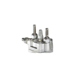
The electrical actuator AME(-H) 6.. can be mounted on the following valves, see ❷.

Mounting
Permissible Installation Positions ❸
- DN 15-50 (T max < 120oC):
- valve type AFQM – DN 15-80 (T max < 120oC):
- valve types VFG 2, VFG 21, VFG 25, VFU 2
- DN 15-250 (T max > 120 oC) all allowed valve types
- DN 65-125 (T max < 120oC): valve type AFQM
- DN 100-250 (T max < 120oC): valve types VFG 2, VFG 21, VFU 2
- DN 15-250: valve type VFGS 2 (steam).


Valve Installation ❹
- Install strainer in front of valve.
- Rinse system before installing valve.
- Observe flow direction ① on the valve body
Flanges ② in the pipeline system must be in parallel direction, the sealing surfaces must be clean and undamaged. - Install valve.
- Tighten screws crosswise in 3 steps up to the maximum torque.

Actuator and Valve Installation ❺
Before mounting:
- Carry out the electrical connection procedure acc. to the next paragraph
- turn the rotary switch to the postion “OPEN” ① to run the actuator stem ② completely back

Valves DN 150-250
- For valves DN 150 – 250 the stem of the actuator must be screwed into the valve stem.
- Observe the Installation Instructions ③ attached to valves DN 150-250.
Valves DN 15-125
- Place actuator on the valve and align.
- Tighten union nut ④ torque 100 Nm
Insulation ❻

Disassembly of Valve, Actuator ❼

Danger
Danger of injury by steam or hot water! ①
- Valve without actuator is open ①, sealing ② is in the actuator.
- It is absolutely necessary to depressurize system prior to any work.
- Carry out disassembly in reverse order as assembly.
Electrical Connection
HIGH VOLTAGE !
Danger of injury and life in case of improper handling!
- Switch off power supply prior to connecting lines.
- The electrical connection must only be performed by an expert electrician.
- To access electrical panel remove the cover first.
Removing the cover ❽
- Loosen slotted screw at the rotary switch ①, remove rotary switch.
- Unscrew screw ② and remove cover ③.
Connections
When cover is removed connect lines in accordance with connection diagram, see ❾:
① Connection for:
- STB – Safety Temperature Limiter
- STW – Safety Temperature Monitor
- SDB – Safety Pressure Limiter
Prior to remounting the cover, carry out settings at the actuator, see next section.

Prior to connection it is absolutely necessary to remove the jumper ① – only types AME (-H) 613, 633 with safety return function.
Actuator Settings ❿
Prior to carrying out any settings, dismount cover like described in previous section.

Switch designations ❿ ①
Output Signal Settings ❿ ②
Input settings ❿ ③
The selection of voltage or current input is carried out via the connection on the terminal strip, terminal 15 or 16, see “Electrical diagram” ❾.
Final Position Settings
After having mounted the valves and the actuator, the final positions “Valve OPEN” and “Valve CLOSED” must be set.
Pre-conditions for the settings:
- the actuator is mounted on the valve
- the electrical connection is completed.
Valves VFG .., AFQM ⓫
Setting the final position “Valve CLOSED” ①
Procedure:
- Set switch S2 ②
- Set rotary switch to position “CLOSE” ③.
- The stroke indicator ④ must move in the direction of the arrow up to its stop.
Valve is completely closed. - Align stroke indicator:
- Loosen screws ⑤.
- Align display to 0 ⑥.
- Tighten screws.
- Turn rotary switch by one position to STOP ⑦
- Press key S4 once ⑧
- Set switch S2 ⑨
The final position “Valve CLOSED” is set.


Setting the final position “Valve OPEN” ⑩
Procedure:
- Find the stroke in the table below:
Type DN Valve stroke VFG 2 VFG 21
VFG 25 AFGM
15, 20, 25 6 mm 32, 40 8 mm 50, 65 12 mm 80 18 mm 100, 125 20 mm 150, 200, 250 24 mm - Set switch S2 ⑪
- Set rotary to position “OPEN” ⑫
Valve opens
Example:
DN 100, Stroke 20 mm
As soon as the stroke ⑬ has been reached , set rotary switch to position “STOP” ⑭ - Press key S4 once ⑮
- Set switch S2 ⑯
The final position “Valve OPEN” is set.
After you completed setting final position re-mount the cover and rotary switch and turn rotary switch to position “AUTO” ⑰.
If you would like to reset the final positions repeat the procedure ⓫ again.
Valves VFU 2 ⓬


Remarks to VFU 2:
In contrary to the valves VFG .., AFQM , the valve VFU 2 has a reversed closing direction.
The valve VFU 2 is opened by the safety return function.
Setting the final position “Valve OPEN” ①
Procedure:
- Set switch S2 ②
- Set rotary switch to position “CLOSE” ③.
- The stroke indicator ④ must move in the direction of the arrow up to its stop.
Valve is completely open ① - Align stroke indicator:
- Loosen screws ⑤.
- Align display to 0 ⑥.
- Tighten screws.
- Turn rotary switch by one position to “STOP” ⑦
- Press key S4 once ⑧
- Set switch S2 ⑨
The final position “Valve OPEN” is set.
Setting the final position “Valve CLOSED” ⑩
Procedure:
- Take stroke from the following table:
Type DN Valve stroke VFU 15, 20, 25 6 mm 32, 40 8 mm 50, 65 12 mm 80 18 mm 100, 125 20 mm - Set switch S2 ⑪
- Set rotary switch to position “OPEN” ⑫
Valve closes, as soon as the stroke ⑬ has ben reached, set rotary switch to position “STOP” . - Stroke indicator moves up to its stop, the valve is shown on the scale ⑭ Example:
DN 100, stroke 20 mm - Turn rotary switch by one position to “STOP” ⑮
- Pres key S4 once ⑯
- Set switch S2 ⑰
The final position “Valve CLOSED” is set. After you completed setting final position re-mount the cover and rotary switch and turn rotary switch to position “AUTO” ⑱.
If you would like to reset the final positions repeat the procedure ⓬ again.
Operation
Electrical Manual Adjustment ⓭

- Rotary switch set to “CLOSE“ ① Actuator stem is extended ②:
After repositioning, turn to “STOP” - Rotary switch set to “OPEN“ ③ Actuator stem is retracted ④:
After repositioning, turn to “STOP” - Rotary switch set to “STOP“
Actuator stem stays in its last position. - Rotary switch set to “AUTO“ ⑤ Actuator is controlled via the external controller.
Standard setting
Strictly observe for normal operation.
Mechanical Manual Adjustments ⓮ (only for the actuators AME-H 613)
In case of a power supply failure or a operating fault, the valve may be opened or closed
- Turn rotary switch to position “CLOSE” ①.
- Loosen security screw ②.
- With hook wrench (accessory) retract actuator stem ③:
VFG .., AFQM opens ④
VFU 2 closes ④ - With hook wrench (accessory) extend actuator stem ⑤:
VFG .., AFQM closes ⑥
VFU 2 opens ⑥
Prior to switching to automatic operation (AUTO), it is absolutely necessary to completely turn the adjustment nut ⑤ to its stop.
- Tighten security screw ⑦.
- If this is not observed, the valve cannot be closed. (VFU … not be opened).
Danfoss can accept no responsibility for possible errors in catalogues, brochures and Other printed material. Danfoss reserves the right to alter its products Without notice. This also applies to already on order provided that such alterations can made without sub sequential changes being necessary in specifications already agreed.
All trademarks in this material are property of the respective companies. Danfoss and the Danfoss logotype are trademarks of Danfoss A’S. All rights reserved.
Frequently Asked Questions
- Q: Who should perform the assembly and maintenance work on the product?
- A: Assembly, start-up, and maintenance work must be performed only by qualified, trained, and authorized personnel.
- Q: What precautions should be taken before assembly and maintenance work?
- A: Prior to assembly and maintenance work on the controller, ensure that the system is depressurized, cooled down, emptied, and cleaned.
Documents / Resources
 |
Danfoss AME (-H) 610 Actuators Without Safety Function [pdf] Installation Guide VFG 2, VFG 21, VFG 25, AME -H 610 Actuators Without Safety Function, AME -H 610, Actuators Without Safety Function, Without Safety Function, Safety Function |