![]() User manual
User manual
Please read it carefully and keep it properly.
Q350 QR Code Access Control Reader

![]() Fast recognition
Fast recognition
![]() Various output interface
Various output interface
![]() Suitable for access control scenario
Suitable for access control scenario
Disclaimer
Before using the product, please read all the contents in this Product Manual carefully to ensure the safe and effective use of the product. Do not disassemble the product or tear up the seal on the device by yourself, or Suzhou CoolCode Technology Co., Ltd. will not be responsible for the warranty or replacement of the product.
The pictures in this manual are for reference only. If any individual pictures do not match the actual product, the actual product shall prevail. For the upgrade and update of this product, Suzhou CoolCode Technology Co., Ltd. reserves the right to modify the document at any time without notice.
Use of this product is at the user’s own risk. To the maximum extent permitted by applicable law, damages and risks arising from the use or inability to use this product, including but not limited to direct or indirect personal damage, loss of commercial profits, Suzhou CoolCode Technology Co., Ltd. will not bear any responsibility for trade interruption, loss of business information or any other economic loss.
All rights of interpretation and modification of this manual belong to Suzhou CoolCode Technology Co., Ltd.
Edit history
|
Change date |
Version | Description |
Responsible |
| 2022.2.24 | V1.0 | Initial version | |
Preface
Thanks for using the Q350 QR code reader, Reading this manual carefully can help you understand the function and features of this device, and quickly master the use and installation of the device.
1.1. Product introduction
Q350 QR code reader was specially designed for access control scenario, which has various output interface, including TTL, Wiegand, RS485, RS232, Ethernet and relay, suitable for gate, access control and other scenes.
1.2.Product feature
- Scan code& swipe card all in one.
- Fast recognition speed, high accuracy, 0.1 second the fastest.
- Easy to operate, humanized configuration tool, more convenient to config the reader.
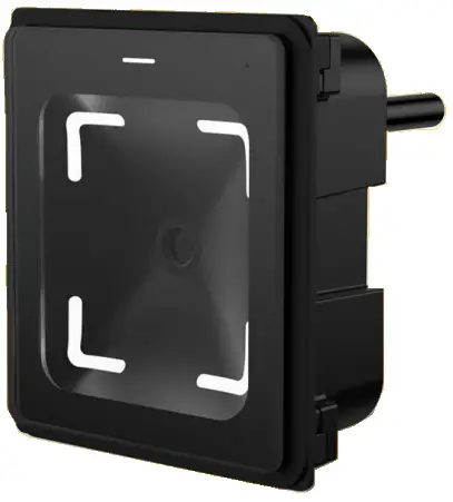
Product appearance
2.1.1. OVERALL INTRODUCTION 2.1.2. PRODUCT SIZE
Product parameters
3.1. General parameters
| General parameters | |
| Output interface | RS485, RS232, TTL, Wiegand, Ethernet |
| Indicating method | Red, green, white light indicator Buzzer |
| Imaging sensor | 300,000 pixel CMOS sensor |
| Max resolution | 640*480 |
| Mounting method | Embedded mounting |
| Size | 75mm*65mm*35.10mm |
3.2. Reading parameter
| QR code recognition parameter | ||
| Symbologies | QR, PDF417, CODE39, CODE93, CODE128, ISBN10, ITF, EAN13, DATABAR, aztec etc. | |
| Supported decoding | Mobile QR code and paper QR code | |
| DOF | 0mm~62.4mm(QRCODE 15mil) | |
| Reading accuracy | ≥8mil | |
| Reading speed | 100ms per time(average), support reading continuously | |
| Reading direction | Ethernet | Tilt ± 62.3 ° Rotation ± 360 ° Deflection ± 65.2 °(15milQR) |
| RS232, RS485, Wiegand, TTL | Tilt ± 52.6 ° Rotation ± 360 ° Deflection ± 48.6 °(15milQR) | |
| FOV | Ethernet | 86.2° (15milQR) |
| RS232, RS485, Wiegand, TTL | 73.5° (15milQR) | |
| RFID reading parameter | ||
| Supported cards | ISO 14443A, ISO 14443B protocol cards, ID card(only physical card number) | |
| Reading method | Read UID, read and write M1 card sector | |
| Working frequency | 13.56MHz | |
| Distance | <5cm | |
3.3. Electric parameters
The power input can be provided only when the device is connected properly. If the device is plugged or unplugged while the cable is live (hot plugging), its electronic components will be damaged. Make sure that the power is turned off when plugging and unplugging the cable.
| Electric parameters | ||
|
Working voltage |
RS232, RS485, Wiegand, TTL | DC 5-15V |
| Ethernet | DC 12-24V | |
|
Working current |
RS232, RS485, Wiegand, TTL | 156.9mA(5V typical value) |
| Ethernet | 92mA(5V typical value) | |
|
Power consumption |
RS232, RS485, Wiegand, TTL | 784.5mW(5V typical value) |
| Ethernet | 1104mW(5V typical value) | |
3.4. Working environment
| Working environment | |
| ESD protection | ±8kV(Air discharge),±4kV(Contact discharge) |
| Working temp | -20°C-70°C |
| Storage temp | -40°C-80°C |
| RH | 5%-95%(No condensation)(environment temperature30℃) |
| Ambient light | 0-80000Lux(Non direct sunlight) |
Interface definition
4.1. RS232, RS485 Version
|
Serial number |
Definition |
Description |
|
| 1 | VCC | Positive power supply | |
| 2 | GND | Negative power supply | |
| 3 | 232RX/485A | 232 Version | Data receiving end of code scanner |
| 485 Version | 485 _A cable | ||
| 4 | 232TX/485B | 232 Version | Data sending end of code scanner |
| 485 Version | 485 _B cable | ||
4.2 .Wiegand&TTL Version
|
Serial number |
Definition |
Description |
|
| 4 | VCC | Positive power supply | |
| 3 | GND | Negative power supply | |
| 2 | TTLTX/D1 | TTL | Data sending end of code scanner |
| Wiegand | Wiegand 1 | ||
| 1 | TTLRX/D0 | TTL | Data receiving end of code scanner |
| Wiegand | Wiegand 0 | ||
4.3 Ethernet Version
|
Serial number |
Definition |
Description |
| 1 | COM | Relay common terminal |
| 2 | NO | Relay normally open end |
| 3 | VCC | Positive power supply |
| 4 | GND | Negative power supply |
| 5 | TX+ | Data transmission positive end (568B network cable pin1 orange and white) |
| 6 | TX- | Data transmission negative end(568B network cable pin2-orange) |
| 7 | RX+ | Data receiving positive end (568B network cable pin3 green and white) |
| 8 | RX- | Data receiving negative end(568B network cable pin6-green) |
4.4. Ethernet+Wiegand Version
 RJ45 port connect to the network cable, 5pin and 4Pin screws interface descriptions are as follows:
5PIN interface
|
Serial number |
Definition |
Description |
| 1 | NC | Normally closed end of relay |
| 2 | COM | Relay common terminal |
| 3 | NO | Relay normally open end |
| 4 | VCC | Positive power supply |
| 5 | GND | Negative power supply |
4PIN interface
|
Serial number |
Definition |
Description |
| 1 | MC | Door magnetic signal input terminal |
| 2 | GND | |
| 3 | D0 | Wiegand 0 |
| 4 | D1 | Wiegand 1 |
Device configuration
Use the Vguang config tool to configure the device.Open the following configuration tools (available from the download center on the official website) 5.1 config tool
Config the device as the step shows, the example are showing 485 version reader.
Step 1, Select the model number Q350 (Select M350 in the configuration tool) .
 Step 2, Select the output interface, and config the corresponding serial parameters.
 Step 3, select the required configuration. For configuration options, please refer to the user manual of Vguangconfig configuration tool on the official website.
  Step 4, After configing as your needs, click “config code”
  Step 5, Use the scanner to scan the configurations QR code generated by the tool, then restart the reader to finish the new configurations.
For more details about configurations, please refer to the “Vguang configuration tool user manual”.
Mounting method
The product using CMOS image sensor, the recognition window should avoid direct sun or other strong light source when install the scanner. The strong light source will cause the contrast in the image too big to decoding, the long term exposure will damage the sensor and cause the device failure.
The recognition window are using tempered glass, which has good transmission of the light, and also a good pressure resistance, but still need to avoid scratching the glass by some hard object, it will affect the QR code recognition performance.
The RFID antenna was in the underside of the recognition window, there should have no metal or magnetic material within 10cm when installing the scanner, or it will affect the card reading performance.
Step 1: Open a hole in the mounting plate.70*60mm
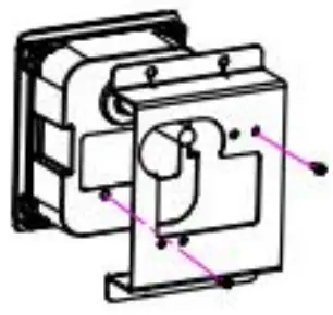
 Step 2: Assemble the reader with the holder, and tighten the screws, then plug the cable.M2.5*5 self tapping screw.
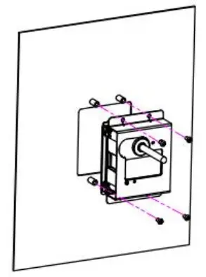
 Step 3: assemble the holder with themounting plate, then tighten the screws.
 Step 4, installation finished.
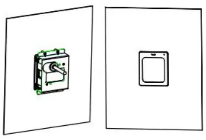
Attention
- The equipment standard is 12-24V power supply, it can get power from the access control power or power it separately. Excessive voltage may cause the device fail to work normally or even damage the device.
- Do not disassemble the scanner without permission, otherwise the device may be damaged.
- 3, The installation position of the scanner should avoid direct sunlight. Otherwise, the scanning effect may be affected. The panel of the scanner must be clean, otherwise it may affect the normal image capture of the scanner. The metal around the scanner may interfere with the NFC magnetic field and affect card reading.
- The wiring connection of the scanner must be firm. In addition, ensure the insulation between the lines to prevent the equipment from being damaged by a short circuit.
Contact info
Company name: Suzhou CoolCode Technology Co., Ltd.
Address: Floor 2, Workshop No. 23, Yangshan Science and Technology Industrial Park, No. 8, Jinyan
Road, High—tech Zone, Suzhou, China
Hot line: 400-810-2019
Warning Statement
FCC Warning:
This device complies with Part 15 of the FCC Rules. Operation is subject to the following two conditions:
- this device may not cause harmful interference, and
- this device must accept any interference received, including interference that may cause undesired operation.
Changes or modifications not expressly approved by the party responsible for compliance could void the user’s authority to operate the equipment.
NOTE: This equipment has been tested and found to comply with the limits for a Class B digital device, pursuant to Part 15 of the FCC Rules. These limits are designed to provide reasonable protection against harmful interference in a residential installation. This equipment generates uses and can radiate radio frequency energy and, if not installed and used in accordance with the instructions, may cause harmful interference to radio communications. However, there is no guarantee that interference will not occur in a particular installation. If this equipment does cause harmful interference to radio or television reception, which can be determined by turning the equipment off and on, the user is encouraged to try to correct the interference by one or more of the following measures:
–Reorient or relocate the receiving antenna.
–Increase the separation between the equipment and receiver.
–Connect the equipment into an outlet on a circuit different from that to which the receiver is connected.
–Consult the dealer or an experienced radio/TV technician for help.
NOTE: This device and its antenna(s) must not be co-located or operation in conjunction with any other antenna or transmitter
RF Exposure Statement
To maintain compliance with FCC’s RF Exposure guidelines, This equipment should be installed and operated with minimum distance of 20cm the radiator your body. This device and its antenna(s) must not be co-located or operation in conjunction with any other antenna or transmitter
ISED Canada Statement:
This device contains licence-exempt tasmittre(s)/receiver(s)/ that comply with Innovation Science and Economic Development Canada ‘s licence-exempt RSS(s).
Operation is subject to the following two conditions:
- this device may not cause interference and
- this device must accept any interference, including interference that may cause undesired operation of the device.
Radiation Exposure: This equipment complies with Canada radiation exposure limits set forth for an uncontrolled environment
RF Exposure Statement
To maintain compliance with IC’s RF Exposure guidelincs, This cquipment should be.installed and operated with minimum distance of 20mm the radiator your body.
This device and its antenna(s) must not be co-located or operation in conjunction with any other antenna or transmitter. ![]()
Documents / Resources
 |
CoolCode Q350 QR Code Access Control Reader [pdf] User Manual Q350 QR Code Access Control Reader, Q350, QR Code Access Control Reader, Code Access Control Reader, Access Control Reader, Control Reader, Reader |