![]()
SIEMENS STRI-M Addressable Interface Module
Installation Instructions Model STRI-M
Addressable Interface Module
The Model STRI-M Series Addressable Interface Module from Siemens Building Technologies, Inc. interfaces direct shorting devices to the FDLC loop circuit of the FS-250C System. The STRI-M can monitor a normally open or closed dry contact and it can report the status of the contact.

PROGRAMMING
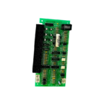
Refer to Figure 1 to locate the red and black FDLC loop circuit wires of the STRI-M. Connect the Addressable Loop Driver circuit wires of the STRI-M to the Model SDPU Programmer/Tester. Use the cable provided with the Programmer/Tester and the 2 alligator clip to banana plug adapters provided.
CAUTION
To Prevent Damage To The SDPU:
DO NOT connect a STRI-M to the SDPU until all field wiring is removed from the red and black FDLC loop circuit wires of the STRI-M. Connection from the SDPU to the STRI-M is not polarity sensitive. Refer to Figure 3 for the proper connections to the control panel. (Refer to Figure 2.) Follow the instructions in the SDPU Programmer/Tester Manual (P/N 315-033260C) to program the desired address into STRI-M. Record the device address on the label located on the STRI-M. The STRI-M can now be installed and wired to the system.

NOTES:
- There can be any number of normally closed or normally open switches.
- The end of line resistor must be located at the last switch.
- Do not wire a normally closed switch across the end of line resistor.
- Only for use with status applications.
Figure 2
Wiring Switches
WIRING
(Refer to Figure 3.) Refer to the wiring diagram and wire the addressable interface module accordingly.
NOTE
Recommended wire size:
- 18 AWG minimum
- 14 AWG maximum

Figure 3
Installing the STRI-M Wiring.
NOTES:
- All supervised switches must be held closed and/or open for at least a quarter of a second to guarantee detection.
- End of line device: 470 ohm, 1/4W resistor, P/N 140-820164. Use Model EL-33 with 470 ohm, 1/4W resistor.
- STRI-M is polarity insensitive. Line 1 and Line 2 can be either line of the loop.
- Addressable Loop Electrical ratings:
Voltage: 24 VDC pulsing, 31 VDC max.
Current maximum: 1.3mA during polling - The supervised switches have the following ratings:
Voltage maximum: 6 VDC
Current maximum: 6mA during polling Contact resistance maximum: 10 ohms.
Maximum cable length: 200 feet (18 AWG)
Max line size: 14 AWG
Min line size: 18 AWG
CAUTION
Ground shield ONLY at the specified location on the Control Panel. EOL device must be a 470 ohm, 1/4 W resistor. When replacing an existing STRI on a device loop, you must also replace the EOL resistor if it is not 470 ohms, 1/4W. - The green wire must be connected to earth ground.
- Use wire nuts to pass the shield wire through the electrical box with NO connection to the device green wire.
- Use shielded wire to connect the switch wiring.
- Tie the switch wiring shield to earth ground.
- In supervisory: STRI-M draws 1.3mA
- All circuits are power limited.
- Positive and negative ground fault detected at <60K ohms for orange terminals.
MOUNTING
The Model STRI-M mounts directly into a single gang switchbox (user supplied). Connect the appropriate wires using wire nuts. Tuck the STRI-M module inside the electrical box and dress the wiring as required. (See Figure 4.).
Siemens Building Technologies, Ltd. 2 Ken view Boulevard
Brampton, Ontario L6T 5E4 Canada.
Documents / Resources
 |
SIEMENS STRI-M Addressable Interface Module [pdf] Instruction Manual STRI-M, STRI-M Addressable Interface Module, Addressable Interface Module, Interface Module, Module |