POWER-POLE view 106874OM Touch Screen Display

Specifications
- Product Name: Power-Pole View
- Control Hub for Power-Pole shallow water anchors, MOVE brushless trolling motor, and CHARGE Marine Power Station
- Ultra-thin touchscreen design for simplicity, precision, and performance
- Comes with a two-year warranty
Product Usage Instructions
Register Your View
- To register your View, locate the serial number on top of the unit in the format XXXX-XXXXX-XX. Register your View on the Power-Pole App or by visiting www.power-pole.com and creating an account. Registering your View will enable easy warranty claims.
Installing The View
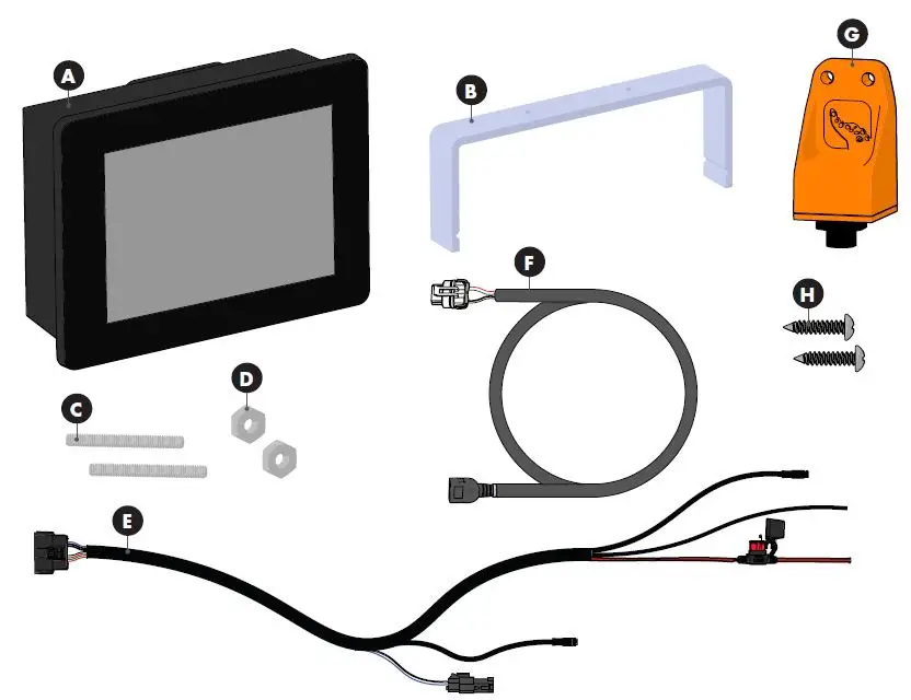
What’s in Your Box
- The Power-Pole View comes with all necessary hardware for installation. Follow the included mounting template to install your View.
Tools Required
- View Mounting Bracket
- #8-32 Stainless Steel Threaded Rod
- #8-32 Stainless Steel Hex Nut
- Wiring Harness
- USB Wire Harness Cable
- C-Monster Gateway
- Mounting Screws
Selecting a Mounting Location
- Determine a suitable mounting location based on the provided parameters. Ensure the area beneath the display is clear of any sensitive components.
Mounting The View
- Before installation, disconnect power by turning off the main battery cutoff switch. Ensure there are no hoses, wires, lines, tanks, or other sensitive components beneath the display area.
REGISTER YOUR VIEW
LOCATE YOUR SERIAL NUMBER
The serial number can be found on top of the unit and is in the format: XXXX-XXXXX-XX
REGISTER THE VIEW
Be sure to register your View on the Power-Pole App or by going to www.power-pole.com and creating an account. Once your view has been registered, our customer service team will be able to easily assist you with any warranty claims.
WARRANTY Information
- To find a Certified Warranty Center, visit www.power-pole.com.
- The VIEW comes with a two year warranty.
Conditions of this Warranty
A VIEW unit by JL Marine Systems, Inc. is warranted against defects in material and workmanship to the original end consumer from the original purchase date according to the following stipulations:
- VIEW warranties are activated when product is registered online at www.power-pole.com/register or by using the Power-Pole App or upon receipt by JL Marine Systems, Inc. of a completed warranty card and dealer receipt/proof of purchase, postdated within (10) days of the original purchase date. Please retain your sales receipt as proof of purchase.
- Install Genuine Power-Pole Merchandise ONLY. This warranty is void if any non-authorized parts are used or installed.
- This warranty is void if the View is used commercially, structurally altered, or subject to stress beyond the physical limits of the manufactured material.
- This warranty does not cover abrasion or abnormal abuse, nor does it cover the Power-Pole VIEW for anything other than its intended use.
- JL Marine Systems, Inc. reserves the right to change products and designs without incurring any obligations to incorporate such changes in already completed products, or those in the hands of dealers or consumers. Products repaired or replaced under this warranty may or may not have these changes.
Shipping (Only applies to packages shipped within the Continental U.S.)
- Parts which prove defective within (90) days from the date of purchase, JL Marine Systems, Inc. will pay for the replacement product shipping and handling fees to and from the JL Marine Systems, Inc. manufacturing plant or some other place which JL Marine Systems, Inc. might designate.
- Parts which prove defective after (90) days but before (12) months from the date of purchase will also be repaired or replaced free of charge, but there may be a shipping charge to JL Marine Systems, Inc. manufacturing plant or some other place which JL Marine Systems, Inc. might designate.
- Parts which prove defective after (12) months will also be repaired or replaced free of charge, but there may be a shipping and handling charge to and from the JL Marine Systems, Inc. manufacturing plant or some other place which JL Marine Systems, Inc. might designate.
THE WARRANTY CONTAINED HEREIN IS THE EXCLUSIVE WARRANTY MADE BY JL Marine Systems, Inc. AND THERE ARE NO OTHER WARRANTIES, EXPRESSED OR IMPLIED, INCLUDING A WARRANTY OF FITNESS FOR A PARTICULAR PURPOSE OR OF MERCHANTABILITY MADE WITH RESPECT TO SUCH DISPLAYS. JL Marine Systems, Inc., IS NOT LIABLE FOR ANY INJURY OR MISHAPS SUSTAINED IN THE USE OF THIS PRODUCT. THE USER OF THIS PRODUCT ACKNOWLEDGES ASSUMED RISKS AND WAIVES ANY AND ALL CLAIMS AGAINST JL Marine Systems, Inc. AND ANY OF IT’S AGENTS.
This warranty applies under conditions of normal use. The warranty does not cover: 1) defects caused by improper assembly or disassembly; 2) defects occurring after purchase due to product modification, intentional damage, accident, misuse, abuse, negligence or exposure to corrosive elements; 3) cosmetic damage and 4) labor or assembly costs. Except as provided herein, JL Marine Systems, Inc. makes no express warranties, and any implied warranty, including without limitation any implied warranty of merchantability or fitness for a particular purpose, is limited in its duration to the duration of the written limited warranty set forth herein. Except as provided herein, JL Marine Systems, Inc. shall have no liability or responsibility to the purchaser or any other person or entity with respect to any liability, loss or damage caused or alleged to be caused directly or indirectly by use of the product, including, but not limited to, any incidental or consequential damages. Some states do not allow limitation on how long an implied warranty lasts or the exclusion of limitation of incidental or consequential damages, so the above limitation and exclusion may not apply to you. This warranty gives you specific legal rights. You may also have other rights which vary from state to state.
SUBMITTING A WARRANTY CLAIM
If you experience issues with your View, you can file a warranty claim by calling our customer service team at +1(813) 689-9932 option 2. For the best service, have your View serial number ready for a customer service representative.
INSTALLING The View
“WHAT’S IN YOUR BOX? The Power-Pole View comes with all the necessary hardware to be installed directly out of the box. Follow these instructions and the included mounting template to install your new View.”

TOOLS
- Mounting Template
- 11/32″ Wrench
- Jig Saw
- Electric Drill
- 1/4″ Drill Bit
- Heat Gun
- Wire Crimper
- 7/64″ Drill Bit
MOUNTING
SELECTING A MOUNTING LOCATION
Read through the requirements below, then follow the instructions contained in the “MOUNTING THE VIEW” section below. Use the following parameters to locate a suitable mounting location:
- Locate a flat surface with adequate space for mounting the display.
- Ensure there are no obstructions or sensitive components on or under the surface where the mounting hardware will be installed.
MOUNTING THE VIEW
 Always disconnect power by turning the main battery cutoff switch to the off position before performing any installations.
 Check the area beneath where the display will be installed to ensure there are no hoses, wires, lines, tanks or other sensitive components
CUT HOLE FOR FLUSH MOUNT
After reading the SELECTING A MOUNTING LOCATION (above), use the included mounting template to locate a suitable location for installing the display. Use the mounting template and included instructions to cut a hole for flush mounting the display.
INSTALL DISPLAY
STEP 1
Install the (2) Threaded Rods C into the Threaded Cavities on the back of the View A and hand tighten until snug.

STEP 2
Install the View A into the previously cut hole so that it is flush with the mounting surface. Install the Mounting Bracket B over the (2) Threaded Rods C so that the mounting surface is sandwiched between the display’s bezel and Mounting Bracket.

STEP 3
Install a Hex Nut D onto each Threaded Rod C. Using an 11/32″ Wrench tighten each nut snug.

INSTALLING THE C-MONSTER GATEWAY
SELECT A MOUNTING LOCATION
Use the following parameters to locate a suitable mounting location:
- Locate a flat surface with adequate space for mounting the Gateway.
- For best performance do not mount on a metal surface or within 6″ of large metal objects.
- Ensure there are no obstructions or sensitive components on or under the boat deck where the mounting hardware will be installed.
- Make sure the mounting location is close enough to reach the NMEA connector on the Wiring Harness E. You may also buy an extension cable to reach the harness if necessary.

INSTALLING THE GATEWAY
STEP 1
- Mark mounting holes for Screws H.
STEP 2
- Drill Mounting Holes using a 7/64” Drill Bit.
STEP 3
- Line Gateway G up with Mounting Holes and install (2) Screws H using a Phillips-Head Screwdriver.
STEP 4
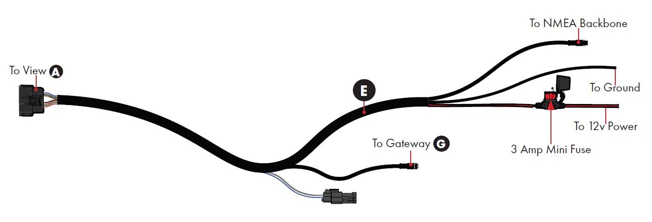
- Screw the Gateway G into male NMEA connector from the Wiring Harness E.
CONNECTING THE VIEW
CONNECT TO EXISTING NMEA BACKBONE
If you have devices for measuring water temperature and/or speed connected to your NMEA backbone, the Total Boat Control Display has the ability to show water temperature and speed. Install the female NMEA connector from the into Wiring Harness E NMEA backbone.
IMPORTANT CONNECTION INFORMATION
For safety and compliance reasons, we recommend that you follow American Boat and Yacht Council (ABYC) standards when wiring your boat. These instructions are meant to serve as a general guide for connecting your display to power. If you have questions, contact our Customer Service Team at +1(813) 689-9932 option 2 or visit our website at www.power-pole.com.
Never connect the positive (+, POS) and negative (-, NEG) terminals of the same battery together. Take care that no metal object falls onto the battery and shorts the terminals. It might spark or short-circuit battery or other electrical component that may cause explosion.
- Always make sure power is shut off to the wires you are working with. NEVER attempt to attach a ring terminal or butt connector to a live wire.
- Disconnect the display from the battery or batteries when not in use.
- Always make sure leadwire connections are tight and secure to battery terminals.
- Make sure batteries are in a well-ventilated compartment.
IMPORTANT! The positive and negative leads may be extended, but must be done within ABYC rigging standards.
STEP 1
- Strip back the insulation on the wire(s) from Wiring Harness E so around 1/4″ of wire is exposed.
STEP 2
- Twist the exposed wire ends and insert them into the Butt Connector or Ring Terminal.
IMPORTANT! Ensure no uninsulated wire is exposed past the end of the Heat Shrink.
STEP 3
- Crimp the Ring Terminals onto the wire using the Crimping Tool.

IMPORTANT! Check Ring Terminal or Butt Connector for any cuts from crimping and give the cables a slight tug to ensure they are properly crimped. Poorly crimped or damaged connectors will not provide a water-tight seal. This will lead to corrosion and wire failure.
STEP 4
- Use a Heat Gun to “shrink” the Heat Shrink of the Ring Terminals to the wire. Ensure no bubbles are present and the jacket has shrunk tightly to the insulation on the wire.
STEP 5
- Plug the Wiring Harness E into the back of the View A.
STEP 6
- Route to power.

IMPORTANT! The unit does not have an on/off switch, so as it will turn on as soon as it is connected to power and will remain on until disconnected.
OPERATING the VIEW
PAIRING DEVICES
Any Power-Pole products (Anchors, Move, etc.) must be paired to the Gateway in order to sync to the View. The instructions below detail how to open the pairing window and pair all compatible products. Once Paired, the respective ribbon icon color will change from gray ![]() to black
to black ![]() .
.
OPEN GATEWAY PAIRING WINDOW
Tap the![]() icon in the bottom right corner to access the settings page. From there, you may access the system, configuration, and diagnostics pages.
icon in the bottom right corner to access the settings page. From there, you may access the system, configuration, and diagnostics pages.

PAIRING THE MOVE
- Hold the Move Remote within 3 ft. of the Move and tap
 and
and  at the same time.
PAIRING THE CHARGE
- Press and release the C-Monster
 button.
PAIRING POWER POLE ANCHORS
- Hold the C-Monster button on the HPU for 3 seconds (until the pump beeps). This will need to be done for each pump.
NOTICE: Currently, only One Pump models can be paired to two or more Gateways. If there is a Gateway already installed on your NMEA backbone, remove it and install it into the Wiring Harness E. Install the included Gateway into your NMEA backbone and pair any other devices.
SCREEN OVERVIEWS
SCREEN OVERVIEWS
The following section will explain the functionality of the View. Depending on what Power-Pole products you have installed on your vessel, your screen may look differently than the ones pictured below. Any paired Power-Pole products will populate on the overview ribbon. To navigate between overview pages, tap the desired page on the overview ribbon.
HOME SCREEN

*If low voltage, numbers will display red.
ANCHORS PAGE

*Power-Pole One Pump Systems will only offer dual control
CHARGE PAGE

ICON KEY

MOVE PAGE


FEATURES OVERVIEW
SETTINGS
- Tap the
 icon in the bottom right corner to access the settings page. From there, you may access the system, configuration, and diagnostics pages.
PERFORMING AN UPDATE

CHANGING BRIGHTNESS SETTINGS

PERFORMING A FACTORY RESET

CHANGE UNITS OF MEASUREMENT

VIEW DIAGNOSTICS

FCC STATEMENTS
General Statement (for all devices)
Warning: Changes or modifications to this device not expressly approved by JL Marine Systems, Inc. could void the user’s authority to operate the equipment.
FCC Specific Statement
NOTE: This equipment has been tested and found to comply with the limits for a Class B digital device, pursuant to Part 15 of the FCC Rules. These limits are designed to provide reasonable protection against harmful interference in a residential installation. This equipment generates, uses, and can radiate radio frequency energy and, if not installed and used in accordance with the instructions, may cause harmful interference to radio communications. However, there is no guarantee that interference will not occur in a particular installation. If this equipment does cause harmful interference to radio or television reception, which can be determined by turning the equipment off and on, the user is encouraged to try to correct the interference by one or more of the following measures:
- Reorient or relocate the receiving antenna.
- Increase the separation between the equipment and receiver
- Connect the equipment into an outlet on a circuit different from that to which the receiver is connected
- Consult the dealer or an experienced radio/TV technician for help
FCC Part 15.19 Warning Statement
(Required for all Part 15 devices) THIS DEVICE COMPLIES WITH PART 15 OF THE FCC RULES. OPERATION IS SUBJECT TO THE FOLLOWING TWO CONDITIONS: (1) THIS DEVICE MAY NOT CAUSE HARMFUL INTERFERENCE, AND (2) THIS DEVICE MUST NOT ACCEPT ANY INTERFERENCE RECEIVED, INCLUDING INTERFERENCE THAT MAY CAUSE UNDESIRED OPERATION.
FCC Part 15.21 Warning Statement
NOTE: THE GRANTEE IS NOT RESPONSIBLE FOR ANY CHANGES OR MODIFICATIONS NOT EXPRESSLY APPROVED BY THE PARTY RESPONSIBLE FOR COMPLIANCE. SUCH MODIFICATIONS COULD VOID THE USER’S AUTHORITY TO OPERATE THE EQUIPMENT.
FCC/ISED RF Exposure
This equipment complies with radiation exposure limits set forth for an uncontrolled environment. This equipment is in direct contact with the body of the user under normal operating conditions. The transmitter must not be co-located or operating in conjunction with any other antenna or transmitter.
This device complies with Industry Canada license-exempt RSS standard(s). Operation is subject to the following two conditions: (1) this device may not cause interference, and (2) this device must not accept any interference, including interference that may cause undesired operation of the device.
Contact
Need help? Contact our Customer Service Team at +1813.689.9932 option 2
9010 Palm River Road, Tampa, Florida 33619
- Phone: 1+813-689-9932
- Fax: 1+813-689-8883
- www.power-pole.com
FAQs
What size fuse is used?
The View uses a 3 Amp bladed fuse.
What is the length of the Wire Harness?
40
Will I need to use an additional C Monster Gateway?
Depending on your intended use for the View you may need to use two C Monster Gateways. One is for the View to communicate with our other products Move Charge and Anchors. The other C Monster Gateway is on the NMEA Network to provide data MFD s that work with our products.
Does it have an On Off Button?
No It should be wired to a switch. A Key On switch separate switch or main breaker would all be acceptable options.
Can the View be mounted in portrait?

No it is only designed to run in landscape mode.
How do I submit a warranty claim?
If you experience issues with your View call customer service at +1813 689 9932 option 2 and have your View serial number ready for assistance.
Documents / Resources
 |
POWER-POLE view 106874OM Touch Screen Display [pdf] Installation Guide 106874OM, view 106874OM Touch Screen Display, view 106874OM, Touch Screen Display, Screen Display, Display |