![]()
RAYCHEM
NGC-40-PTM Power and Termination Module
Instruction Manual
NGC-40-PTM
Power and Termination Module for use with nVent RAYCHEM NGC-40 system
Installation Instructions
DESCRIPTION
The invent RAYCHEM NGC-40-PTM accepts a primary and redundant power supply input, accepts CAN bus inputs, and provides for termination of the CAN bus. The NGC-40-PTM then distributes both power and Can bus signals to other NGC-40 modules. Each NGC-40-PTM can provide power for a maximum of 10 NGC-40 modules.
TOOLS REQUIRED
• Small flat-blade screwdriver
ADDITIONAL MATERIALS
- Custom built CAN cables with RJ-45 connections
- CAN Termination Resistor
KIT CONTENTS
| Item | Qty | Description |
| A | 1 | NGC-40-PTM module |
APPROVALS AND CERTIFICATIONS
Hazardous Locations
![]() Class I, Div. 2, Groups A,B,C,D T4
Class I, Div. 2, Groups A,B,C,D T4
Class I, Zone 2, Apex nab IIC T4 IP20
Ex nab IIC T4 X
–40˚C ≤ Ta ≤ +65˚C
Conforms to:![]()
FM Class Number 3600 (11/98)
FM Class Number 3611 (10/99)
ANSI/UL STD. 60079-15-2009
UL STD. 61010-1
Certified to:
CAN/CSA STD. C22.2 No. 213-M1987 (R2004)
CAN/CSA STD. C22.2 No. 61010-1:2004
EN 61010-1 (2001)
CAN/CSA STD. E60079-15:02 (R2006)
IEC Ex Markings:
IECEx ETL 17.0062x
EX ed IIC T4 Go
ATEX Markings:
ITS17ATEX402833X
![]() II 3 G Ex ed IIC T4 Go
II 3 G Ex ed IIC T4 Go
Special conditions of use for IEC Ex and ATEX :
- The overall equipment is evaluated to type of protection “ed”.
- For full connection details see these installation instructions.
- The equipment shall only be used in an area of not more than pollution degree 2, as defined in IEC/EN 60664-1.
- The equipment shall be installed in an enclosure that provides a minimum ingress protection of IP54 in accordance with IEC/EN 60079-0.
- Transient protection shall be provided which is set at a level not exceeding 140% of the peak rated voltage value at the supply terminals to the equipment.
![]() WARNUNG:
WARNUNG:
This component is an electrical device that must be installed correctly to ensure proper operation and to prevent shock or fire.
For technical support, call invent at 800-545-6258.
GENERAL
| Supply voltage | 24 Vdc ± 10% |
| Internal power consumption | 1 W per NGC-40-PTM |
| Output current | 1.5 Amps @ 24 V |
| Ambient operating temperature | –40ºC to 65ºC (–40ºF to 149ºF) |
| Ambient storage temperature | –55ºC to 75ºC (–67ºF to 167ºF) |
| Environment | PD2, CAT III |
| Max. altitude | 2,000 m (6,562 ft) |
| Humidity | 5 – 90% noncondensing |
| Mounting | Din Rail – 35 mm |
ELECTROMAGNETIC COMPATIBILITY
| Emissions | EN 61000-6-3 Emission standard for residential, commercial and light industrial environments |
| Immunity | EN 61000-6-2 Immunity standard for industrial environments |
CAN NETWORKING PORT
| Type | 2-wire isolated CAN-based peer-peer network. Isolated to 300 V. |
| Connection | Two 8-pin RJ-45 connectors (both may be used for Input or Output connections) |
| Topology | Daisy chain |
| Length | 10 m (33 ft) maximum |
| Quantity | Up to 10 CAN nodes per PTM module |
CONNECTION TERMINALS
| Wiring terminals | Cage clamp, 0.5 to 2.5 mm2 (24 to 18 AWG). |
| As the current to the modules require up to 2.05 A @ 24Vdc (20 modules–see CAN Bus connection diagrams) the minimum wire size to the module shall be 1.0 mm2 (AWG18) | |
| CAN networking and module power | Two RJ-45 connectors, one each IN and OUT. Provides CAN bus signals and 24 Vdc power. |
HOUSING
| Size | 45.1 mm (1.78 in) wide x 87 mm (3.43 in) high x 106.4 mm (4.2 in) deep |
SYSTEM POWER SUPPLY REQUIREMENTS
| Output voltage | 24 Vdc ±10% |
| Approval | NRTL approved device for use in nonhazardous or hazardous locations as appropriate |
| Overcurrent protection | Must have an automatic disconnect upon a single fault condition |
System Components

A. WIRING TERMINALS
| TERMINALS | FUNCTION |
| 1 | Primary 24 Vdc In (+) |
| 2 | Primary 24 Vdc In (–) |
| 3 | Primary 24 Vdc Out (+) |
| 4 | Primary 24 Vdc Out (–) |
| 5 | Redundant 24 Vdc In (+) |
| 6 | Redundant 24 Vdc In (–) |
| 7 | Redundant 24 Vdc Out (+) |
| 8 | Redundant 24 Vdc Out (–) |
B. STATUS LEDS
STATUS:
24 Vdc Primary
Off No power
Green Power on
24 Vdc Redundant
Off No power
Green Power on
C. CAN / TERM
D. CAN / 24 VDC
Mounting the NGC-40-PTM
Each NGC-40-PTM mounts on a DIN 35 rail.
MOUNTING: Insert the rear bottom of the module into the DIN rail, then push up and inwards to engage the clip.
REMOVAL: Push the module upwards to disengage the clip, then rotate the module toward you.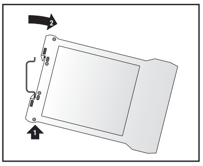
24 Vdc Connection (In)
Note: Power supply should have a means for disconnect from line voltage.
Note: Assemble, lock and mount power supply per manufacturer’s instructions.
24 Vdc Connection (Out)

Note: The primary and redundant 24 Vdc outputs each support only one additional NGC-40 PTM module
CAN Networking Port
The CAN termination device must be installed in the unused port of the last module.
Provide Suitable Panel Enclosure and Determine Locations for NGC-40-PTM Assembly in Panel
- Provide suitable panel enclosure
The NGC-40-PTM must be mounted in an enclosure to protect its electronic components. For indoor applications, use a minimum NEMA 1 enclosure (NEMA 12 recommended). For outdoor applications, use a NEMA 4 or NEMA 4X enclosure depending on the requirements.
Note: The NGC-40-PTM is designed for operation in ambient temperatures from –40°C to 65°C (–40°F to 149°F). If the ambient temperature is outside this range, a space heater and/or cooling fan will be required in the panel. - Determine locations for the NGC-40-PTM assembly in the electrical panel.
The NGC-40-PTM should be located in the rear of the panel. The NGC-40PTM assembly is an electronic unit and must not be located where it will be exposed to strong magnetic fields or excessive vibration.

Alarm Relay
The NGC-40-PTM contains no user serviceable parts. Contact your invent representative for service and an RMA number if required.
WARNING–EXPLOSION HAZARD–SUBSTITUTION OF COMPONENTS MAY IMPAIR SUITABILITY FOR CLASS I, DIVISION 2 HAZARDOUS AND NONHAZARDOUS LOCATIONS WARNING–EXPLOSION HAZARD–DO NOT REPLACE NGC-40-PTM UNLESS POWER HAS BEEN SWITCHED OFF OR THE AREA IS KNOWN TO BE NONHAZARDOUS WARNING–EXPLOSION HAZARD–DO NOT DISCONNECT EQUIPMENT UNLESS POWER HAS BEEN SWITCHED OFF OR THE AREA IS KNOWN TO BE NONHAZARDOUS
NGC-40 CAN Bus Connections for Up to 10 Modules

NGC-40 CAN Bus Connections for Up to 20 Modules
NGC-40 CAN Bus Connections for Up to 40 Modules

| North America Tel +1.800.545.6258 Fax +1.800.527.5703 thermal.info@nVent.com |
Europe, Middle East, Africa Tel +32.16.213.511 Fax +32.16.213.604 thermal.info@nVent.com |
Asia Pacific Tel +86.21.2412.1688 Fax +86.21.5426.3167 cn.thermal.info@nVent.com |
Latin America Tel +1.713.868.4800 Fax +1.713.868.2333 thermal.info@nVent.com |
![]()
©2022 invent. All invent marks and logos are owned or licensed by
invent Services GmbH or its affiliates.
All other trademarks are the property of their respective owners.
invent reserves the right to change specifications without notice.
RAYCHEM-IM-H58119-NGC40PTM-EN-2202
nVent.com/RAYCHEM
Documents / Resources
 |
nVent RAYCHEM NGC-40-PTM Power and Termination Module [pdf] Instruction Manual NGC-40-PTM Power and Termination Module, NGC-40-PTM, Power and Termination Module, Termination Module, Module |