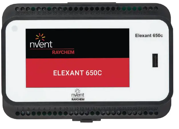
nVent RAYCHEM Elexant 650c-Modbus Protocol Interface Mapping

Product Specifications
- Modbus Protocol Interface
- Modbus RTU via RS485
- Variable Address Range: 1 to 247
- Baud Rate Options: 2400, 4800, 9600, 19200
- Parity Options: None, Odd, Even
- Stop Bits Options: 1, 2
Product Usage Instructions
Introduction
The product uses the Modbus protocol for communication. The manual provides details about the system’s configuration, resources, setup parameters, current conditions, alarms, and other data points.
How to Use This Manual
The manual includes the complete Modbus register map. It is recommended that system integrators thoroughly test their system after writing to the database to ensure proper functionality.
Frequently Asked Questions (FAQ)
Q: What is the default Modbus Station Address?
A: The default Modbus Station Address used to identify the controller is 1.
INTRODUCTION
This manual details the Modbus registers of the nVent RAYCHEM Elexant 650c – Modbus. It is intended to be used by the users’ system integrators who wish to interface with their external device (i.e. DCS or Building management system – BMS – system)
to the using the Modbus protocol. The manual includes details of the system’s current configuration, availability resources, set-up parameters, current conditions, alarm status, log info and numerous other fixed and variable data points.
How to Use This Manual
The Elexant 650c – Modbus register can be accessed by DCS or BMS systems. However, this should only be done by expert users who understand that the system makes use of extensive semaphore fields to assure synchronization between the possibility of multiple users and conflicting instructions. These portions of the Modbus register map provide access to the current set – up and real time values being measured by the system. A snap shot of the current conditions, data for trending, alarm status, the current setting for the alarm thresholds and setpoints can be easily read without any risk to the system performance.
The entire Modbus register map is included in this document for completeness. Writing to the database is within the capability of most Modbus host devices. However, we strongly recommend that system integrators who write to the database must thoroughly test their system to ensure it is working properly and that there are no unintended consequences.
Modbus Communications
The controller acts as Modbus slave device. A modbus master device can read and write to the controller. This enables the possibility to monitor, configure and view the alarms remotely. The protocol used is Modbus RTU via RS485.
| Variable | Description | Default | Range/options |
| Address | Modbus Station Address used to identify the controller. | 1 | 1 to 247 |
| Baud | The data rate at which communications occur on the serial network. | 9600 | 2400, 4800, 9600, 19200 |
| Parity | Parity Defines the type of parity bit to be used with any of the three serial communications ports. | None | None, Odd, Even |
| Stop Bits | Defines the number of stop bits used with any of the three serial communications ports. | 1 | 1,2 |
The host defaults are:
- Modbus Address: 1
- Baud Rate: 9600
The standard configuration is: 8 data bits, no parity and one stop bit.
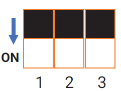
The dip switches (below terminal 26 and 27):
| Button | Resistor |
| 1 | Pull down resistor |
| 2 | Pull up resistor |
| 3 | Termination resistor |

Push the button to ON (as the arrow indicates) side will connect the corresponding resistor in.
MODBUS REGISTER MAP
Alarm Status Coils
- Modbus Function Code: 1
- Modbus Start Address: 4
- Modbus Block Size: 13
- Number of Blocks: 1
| Description | Modbus Address | Function | Comments |
| TS 1 Failure | 4 | 1 | 0 = no alarm, 1 = alarm |
| TS 2 Failure | 5 | 1 | 0 = no alarm, 1 = alarm |
| Internal Error | 15 | 1 | 0 = no internal error, 1 = internal error |
| Panel Alarm status | 16 | 1 | 0 = no alarm, 1 = alarm |
Controller Setup Parameters
- Modbus Function Code: 1, 5, 15
- Modbus Start Address: 145
- Modbus Block Size: 5
- Number of Blocks: 1
| Description | Modbus Address | Function | Comments |
| TS1 Fail Mode | 145 | 1, 5, 15 | 0 = Fail off, 1 = Fail on |
| TS2 Fail Mode | 146 | 1, 5, 15 | 0 = Fail off, 1 = Fail on |
| Test Program | 147 | 1, 5, 15 | 0 = no, 1 = yes, test program is running |
| Alarm Buzzer | 148 | 1, 5, 15 | 0 = no, buzzer off 1 = yes, buzzer on |
| Panel Alarm Control | 149 | 1, 5, 15 | 0 = alarm deactive, 1 = alarm active |
Controller Status
- Modbus Function Code: 2
- Modbus Start Address: 3
- Modbus Block Size: 3
- Number of Blocks: 1
| Description | Modbus Address | Function | Comments |
| Raw Switch Output1 | 3 | 2 | 0 = HC1 relay off, 1 = HC1 relay on |
| Keylock Status | 4 | 2 | 0 = no, 1 = yes, locked |
| Raw Switch Output2 | 5 | 2 | 0 = HC2 relay off, 1 = HC2 relay on |
INPUT Parameters
- Modbus Function Code: 3, 6, 16
- Modbus Start Address: 0
- Modbus Block Size: 19
- Number of Blocks: 1
| Description | Modbus Address | Function | Comments | Units | Scaling |
| Control Moisture Setpoint 1 | 0 | 3, 6, 16 | 1–10 | – | 1 |
| Switch Control Mode | 2 | 3, 6, 16 | 4 = Line/Line, 5 = ECO1/ECO1,
6 = Line/ECO1, 7 = ECO1/Line, 8 = Line/OFF, 9 = ECO1/OFF, 10 = OFF/Line, 11 = OFF/ECO1, 12 = OFF/OFF, 13 = Line/ECO2, 14 = ECO1/ECO2, 15 = ECO2/ECO2, 16 = OFF/ECO2, 17 = ECO2/OFF, 18 = ECO2/Line, 19 = ECO2/ECO1 |
– |
1 |
|
Sensor Setup |
7 | 3, 6, 16 | bit 1 = TS 1 assign for Circuit 1
bit 2 = TS 2 assign for Circuit 1 bit 5 = TS 1 assign for Circuit 2 bit 6 = TS 2 assign for Circuit 2 bit 0,3,4,7 = NA 0 = No (No select) 1 = Yes (Select) |
– |
1 |
| Language | 8 | 3, 6, 16 | 0 = DANISH, 1 = GERMAN,
2 = DUTCH, 3 = ENGLISH, 4 = FRENCH, 5 = ITALIAN, 6 = SWEDISH, 7 = NORWEGIAN, 8 = FINNISH, 9 = RUSSIAN, 10 = CZECH, 11 = POLISH, 12 = JAPANESE, 13 = MANDARIN, 14 = LITHUANIAN |
– |
1 |
| Country | 9 | 3, 6, 16 | 0 = GERMANY, 1 = AUSTRIA,
2 = SWITZERLAND, 3 = UK, 4 = FRANCE, 5 = ITALY, 6 = POLAND, 7 = CZECH REPUBLIC, 8 = DENMARK, 9 = BELGIUM, 10 = RUSSIA, 11 = CHINA, 12 = JAPAN, 13 = SWEDEN, 14 = NORWAY, 15 = LITHUANIA, 16 = SLOVAKIA, 17 = NETHERLANDS, 18 = FINLAND, 19 = IRELAND |
– |
1 |
| Cable type 1 | 10 | 3, 6, 16 | 0 = CABLE_GM2CW, 1 = CABLE_EMMI,
2 = CABLE_ICESTOPGM2X, 3 = CABLE_EMEM2XR, 4 = CABLE_FROSTSTOP_BLACK, 5 = CABLE_WINTER_GARD, 6 = CABLE_WINTERGARD_MAT |
– |
1 |
| Cable type 2 | 11 | 3, 6, 16 | 0 = CABLE_GM2CW, 1 = CABLE_EMMI,
2 = CABLE_ICESTOPGM2X, 3 = CABLE_EMEM2XR, 4 = CABLE_FROSTSTOP_BLACK, 5 = CABLE_WINTER_GARD, 6 = CABLE_WINTERGARD_MAT |
– |
1 |
| Date – Year | 13 | 3, 6, 16 | 18 – 99 | year | 1 |
| Date – Month | 14 | 3, 6, 16 | 1 – 12 | month | 1 |
| Date – Day | 15 | 3, 6, 16 | 1 – 31 | day | 1 |
| Time – Hour | 16 | 3, 6, 16 | 0 – 23 | hour | 1 |
| Time – Minute | 17 | 3, 6, 16 | 0 – 59 | minute | 1 |
| Control Moisture Setpoint 2 | 18 | 3, 6, 16 | 1 – 10 | – | 1 |
Temperature Sensor Parameters
- Modbus Function Code: 3, 6, 16
- Modbus Start Address: 20
- Modbus Block Size: 4
- Number of Blocks: 1
| Description | Modbus Address | Function | Comments | Units | Scaling |
| TS 1 Upper Limit | 20 | 3, 6, 16 | 0°C – 5°C | °C | 10ths* |
| TS1 Lower Limit | 21 | 3, 6, 16 | –31°C – 5°C –31°C = Off | °C | 10ths* |
| TS 2 Upper Limit | 22 | 3, 6, 16 | 0°C – 5°C | °C | 10ths* |
| TS 2 Lower Limit | 23 | 3, 6, 16 | –31°C – 5°C –31°C = Off | °C | 10ths* |
* Temperature displayed in 1/10th of °C (example: 10°C = 100)
Override
- Modbus Function Code: 3, 6, 16
- Modbus Start Address: 34
- Modbus Block Size: 2
- Number of Blocks: 1
| Description | Modbus Address | Function | Comments | Units | Scaling |
| Remote Override Status 1 | 4 | 6, 16 | 0 = Override not active
1 = Force on Override active 2 = Force off Override active |
– |
– |
| Remote Override Status 2 | 35 | 3, 6, 16 | 0 = Override not active
1 = Force on Override active 2 = Force off Override active |
– |
– |
Output Delay
- Description: Output Delay
- Modbus Address: 40
- Function: 3, 6, 16
- Comments: 0 to 60
- Units: sec
- Scaling: 1
Ice Rain Feature & Sensor Types
| Description | Modbus Address | Function | Comments | Units | Scaling |
| Global Ice Rain Enable | 60 | 3, 6, 16 | 0 = disabled, 1 = enabled | – | – |
| Fallback Setpoint | 61 | 3, 6, 16 | –5°C to 5°C | °C | 10ths |
| Gradient Setpoint | 62 | 3, 6, 16 | 0.5 K to 4 K | K | 10ths |
| 18h Ground Setpoint | 63 | 3, 6, 16 | –15°C to –1°C | °C | 10ths |
| Sensor Typ 1 | 64 | 3, 6, 16 | 0 = UNKNOWN, 1 = ROOF, 2 = RAMP | – | 1 |
| Sensor Typ 2 | 65 | 3, 6, 16 | 0 = UNKNOWN, 1 = ROOF, 2 = RAMP | – | 1 |
Controller’s Identification Tag
- Modbus Function Code: 3, 6, 16
- Modbus Start Address: 90
- Modbus Block Size: 10
- Number of Blocks: 1
| Description | Modbus Address | Function | Comments | Units | Scaling |
| Controller’s Identification Tag | 90 to 99 | , 6, 16 | Letters (A – Z) numbers (0–9), /.()_ – # Two characters per address.
String terminators = Null or space Note: LSByte of 99 is always Null. Input the ascii code for the characters above, for example, input 0 x 4142 (Hex or 16706 in Dec) for register 90, and 0x3031 (in Hex or 12337 in Dec) for register 91, then the controller ID will be AB01. |
– | – |
Console Parameters
- Modbus Function Code: 3, 6, 16
- Modbus Start Address: 120
- Modbus Block Size: 2
- Number of Blocks: 1
| Description | Modbus Address | Function | Comments | Units | Scaling |
| Keylock Passcode | 120 | 3, 6, 16 | 1 to 9999:
Incorrect passcode input will be ignored, and correct input will be valid for 2 minutes. (used to enter the code to unlock access to register 121) |
– |
– |
| Lock Enable/Disable | 121 | 3, 6, 16 | 0 = Keylock inactive,
1 = Keylock active |
– | – |
Communication Parameters
- Modbus Function Code: 3, 6, 16
- Modbus Start Address: 147
- Modbus Block Size: 1
- Number of Blocks: 1
| Description | Modbus Address | Function | Comments | Units | Scaling |
| Communications Activity Time – out | 147 | 3, 6, 16 | Used for load shedding and remote override 0–255 | sec | 1 |
General Controller Information
- Modbus Function Code: 4
- Modbus Start Address: 0
- Modbus Block Size: 4
- Number of Blocks: 1
| Description | Modbus Address | Function | Comments | Units | Scaling |
| Device Type | 0 | 4 | Fixed value = 650 | – | 1 |
| Firmware Version | 1 | 4 | Firmware Version – Major 0–255 | – | 1 |
| Firmware Version | 2 | 4 | Firmware Version – Minor 0–255 | – | 1 |
| Firmware Version | 3 | 4 | Firmware Version – Build 0–255 | – | 1 |
Dynamic Output Status
- Modbus Function Code: 4
- Modbus Start Address: 50
- Modbus Block Size: 9
- Number of Blocks: 1
| Description | Modbus Address | Function | Comments | Units | Scaling |
| Control Output Duty Cycle 1 | 50 | 4 | For Line, ECO1 and ECO2 mode.
100 = full on, 70 = ECO2 mode or ECO1 mode and matching temp. |
% | 1 |
| Tracing Control Status | 51 | 4 | 2 digits, the first for circuit 1 and the second for circuit 2 (for example 0 means both are normal, 12 means circuit 1 = force off, circuit 2 = test program)
0 = normal temperature control 1 = output override force off 2 = Test program in progress 5 = output override force on |
– | 1 |
| Control Output Duty Cycle 2 | 8 | 4 | For Line, ECO1 and ECO2 mode.
100 = full on, 70 = ECO2 mode or ECO1 mode and matching temp. |
% | 1 |
Analog Readings
- Modbus Function Code: 4
- Modbus Start Address: 81
- Modbus Block Size: 4
- Number of Blocks: 1
| Description | Modbus Address | Function | Comments | Units | Scaling |
| Current TS 1
Temperature |
81 |
4 |
TS 1 failure = +3000.0°C TS 1 not used = +3200.0°C |
°C |
10ths* |
| Current TS 2
Temperature |
82 |
4 |
TS 2 failure = +3000.0°C TS 2 not used = +3200.0°C |
°C |
10ths* |
| Last TS1 Moisture Value | 83 | 4 | 3001 = Invalid/Off, Valid Range 0…10 | – | 1 |
| Last TS2 Moisture Value | 84 | 4 | 3001 = Invalid/Off, Valid Range 0…10 | – | 1 |
* Temperature displayed in 1/10th of °C (example: 10°C = 100)
Disclaimer
MODBUS map information is proprietary and confidential. Use of this information is permitted solely in order to implement a communications link between customer equipment and nVent RAYCHEM controllers. It may not be used for any other purpose, and it is not to be disclosed to 3rd parties without the written consent of nVent Thermal LLC.
België/Belgique
Tel +32.16.21.35.02 Fax +32.16.21.36.04 salesbelux@nVent.com
Documents / Resources
 |
nVent RAYCHEM Elexant 650c-Modbus Protocol Interface Mapping Unit [pdf] User Manual E650C-G, Elexant 650c-Modbus Protocol Interface Mapping Unit, Elexant 650c-Modbus, Protocol Interface Mapping Unit, Interface Mapping Unit, Mapping Unit, Unit |


