![]()
USER GUIDE
ROLLER SHUTTER RELAY SWITCH
| Reference: SIN-2-RS-01 Power supply: 230V AC ~ 50Hz Switching capabilities: 230V AC – 3A Consumption: <1W Maximum motor power: 280W Max – 60 Nm Max List of compatible motors available on nodon.fr/loads Radiofrequency range: 868.0 to 868.6 Mhz RF power Max: +3dBm |
Range: up to 30m indoor Operational temperature: -10°C to 40°C Protection rating: IP 30 Pairing: up to 22 controllers EEP (EnOcean Profile): D2-05-00 Dimension: 40 mm (l) x 44 mm (L) x 16,9 mm (h) Weight: 34 g Warranty: 2 years |
INSTALLATION
 Thanks to its compact size, the Roller Shutter Relay Switch can be installed in a connecting box or behind the wall switch which controls the roller shutter or motorized awning.
![]() TIP
TIP
Add the Roller Shutter Relay Switch to the electric panel with NodOn DIN Rail Box*.
* Optional accessory
RELAY SWITCH INPUT/OUTPUT
| N | Terminal for the Neutral |
| L | Terminal for the Line |
| Input terminal for the wired switch “up”* | |
 |
Input terminal for the wired switch “down”* |
| Motor output terminal “up” | |
 |
Motor output terminal “down” |
Each terminal can accept a cable of 2.5mm² maximum, stripped of 8mm.
*Wired switch optional
INSTALLATION DIAGRAM
*Wired switch optional (see the installation diagrams section)
- ut the power supply.
- Disassemble the wired wall switch which controls the roller shutter/awning you want to connect.
- Wire the Relay Switch according to the diagram in figure 1.
- Reassemble the wired wall switch.
- Turn the power back ON.
AUTO-DETECTION OF SWITCH TYPE
After turning the power supply ON, do a single push on the wired wall switch to bring the roller shutter half-height. The Relay Switch has an auto-detection system to automatically detect the type of wired wall switch (rocker or push-button) wired at the input.
Note: The same configuration is applied for both inputs ( and ).It is not possible to combine a rocker switch with a push button. To perform a new auto-detection, the Roller Shutter Relay Switch must be manually reset (see reset procedure).
CALIBRATION OF THE ROLLER SHUTTER RELAY SWITCH
The relay Switch must be power supplied.
Two modes:
- From the Relay Switch
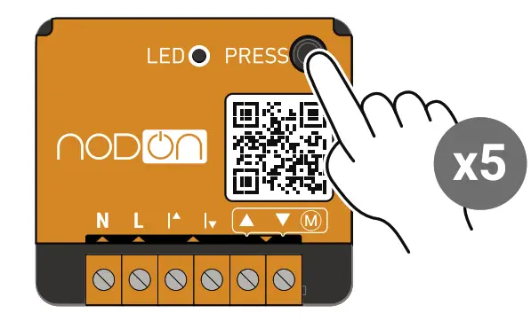 1 Do 5 short presses.
Note: The Relay Switch LED blinks green, meaning the calibration has well started.Or - From the wired wall switch
 1 Put the roller shutter/ awning in position up.
 2 Do 3 times the cycle ”up – stop” with the wired wall switch.
2/3 The roller shutter/awning confirms the auto-calibration by performing a complete cycle ”up/down/up” **.
Cancel the calibration: Perform 5 brief presses. From the wired switch, press once on the switch.
** If the cycle is reversed(down/up/down), switch ![]() and
and![]()
PAIRING THE ROLLER SHUTTER RELAY SWITCH
To add a remote or a wall switch or the Soft Button (EnOcean compatible) you must enter the pairing mode, your light must be switched OFF.
The relay Switch must be power supplied.
Two modes:
- From the Relay Switch
 1 Launch the pairing by doing 3 consecutive presses on the button of the Relay Switch. The LED blinks red.
 2a Remote or wall switch: You have now 30 seconds to pair your controller by briefly pressing on the button of your choice (less than a second), this one will control the rise of your roller shutter/awning.
2b Soft Button: You have now 30 seconds to pair your Soft Button by doing 5 brief consecutive presses on the button.
 3 The Relay Switch LED blinks twice green, confirming the pairing.
Note: if the LED blinks orange during the pairing procedure, it means that more than 22 controllers are paired and that no more controllers can be paired. You must remove one controller to add a new one.Or - From the wired wall switch
 1 Put the roller shutter/ awning on position down.
 2 Do 3 times the cycle “down – stop” with the wired wall switch.
 3 The roller shutter/ awning will rise of 10%.
 4 Remote or wall switch: You have 30 seconds to pair your controller by briefly pressing the button of your choice (less then a second), this one will control the rise of your roller shutter/awning.
 5 The roller shutter/awning confirms the pairing by closing completely.
The Soft Button will work as follows:
| Types of press | Action |
| Single press | Reversal |
| Double press | Open |
| Long press | Closed |

PAIRING
WITH A HOME AUTOMATION GATEWAY
For more details on how to paira home automation gateway or other compatible products, please consult the “Support” section onnodon.fr/en/
UNPAIRING PROCEDURE
Do the same procedure asa pairing (see “pairing procedure”) and takes care of pressing the button chosen to control your gate/ garage door/electric latch or your electrical outlet.
RESET PROCEDURE
SIN-2-RS-01-UG-V3
Relay switch must be power supplied.
- Press more than 5 seconds on your module’s button. The LED blinks orange.
- Press once again the button (short press) to confirm the reset. If the reset is correct, the LED blinks alternatively in red and green and stays green. Start again if necessary.
- Your module has now its original settings.
USE CAUTIONS
- Never use the device if it is not correctly installed and placed inside a connecting box in conformity with the current norms.
- Keep the product far away from liquids.
DETAILED
USER GUIDE
Directly access the detailed user guide on the Support section on nodon.fr/en/technicalsupport/
 https://nodon.fr/en/technical-support
CONTACT
NodOn SAS 121 rue des Hêtres 45590 St CYR EN VAL (FRANCE)
AFTER SALES SERVICE
nodon.fr/en/ “support”section support@nodon.fr
APPROBATIONS ET CERTIFICATIONS
 Hereby, NodOn SAS declares that this radio equipment conforms to the RED directive 2014/53/UE. The integral text of the EU declaration of conformity
is available at the following online address: nodon.fr/en/ ”support” section.
![]() The presence of this symbol on a product indicates that this one is conform to the European directive2012/19/UE. Find out more about the provisions in force in your region regarding the separate collection of electrical and electronic devices. Respect the local rules and do not throw out the product with common domestic waste.The correct rejection of ancient products allows for preserving the environment and health.
The presence of this symbol on a product indicates that this one is conform to the European directive2012/19/UE. Find out more about the provisions in force in your region regarding the separate collection of electrical and electronic devices. Respect the local rules and do not throw out the product with common domestic waste.The correct rejection of ancient products allows for preserving the environment and health.
 This product must be used indoors only.
![]() This product conforms to EnOcean radio protocol.
This product conforms to EnOcean radio protocol.
DANGER OF ELECTROCUTION
![]() BEFORE ANY INSTALLATION MAKE SURE THE POWER SUPPLY IS DISCONNECTED TO AVOID ANY RISK OF ELECTROCUTION.
BEFORE ANY INSTALLATION MAKE SURE THE POWER SUPPLY IS DISCONNECTED TO AVOID ANY RISK OF ELECTROCUTION.
Directly cut the power supply from the breaker box to avoid any risk of electrocution. This relay switch is designed to be used to power up, a wrong installation can create a fire or an electric shock. If you are not confident about electrical installation, please ask a professional. The relay switch must be installed and connected carefully following the instructions of this user guide. We will not be responsible for any loss or damage resulting from a non-respect of the instructions of this user guide. Cut the power supply before any operation and don’t do any modification if the LED is still ON.
Documents / Resources
 |
NODON SIN-2-RS-01 Roller Shutter Relay Switch [pdf] User Guide SIN-2-RS-01, Roller Shutter Relay Switch, SIN-2-RS-01 Roller Shutter Relay Switch, Shutter Relay Switch, Relay Switch, Switch |
 |
nodon SIN-2-RS-01 Roller Shutter Relay Switch [pdf] User Guide SIN-2-RS-01, Roller Shutter Relay Switch, Shutter Relay Switch, Relay Switch, SIN-2-RS-01, Switch |


