Deep Sea Electronics DSE9460 & DSE9461 Installation Instructions
Document Number: 053-147, Issue 4
Installation
The DSE9460 and DSE9461 battery chargers are designed for wall mounting using the four pre-drilled holes on the back of the enclosure. Detailed dimension and mounting information is provided elsewhere in this document. These chargers are designed to be permanently connected to both the AC supply and the load. They do not require disabling during heavy load events, such as engine cranking, or when operating in parallel with a charging alternator.
Battery Suitability
The battery charger is factory configured by Deep Sea Electronics (DSE) to be compatible with Lead Acid batteries. However, it can be adjusted to support other battery types using the DSE Configuration Suite PC Software. It is crucial to ensure that the batteries connected to the charger are of the correct technology to match the charger's current settings.
Indications
The battery charger is equipped with an LCD display. Depending on the specific model variant, additional voltage and current meters may also be fitted.
Boost Mode
Boost mode can be activated automatically or by triggering a digital input, if configured for this function. Activating boost mode increases the battery charger's output voltage to the pre-set boost voltage level.
Accessing the Front Panel Editor
The Front Panel Editor (FPE) allows adjustment of charger parameters. The following steps outline how to access and use it:
- To access the FPE, press and hold the ✔️ button.
- Use the ⬆️ (up) or ⬇️ (down) buttons to cycle through the list of Adjustable Parameters.
- When a parameter is displayed, press the ✔️ button to enter edit mode. The parameter's value will flash to indicate it is ready for editing.
- Use the ➕ (plus) or ➖ (minus) buttons to change the parameter's value to the desired setting.
- Once the value is set, press the ✔️ button to save the selection. The value will stop flashing, indicating the change has been saved.
- To exit the editor, press and hold the ✔️ button.
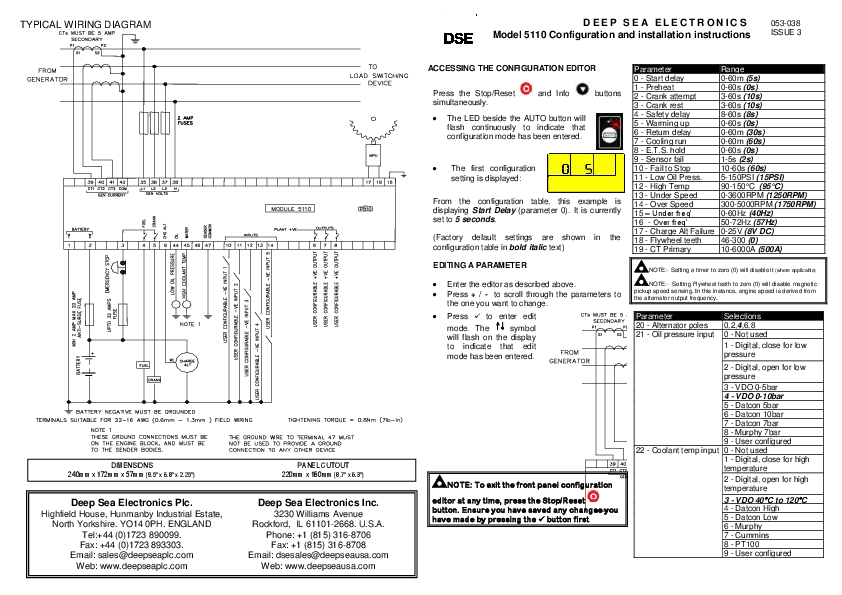
Typical Wiring Diagram Description
This diagram illustrates the typical wiring connections for the DSE9460/DSE9461 models.
Key Connections:
- DC Output: OP+ and OP- terminals are for the main charge output. OP- must be connected directly to the battery.
- AC Input: L (Line) and N (Neutral) terminals connect to the AC supply via an internal AC fuse holder.
- Status Indicators/Inputs:
- CHARGE FAIL RELAY: For reporting charger failure.
- LOCAL DISPLAY: For connecting a local display unit.
- DC SUPPLY: For auxiliary DC power.
- TEMPERATURE SENSOR: Accepts PTC or PT1000 sensors.
- DIGITAL INPUT: For external control signals.
- Communication: RS485 terminals are available for communication.
- Other: [USB] and PROGRAMMING PORT are also indicated.
Important Notes:
- Note 1 (RS485): A 120 Ω termination resistor is required if this unit is the first or last device on an RS485 link.
- Note 2 (AC Input Fuse): Fuse ratings are 6.3A for 110V AC input and 3.5A for 230V AC input. Fuse appropriately, keeping the fuse as close to the charger as possible, especially when the current limit is configured below 10A, to protect the cables.
- Note 3: The unit is factory fitted with a 6.3A anti-surge fuse. Ensure appropriate fusing.
- Note 4: Fuse appropriately and as close to the battery as possible to protect the cables and the battery.
- The "DE-ACTIVATES UPON CHARGER FAILURE" indicator is shown.
Adjustable Parameters
Note: On later versions of the DSE2541 display, only parameters 100 to 108 are available for configuration.
| Index | Parameter | Value |
|---|---|---|
| 100 | Contrast | 0% |
| 101 | Temperature Units | °C, °F |
| 102 | Slave ID | 1 to 255 |
| 103 | Baud Rate | 4800 to 115200 |
| 104 | Enable Alarm Popup Screen | Enable, Disable |
| 105 | Home Page Configuration | 0 to 8 (Home Page List) |
| 106 | Home Page Timeout | 0 s |
| 107 | Sleep Mode Timeout | 0 s |
| 108 | Enable Engineering Page | Enable, Disable |
Parameter 105 - Home Page Configuration Selections
| Value | Home Page List |
|---|---|
| 0 | Analogue Meters |
| 1 | Output Voltage And Current |
| 2 | Output Power And Battery Charger Temperature |
| 3 | Battery Sensed Voltage And Battery Temperature |
| 4 | Mains AC Voltage And Frequency |
| 5 | Battery Charger Model And Charger Software Version |
| 7 | Control Page |
| 8 | Alarms Page |
Display LED Indications
The charger features status LEDs for Charger Status, Fault Status, and Boost Mode.
Charger Status
| Condition | LED State |
|---|---|
| Charger Off | Off |
| Charger On | On |
Fault Status
| Condition | LED State |
|---|---|
| No Fault | Off |
| Warning Fault | On |
| Shutdown Fault | Flashing |
Boost Mode
| Condition | LED State |
|---|---|
| Boost Off | Off |
| Boost On | On |
Dimensions and Mounting
The charger enclosure is designed for indoor use.
| Parameter | Comment |
|---|---|
| Cabinet Type | Custom cabinet for indoor use only |
| Overall Size | 165 mm X 305 mm X 110 mm (6.5" X 12.0" X 4.3") |
| Material | Sheet steel enclosure of all-round solid construction |
| Surface Finish | Powder-coated black |
| Protection Category | IP20, NEMA 1 |
| Weight | 2.3 kg (5 lb 1 oz) |
| Mounting Type | Wall mounted with terminals to bottom. |
| Mounting Holes | Diameter 6 mm (0.2"), 63 mm X 284 mm (3.4" x 11.2") centres |
| Operating Temperature (With Deratings) | -30 °C to +80 °C (-22 °F to +176 °F) |
Requirements for UL Certification
| Parameter | Comment |
|---|---|
| Screw Terminal Tightening Torque | 4.5 lb-in (0.5 Nm) |
| Conductors |
|
| Communication Circuits Mounting | Must be connected to communication circuits of UL Listed equipment. |
| Operating Temperature |
|
| Storage Temperature | -40 °F to +176 °F (-40 °C to +80 °C) |
Safety Warning
DANGER OF DEATH: LIVE PARTS exist within the enclosure. The enclosure cover must not be removed when connected to an AC supply.