Deep Sea Electronics Model 5110 Configuration and Installation Guide
Document Version: 053-038 ISSUE 3
Accessing the Configuration Editor
To access the configuration editor:
- Press the Stop/Reset and Info buttons simultaneously.
- The LED beside the AUTO button will flash continuously, indicating that configuration mode has been entered.
- The first configuration setting will be displayed. For example, the display might show 'Start Delay (parameter 0)', currently set to 5 seconds. (Factory default settings are shown in the configuration table in bold italic text).
Editing a Parameter
- Enter the editor as described above.
- Press the + / - buttons to scroll through the parameters to the one you wish to change.
- Press the ✓ (Checkmark) button to enter edit mode. The ↑ (Up Arrow) symbol will flash on the display to indicate that edit mode has been entered.
Note: To exit the front panel configuration editor at any time, press the Stop/Reset button. Ensure you have saved any changes by pressing the ✓ button first.
Parameter Configuration Table
| Parameter | Range |
|---|---|
| 0 - Start delay | 0-60m (5s) |
| 1 - Preheat | 0-60s (0s) |
| 2 - Crank attempt | 3-60s (10s) |
| 3 - Crank rest | 3-60s (10s) |
| 4 - Safety delay | 8-60s (8s) |
| 5 - Warming up | 0-60s (0s) |
| 6 - Return delay | 0-60m (30s) |
| 7 - Cooling run | 0-60m (60s) |
| 8 - E.T.S. hold | 0-60s (0s) |
| 9 - Sensor fail | 1-5s (2s) |
| 10 - Fail to Stop | 10-60s (60s) |
| 11 - Low Oil Press. | 5-150 PSI (15 PSI) |
| 12 - High Temp | 90-150°C (95°C) |
| 13 - Under Speed | 0-3600 RPM (1250 RPM) |
| 14 - Over Speed | 300-5000 RPM (1750 RPM) |
| 15 - Under freq | 0-60 Hz (40 Hz) |
| 16 - Over freq | 50-72 Hz (57 Hz) |
| 17 - Charge Alt Failure | 0-25V (8V DC) |
| 18 - Flywheel teeth | 46-300 (0) |
| 19 - CT Primary | 10-6000A (500A) |
Note: Setting a timer to zero (0) will disable it (where applicable).
Note: Setting 'Flywheel teeth' to zero (0) will disable magnetic pickup speed sensing. In this instance, engine speed is derived from the alternator output frequency.
| Parameter | Selections |
|---|---|
| 20 - Alternator poles | 0, 2, 4, 6, 8 |
| 21 - Oil pressure input | 0 - Not used 1 - Digital, close for low pressure 2 - Digital, open for low pressure 3 - VDO 0-5bar 4 - VDO 0-10bar 5 - Datcon 5bar 6 - Datcon 10bar 7 - Datcon 7bar 8 - Murphy 7bar 9 - User configured |
| 22 - Coolant temp input | 0 - Not used 1 - Digital, close for high temperature 2 - Digital, open for high temperature 3 - VDO 40°C to 120°C 4 - Datcon High 5 - Datcon Low 6 - Murphy 7 - Cummins 8 - PT100 9 - User configured |
| 23 - Fast loading enabled | 0 - No 1 - Yes |
| 24 - AC system | 0 - 3 phases 4 wires 1 - 1 phase 2 wire 2 - 3 phases 3 wires 3 - 2 phases 3 wires |
| 25 - Oil pressure display units | 0 - Bar/PSI 1 - kPa |
| 26 - Output 1 | 0 - Unused 1 - Preheat mode 0 2 - Air flap 3 - Close Generator 4 - Energise to stop 5 - Engine running 6 - Shutdown alarm 7 - System in auto 8 - Auxiliary input 1 active 9 - Auxiliary input 2 active 10 - Auxiliary input 3 active 11 - Auxiliary input 4 active 12 - Auxiliary input 5 active 13 - Preheat mode 1 14 - Preheat mode 2 15 - Preheat mode 3 16 - Warning alarm 17 - Common alarm 18 - Maintenance due |
| 27 - Output 2 | 0 - Unused 1 - Preheat mode 0 2 - Air flap 3 - Close Generator 4 - Energise to stop 5 - Engine running 6 - Shutdown alarm 7 - System in auto 8 - Auxiliary input 1 active 9 - Auxiliary input 2 active 10 - Auxiliary input 3 active 11 - Auxiliary input 4 active 12 - Auxiliary input 5 active 13 - Preheat mode 1 14 - Preheat mode 2 15 - Preheat mode 3 16 - Warning alarm 17 - Common alarm 18 - Maintenance due |
| 28 - Output 3 | 0 - Unused 1 - Preheat mode 0 2 - Air flap 3 - Close Generator 4 - Energise to stop 5 - Engine running 6 - Shutdown alarm 7 - System in auto 8 - Auxiliary input 1 active 9 - Auxiliary input 2 active 10 - Auxiliary input 3 active 11 - Auxiliary input 4 active 12 - Auxiliary input 5 active 13 - Preheat mode 1 14 - Preheat mode 2 15 - Preheat mode 3 16 - Warning alarm 17 - Common alarm 18 - Maintenance due |
| 29 - LCD 1 | 0 - Unused 1 - Preheat mode 0 2 - Air flap 3 - Close Generator 4 - Energise to stop 5 - Engine running 6 - Shutdown alarm 7 - System in auto 8 - Auxiliary input 1 active 9 - Auxiliary input 2 active 10 - Auxiliary input 3 active 11 - Auxiliary input 4 active 12 - Auxiliary input 5 active 13 - Preheat mode 1 14 - Preheat mode 2 15 - Preheat mode 3 16 - Warning alarm 17 - Common alarm 18 - Maintenance due |
| 30 - LCD 2 | 0 - Unused 1 - Preheat mode 0 2 - Air flap 3 - Close Generator 4 - Energise to stop 5 - Engine running 6 - Shutdown alarm 7 - System in auto 8 - Auxiliary input 1 active 9 - Auxiliary input 2 active 10 - Auxiliary input 3 active 11 - Auxiliary input 4 active 12 - Auxiliary input 5 active 13 - Preheat mode 1 14 - Preheat mode 2 15 - Preheat mode 3 16 - Warning alarm 17 - Common alarm 18 - Maintenance due |
| 31 - LCD 3 | 0 - Unused 1 - Preheat mode 0 2 - Air flap 3 - Close Generator 4 - Energise to stop 5 - Engine running 6 - Shutdown alarm 7 - System in auto 8 - Auxiliary input 1 active 9 - Auxiliary input 2 active 10 - Auxiliary input 3 active 11 - Auxiliary input 4 active 12 - Auxiliary input 5 active 13 - Preheat mode 1 14 - Preheat mode 2 15 - Preheat mode 3 16 - Warning alarm 17 - Common alarm 18 - Maintenance due |
| 32 - LCD 4 | 0 - Unused 1 - Preheat mode 0 2 - Air flap 3 - Close Generator 4 - Energise to stop 5 - Engine running 6 - Shutdown alarm 7 - System in auto 8 - Auxiliary input 1 active 9 - Auxiliary input 2 active 10 - Auxiliary input 3 active 11 - Auxiliary input 4 active 12 - Auxiliary input 5 active 13 - Preheat mode 1 14 - Preheat mode 2 15 - Preheat mode 3 16 - Warning alarm 17 - Common alarm 18 - Maintenance due |
| 33 - Input 1 | 0 - Delayed, Warning, close to activate 1 - Delayed, Warning, open to activate 2 - Immediate, Warning, close to activate 3 - Immediate, Warning, open to activate 4 - Delayed, Shutdown, close to activate 5 - Delayed, Shutdown, open to activate 6 - Immediate, Shutdown, close to activate 7 - Immediate, Shutdown, open to activate 8 - Remote Start, close to activate 9 - Remote Start, open to activate |
| 34 - Input 2 | 0 - Delayed, Warning, close to activate 1 - Delayed, Warning, open to activate 2 - Immediate, Warning, close to activate 3 - Immediate, Warning, open to activate 4 - Delayed, Shutdown, close to activate 5 - Delayed, Shutdown, open to activate 6 - Immediate, Shutdown, close to activate 7 - Immediate, Shutdown, open to activate 8 - Electrical trip, close to activate 9 - Electrical trip, open to activate |
| 35 - Input 3 | 0 - Delayed, Warning, close to activate 1 - Delayed, Warning, open to activate 2 - Immediate, Warning, close to activate 3 - Immediate, Warning, open to activate 4 - Delayed, Shutdown, close to activate 5 - Delayed, Shutdown, open to activate 6 - Immediate, Shutdown, close to activate 7 - Immediate, Shutdown, open to activate 8 - Lamp test, close to activate 9 - Lamp test, open to activate |
| 36 - Input 4 | 0 - Delayed, Warning, close to activate 1 - Delayed, Warning, open to activate 2 - Immediate, Warning, close to activate 3 - Immediate, Warning, open to activate 4 - Delayed, Shutdown, close to activate 5 - Delayed, Shutdown, open to activate 6 - Immediate, Shutdown, close to activate 7 - Immediate, Shutdown, open to activate 8 - Lamp test, close to activate 9 - Lamp test, open to activate |
| 37 - Input 5 | 0 - Delayed, Warning, close to activate 1 - Delayed, Warning, open to activate 2 - Immediate, Warning, close to activate 3 - Immediate, Warning, open to activate 4 - Delayed, Shutdown, close to activate 5 - Delayed, Shutdown, open to activate 6 - Immediate, Shutdown, close to activate 7 - Immediate, Shutdown, open to activate 8 - Oil pressure, Shutdown, close to activate 9 - Oil pressure, Shutdown, open to activate |
Note on Preheat Modes:
- Preheat mode 0: Preheat during preheat timer, ceasing at the end of the preheat timer.
- Preheat mode 1: Preheat during preheat timer and continue until the engine stops cranking.
- Preheat mode 2: Preheat during preheat timer and continue until the safety delay timer has expired.
- Preheat mode 3: Preheat during preheat timer and continue until the warming timer has expired.
In all preheat modes, preheat also occurs during the crank rest timer between crank cycles.
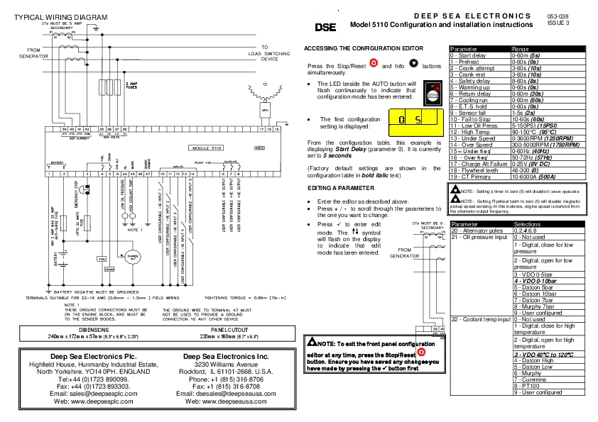
Wiring Diagram Description
The diagram illustrates the typical wiring for the Module 5110. Key components include:
- FROM GENERATOR: Connections for generator output, including current transformers (CTs) for GEN CURRENT (Terminals 39-42) and GEN VOLTS (Terminals 35-38).
- MODULE 5110: The central control unit with various input and output terminals.
- BATTERY: Connections for the DC power supply (Terminals 1-2), including an anti-surge fuse and an emergency stop fuse.
- INPUTS: Terminals for various sensor inputs such as FUEL, CRANK, CHG ALT, OIL PRESSURE, LOW OIL PRESSURE, HIGH COOLANT TEMP, WATER, and SENDER COMMON (Terminals 3-9, 44-47). Also includes user-configurable inputs (Terminals 10-14).
- OUTPUTS: Terminals for user-configurable outputs (Terminals 6-8).
- MPU (Magnetic Pickup Unit): Connected to terminals 17 and 18 for engine speed sensing. Terminal 16 is for ground.
- Fuses: 2 Amp fuses are shown protecting the generator voltage inputs.
- Grounding: Battery negative must be grounded. Ground connections must be on the engine block and to sender bodies. The ground wire to terminal 47 must not be used to provide a ground connection to any other device.
- Tightening Torque: Specified as 0.8 Nm (7 lb-in).
Dimensions
Module Dimensions: 240mm x 172mm x 57mm (9.5" x 6.8" x 2.25")
Panel Cutout: 220mm x 160mm (8.7" x 6.3")


