Deep Sea Electronics DSE8910 & DSE8920 Installation Instructions
Document Number: 053-248 | Issue: 1
Manufacturer: Deep Sea Electronics
Website: www.deepseaelectronics.com
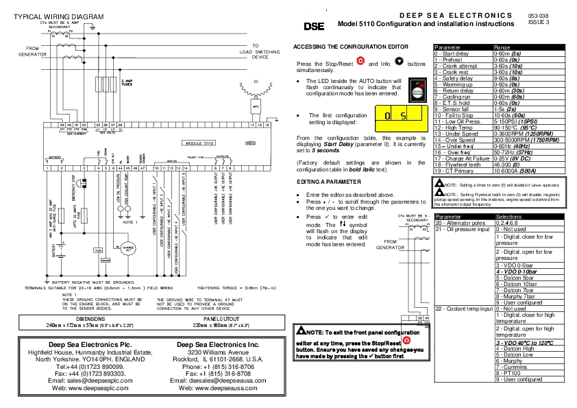
Typical Wiring Diagram
? NOTE: Larger versions of the Typical Wiring Diagrams are available in the products' operator manuals. Refer to DSE Publication: 057-310 DSE8910 Operator Manual & 057-311 DSE8920 Operator Manual, both available from www.deepseaelectronics.com.
The diagram illustrates the typical wiring connections for the DSE8910 and DSE8920 modules. Key connections include:
- Battery: +VE and -VE terminals, with appropriate fuses.
- Engine Controls: Fuel, Start, Charge Alternator.
- Generator Output: Flexible outputs, connected to Automatic ACB/MCCB.
- Mains Input: Connected to Automatic ACB/MCCB.
- Current Transformers (CTs): For generator and mains current measurement (1 or 5 Amp, secondary).
- Analogue Inputs: Common, Oil Pressure Sensor, Coolant Temp Sensor, Fuel Level Sensor, Flexible Sensor.
- Digital Inputs: 12 configurable -VE inputs.
- DC Outputs: 6 configurable +VE outputs.
- Communication Ports: RS485, CAN, Ethernet (RJ45).
- Programming Port: USB Host.
- Control Connections: To Governor, To AVR.
- Earth Connections: Terminal 56 is CT common. Specific notes detail grounding requirements, DSENet termination resistors, and CT common placement.
Installation Instructions
Accessing the Running Configuration Editor
The Running Configuration Editor can be accessed without stopping the generator. All protections remain active.
- Press and hold the ✔️ [tick] button to enter the Running Configuration Editor.
Editing a Parameter
- Enter the Running Configuration Editor as described above.
- Press the ⬆️ [up] or ⬇️ [down] buttons to select the section to view/change. The current selected section highlights in green.
- Press the ⬅️ [left] or ➡️ [right] buttons to select the Subsection/Parameter to be edited. The current selected item highlights in green.
- To edit the parameter, press the ✔️ [tick] button. The parameter is no longer highlighted green, indicating it is in edit mode.
- Press the ⬆️ [up] or ⬇️ [down] buttons to change the parameter to the required value.
- Press the ✔️ [tick] button to save the value. The parameter highlights green to indicate it has been saved.
- To exit the editor and save the changes, press and hold the ✔️ [tick] button.
Selecting the DSE8910 or DSE8920 Software Application
- Ensure the generator is at rest by pressing the Stop/Reset Mode ⏹️ [stop] button.
- Enter the Running Configuration Editor as described above.
- Press the ⬆️ [up] or ⬇️ [down] buttons to navigate to the MODEL TYPE section. The section highlights in green when selected.
- Press the ➡️ [right] button to select the MODEL SELECTION parameter. The parameter highlights in green when selected.
- Press the ⬆️ [up] or ⬇️ [down] buttons to change between DSE8910 and DSE8920. By default, DSE8920 is selected.
- Press the ✔️ [tick] button to change the software application; a confirmation box appears.
- Press the ⬅️ [left] or ➡️ [right] buttons to select YES to confirm the software application change.
- When prompted, remove the power supply to the module and then reapply it. The module powers up in the newly selected software application.
? NOTE: If the editor is left inactive for the duration of the LCD Page Timer, it is automatically exited to ensure security.
Panel Fascia Fixing Clips
? NOTE: In conditions of excessive vibration, mount the module on suitable anti-vibration mountings.
The module is held into the panel fascia using the supplied fixing clips:
- Withdraw the fixing clip screw (turn anticlockwise) until only the pointed end is protruding from the clip.
- Insert the three 'prongs' of the fixing clip into the slots in the side of the module case.
- Pull the fixing clip backwards (towards the back of the module) ensuring all three prongs of the clip are inside their allotted slots.
- Turn the fixing clip screws clockwise until they make contact with the panel fascia.
- Turn the screw a quarter of a turn to secure the module into the panel fascia. Care must be taken not to over tighten the fixing clip screws.
Requirements for UL Certification
⚠️ WARNING!: More than one live circuit exists, see diagram overleaf for further information.
❗ ATTENTION!: Several live circuits exist. See the diagram overleaf for more information.
| Specification | Description |
|---|---|
| Screw Terminal Tightening Torque | 4.5 lb-in (0.5 Nm) |
| Conductors |
|
| Current Inputs | - |
| Communication Circuits | - |
| DC Output Pilot Duty | 0.5 A |
| Mounting | Suitable for flat surface mounting in Type 1 Enclosure Type rating with surrounding air temperature -22 °F to +122 °F (-30 °C to +50 °C). Suitable for pollution degree 3 environments when voltage sensing inputs do not exceed 300 V. When used to monitor voltages over 300 V, device to be installed in an unventilated or filtered ventilation enclosure to maintain a pollution degree 2 environment. |
| Operating Temperature | -22 °F to +122 °F (-30 °C to +50 °C) |
Dimensions and Mounting
| Parameter | Specification |
|---|---|
| Dimensions | 310 mm X 162 mm X 51.3 mm (12.2" X 6.38 " X 2.02 ") |
| Panel Cutout | 282 mm X 136 mm (11.10” X 5.35") |
| Weight | 1.19 kg (2.62 lb) |
| Operating Temperature | -40 °C to +70 °C (-40 °F to +158 °F) |
| Storage Temperature | -40 °C to +80 °C (-40 °F to +176 °F) |