GW1101-1DI(3IN1)-DB-P(12-48VDC) Modbus Gateway Quick Installation Guide
Company Information
3onedata Co., Ltd.
Address: 3/B, Zone 1, Baiwangxin High Technology Industrial Park, Xili, Nanshan District, Shenzhen
Website: www.3onedata.com
Tel: +86 0755-26702688
Fax: +86 0755-26703485
Package Checklist
Please check whether the package and accessories are intact while using the device for the first time.
- Modbus gateway × 1
- Power adapter
- Straight-through cable
- Certification
- Warranty card
If any of these items are damaged or lost, please contact 3onedata Co., Ltd. or its dealers for assistance.
Product Overview
The product is a managed wall-mounted industrial Modbus gateway. The model is GW1101-1DI(3IN1)-DB-P(12-48VDC). It features one 3IN1 serial port with isolation, one 100M copper Ethernet port, and supports a 12~48VDC power supply.
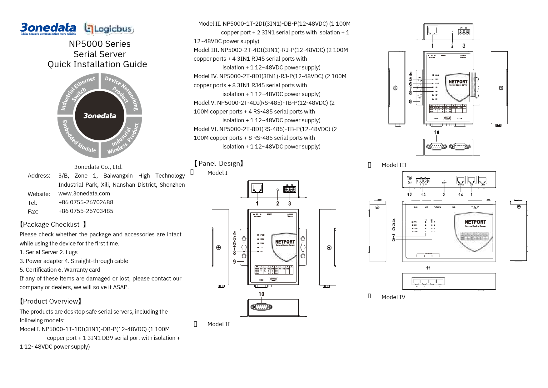
Panel Design
Diagram showing the top, bottom, front, and side views of the Modbus Gateway. The front view highlights numbered components:
- 1. Terminal block for power input
- 2. Reset button
- 3. 100M copper port
- 4. RS-232/485/422 3IN1 serial port
- 5. Power supply indicator PWR
- 6. Running indicator RUN
- 7. Copper port indicator LINK
- 8. Serial port transmitting indicator
- 9. Serial port receiving indicator
- 10. Lug
Mounting Dimension
Unit: mm. Diagram showing mounting dimensions. Key dimensions include 97mm width, 85.8mm height, 25mm depth, and mounting hole spacing.
Serial Port Connection
This device provides one 3IN1 serial port, which supports RS232, RS485, and RS422 simultaneously. The interface type is DB9 male. The pin definitions are as follows:
| PIN | RS-232 | RS-422 | RS-485 |
|---|---|---|---|
| 1 | T+ | D+ | |
| 2 | RXD | T- | D- |
| 3 | TXD | R+ | |
| 4 | DTR | R- | |
| 5 | GND | GND | GND |
| 6 | DSR | - | - |
| 7 | RTS | - | - |
| 8 | CTS | - | - |
| 9 |
Mounting Instructions
Notice Before Mounting
- Do not place or install the device in areas near water or moisture. Keep the relative humidity of the device's surrounding between 5%~95% without condensation.
- Before powering on, confirm the supported power supply specification to avoid over-voltage damaging the device.
- The device surface temperature can become high after running; avoid direct contact to prevent scalding.
Wall-mounted Device Mounting
- On the wall for mounting, place the device for reference or refer to the mounting dimension to mark two screw positions.
- Nail M4 screws on the wall and keep a 2mm interspace reserved.
- Hang the device on the two screws and slide downward, then tighten the screws to enhance stability. Mounting is complete.
Notice before power on
- Power ON operation: First insert the power supply terminal block into the device's power supply interface, and then plug the power supply plug and power on.
- Power OFF operation: First unplug the power plug, then remove the power line. Please note the operation order above.
Power Supply Connection
This device provides a 1 DC power supply via a 3-pin 5.08mm pitch terminal block. The power supply supports non-polarity. The power supply range is 12~48VDC. The pin definitions of the terminals are shown as follows:
| PIN | Definition |
|---|---|
| 1 | V+ |
| 2 | FG |
| 3 | V- |
Diagram showing the 3-pin power supply terminal block with pins labeled V+, FG, and V-.
Reset Button Setting
This device provides one reset button. Press and hold the button for 4-5 seconds, then release it to restore factory defaults.
Checking LED Indicator
The device provides LED indicators to monitor the device's working status, offering a comprehensive, simplified troubleshooting guide. The detailed status of each LED is described in the table below:
| LED | Indicate | Description |
|---|---|---|
| PWR | ON | PWR is connected and running normally. |
| OFF | PWR is disconnected and running abnormally. | |
| RUN | ON | The device is powered on or the device is abnormal. |
| OFF | The device is powered off or the device is abnormal. | |
| LINK | Blinking (once per second) | Blink once per second, device is running normally. |
| ON | Copper port has established an active network connection. | |
| Blinking | Copper port is in a network activity state. | |
| OFF | Copper port has not established an active network connection. | |
| TX | OFF | No data or abnormal data is being transmitted through serial port. |
| Blinking | Serial port is transmitting data. | |
| RX | OFF | Serial port is not receiving data or receiving data abnormally. |
| Blinking | Serial port is receiving data. |
Logging in to WEB Interface
This device supports WEB management and configuration. A computer can access the device via its Ethernet interface. The procedure for logging into the device's configuration interface via a web browser is shown below:
- Configure the IP addresses of the computer and the device to be in the same network segment, ensuring they can be mutually accessed.
- Enter the device's IP address in the address bar of the computer browser. The default IP address is "192.168.1.254".
- Enter the device's username and password in the login window. The default username and password are "admin".
- Click the "OK" button to log in to the WEB interface of the device.
Specifications
| Category | Sub-Category/Label | Details |
|---|---|---|
| Panel | 100M Copper Port | 10/100Base-T(X) self-adapting RJ45 port |
| Serial Port | RS-232/485/422 3IN1 serial port, DB9 interface | |
| Indicator | Power indicator, network Link/Act indicator, serial port transmission and receiving data indicator, running indicator | |
| Power Supply | Input power supply | 12~48VDC |
| Access terminal block | 3-pin 5.08mm pitch terminal blocks | |
| Power Consumption | No-load | 0.9W@12VDC |
| Full-load | 1.1W@12VDC | |
| Working Environment | Working temperature | -40~75°C |
| Storage temperature | -40~85°C | |
| Working humidity | 5%~95%(no condensation) | |
| Protection grade | IP40 (metal shell) |