GW1114-4DI(3IN1)-RJ-P(12-48VDC) Modbus Gateway Quick Installation Guide
Product Overview
The GW1114-4DI(3IN1)-RJ-P(12-48VDC) is a wall-mounted MODBUS gateway device. It features 4 RS-485/422/232 serial ports with isolation, 2 100M copper ports, and supports 12-48VDC power supply.
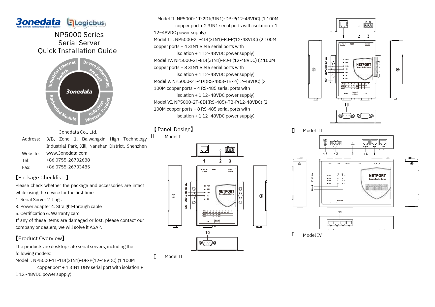
The device features a panel design with views from Top, Front, Rear, Left, Right, and Bottom, illustrating the physical layout and component placement.
Device Components
- 1. Power indicator: Indicates power status.
- 2. Running indicator: Indicates system running status.
- 3. Copper port connection indicator: Shows copper port network connection status.
- 4. Serial port transmission data indicators: Show serial port transmission activity.
- 5. Serial port receiving data indicators: Show serial port receiving activity.
- 6. Grounding screw: For device grounding.
- 7. Terminal blocks for power input: Connects DC power supply.
- 8. Reset button: Restores factory defaults.
- 9. Console port: For console access.
- 10. 100M copper port: Ethernet RJ45 port.
- 11. RS-485/422/232 serial port: RJ45 serial port.
- 12. Foot pad: Provides stability.
- 13. Wall mounting location hole: For wall mounting.
Mounting
Notice Before Mounting
- Avoid placing or installing the device in areas near water or moisture. Maintain relative humidity between 5%~95% without condensation.
- Before powering on, confirm the supported power supply specification to prevent over-voltage damage.
- The device surface may become hot after running; avoid direct contact to prevent scalding.
Wall-mounted Device Mounting
Step 1: Attach the left/right mounting boards to the device's backboard using M3 screws.
Step 2: Position the device on the wall for reference or use the mounting dimensions to mark two screw positions.
Step 3: Install M4 screws into the wall, leaving a 2mm interspace.
Step 4: Hang the device onto the two screws, slide it downward, and tighten the screws for stability.
Wall-mounted Device Disassembling
Step 1: Power off the device.
Step 2: Unscrew the wall mounting screws by approximately 2mm.
Step 3: Lift the device slightly upward, remove it, and disassembling is complete.
Power Supply
Notice Before Power On
Power ON: Insert the power supply terminal block into the device's power supply interface, then plug in the power supply and turn it on.
Power OFF: Unplug the power supply first, then remove the power line. Follow this order.
Power Supply Connection
The device supports one DC power input via a 3-Pin 5.08mm pitch terminal block. V+ and V- are for DC input, and FG is for power grounding. The power supply is non-polar and supports a range of 12-48VDC.
Reset Button
Reset Button Setting
Press and hold the reset button for 4-5 seconds, then release it to restore the device to factory default settings.
Serial Port Connection
The device features 4 3IN1 serial ports supporting RS232, RS485, and RS422 simultaneously. The interface type is RJ45. Pin definitions are provided below:
| PIN | RS-232 | RS-485 | RS-422 |
|---|---|---|---|
| 1 | DSR | -- | -- |
| 2 | RTS | -- | T+ |
| 3 | GND | GND | GND |
| 4 | TXD | -- | T- |
| 5 | RXD | D+ | R- |
| 6 | DCD | D- | R+ |
| 7 | CTS | -- | -- |
| 8 | DTR | -- | -- |
LED Indicators
LED indicators monitor device status for simplified troubleshooting.
| LED | Status | Description |
|---|---|---|
| PWR | ON | PWR is connected and running normally. |
| PWR | OFF | PWR is disconnected and running abnormally. |
| RUN | Blinking | The system is running normally. |
| RUN | OFF | The system is not running or running abnormally. |
| RUN | ON | System is running abnormally. |
| LINK (1-2) | Blinking | Copper port has established an active network connection. |
| LINK (1-2) | OFF | Copper port has not established an active network connection. |
| TX (1-4) | OFF | Serial port is not transmitting data or transmitting data abnormally. |
| TX (1-4) | Blinking | Serial port is transmitting data. |
| RX (1-4) | OFF | Serial port is not receiving data or receiving data abnormally. |
| RX (1-4) | Blinking | Serial port is receiving data. |
Web Interface Login
The device supports WEB management and configuration accessible via its Ethernet interface.
Login Procedure
Step 1: Configure your computer's IP address to be in the same network segment as the device. Network Port 1 is in segment '1', and Network Port 2 is in segment '8'. Ensure mutual network accessibility.
Step 2: Enter the device's IP address into your computer's web browser address bar.
Step 3: Enter the device's username and password in the login window. The default username and password are "admin".
Step 4: Click the "OK" button to log in to the device's WEB interface.
Important Notes
- Default IP addresses: Network Port 1 is "192.168.1.254", Network Port 2 is "192.168.8.254".
- If username or password is lost, restore factory settings via the reset button or management software. Note that this clears all configurations, so back up your configuration file beforehand.
- Refer to the user manual for detailed configuration methods and network management functions.
Specifications
Panel
- 100M Copper Port: 10/100Base-T(X) self-adapting RJ45 port.
- Serial Port: 3IN1 RJ45 interface with isolation.
- Indicator: Power indicator, Running indicator, Copper port connection indicator, Serial port transmission and receiving data indicators.
Power Supply
- Input: 12~48VDC.
- Connection: 3 pins 5.08mm pitch terminal blocks.
- Power Consumption: No-load: 3.4W@12VDC; Full-load: 4.1W@12VDC.
Working Environment
- Working temperature: -40~75°C.
- Storage temperature: -40~85°C.
- Working humidity: 5%~95% (no condensation).
- Protection grade: IP40 (metal shell).