NP5000 Series Serial Server Quick Installation Guide
Manufacturer: 3onedata Co., Ltd.
Address: 3/B, Zone 1, Baiwangxin High Technology Industrial Park, Xili, Nanshan District, Shenzhen
Website: www.3onedata.com
Tel: +86 0755-26702688
Fax: +86 0755-26703485
Package Checklist
Please check the package and accessories upon first use. If any items are damaged or lost, contact the company or dealers.
- Serial Server
- Lugs
- Power adapter
- Straight-through cable
- Certification
- Warranty card
Product Overview
The NP5000 series are desktop safe serial servers. The following models are included:
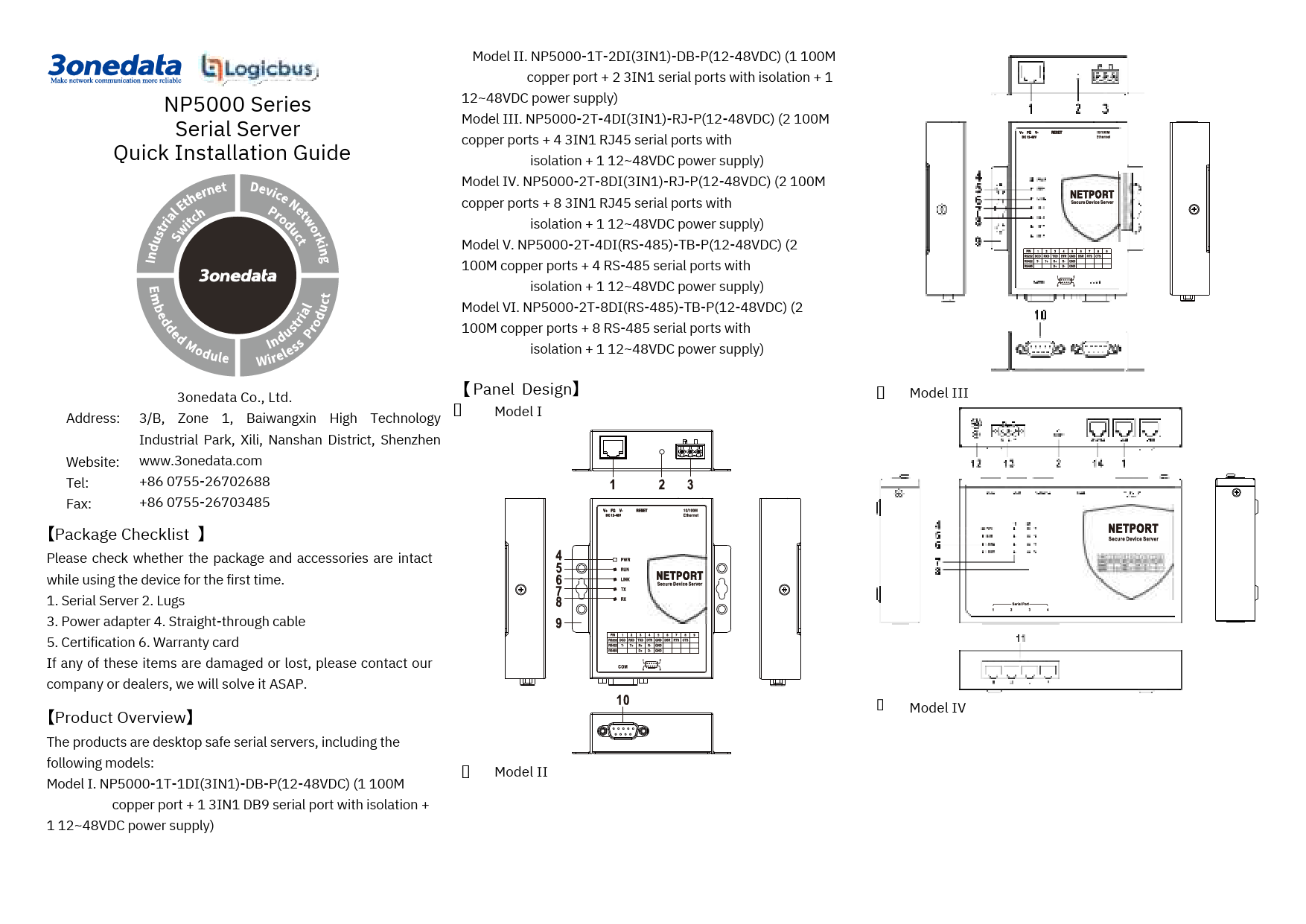
- Model I: NP5000-1T-1DI(3IN1)-DB-P(12-48VDC) (1 100M copper port + 1 3IN1 DB9 serial port with isolation + 1 12-48VDC power supply)
- Model II: NP5000-1T-2DI(3IN1)-DB-P(12-48VDC) (1 100M copper port + 2 3IN1 serial ports with isolation + 1 12~48VDC power supply)
- Model III: NP5000-2T-4DI(3IN1)-RJ-P(12-48VDC) (2 100M copper ports + 4 3IN1 RJ45 serial ports with isolation + 1 12~48VDC power supply)
- Model IV: NP5000-2T-8DI(3IN1)-RJ-P(12-48VDC) (2 100M copper ports + 8 3IN1 RJ45 serial ports with isolation + 1 12~48VDC power supply)
- Model V: NP5000-2T-4DI(RS-485)-TB-P(12-48VDC) (2 100M copper ports + 4 RS-485 serial ports with isolation + 1 12~48VDC power supply)
- Model VI: NP5000-2T-8DI(RS-485)-TB-P(12-48VDC) (2 100M copper ports + 8 RS-485 serial ports with isolation + 1 12~48VDC power supply)
Panel Design and Components
The devices feature various ports and indicators. The specific layout varies by model.
Component Descriptions:
- 100M copper port
- Reset button
- Terminal block 1 for power input
- Power indicator
- Running indicator
- Copper port connection indicator
- Serial port transmission data indicators
- Serial port receiving data indicators
- Lugs
- RS-485/422/232 DB9 serial port
- RS-485/422/232 RJ45 serial port
- Grounding screw
- Terminal block 2 for power input
- Console port
- RS-485 serial port
Note: Visual diagrams of panel layouts for Model I, II, III, IV, V, and VI are present in the original document, showing the physical arrangement of these components.
Mounting
Mounting dimensions are provided in millimeters (mm).
Mounting Notices:
- Do not install near water or moisture. Maintain relative humidity between 5% and 95% without condensation.
- Confirm the supported power supply specification before powering on to prevent over-voltage damage.
- The device surface may become hot after running; avoid direct contact to prevent scalding.
Wall-mounted Device Mounting:
For Model I, II:
- Place the device on the wall for reference or use the mounting dimensions to mark two screw positions.
- Nail M4 screws into the wall, leaving a 2mm interspace.
- Hang the device onto the screws, slide it downwards, and tighten the screws to enhance stability.
For Model III, IV, V, VI:
- Install the left/right mounting board onto the device backboard using M3 screws.
- Place the device on the wall for reference or use the mounting dimensions to mark two screw positions.
- Nail M4 screws into the wall, leaving a 2mm interspace.
- Hang the device onto the screws, slide it downwards, and tighten the screws to enhance stability.
Wall-mounted Device Disassembling:
- Power off the device.
- Unscrew the wall screws by approximately 2mm.
- Lift the device upwards slightly and remove it.
Power Connection and Operation
Notice Before Power On:
- Power ON operation: First, insert the power supply terminal block into the device's power supply interface, then plug in the power supply contact to power on.
- Power OFF operation: First, unpin the power plug, then remove the power line. Please follow this order.
Power Supply Connection:
For Model I, II:
Provides 1 DC power supply input via a 3-pin 5.08mm pitch terminal block. The power supply supports non-polarity and anti-reverse connection. Power supply range: 12-48VDC.
| PIN | Definition |
|---|---|
| 1 | V+ |
| 2 | FG (Frame Ground) |
| 3 | V- |
For Model III, IV, V, VI:
Provide 1 DC power supply input terminal blocks. V+ and V- are for DC input, and FG is for power grounding input. The power supply supports non-polarity. Power supply range: 12-48VDC.
Reset Button Setting
Press and release the reset button for 4-5 seconds to restore the device to factory defaults. ⚙️
Serial Port Connection
RS-485/422/232 DB9 Serial Port (Model I, II)
These models provide 1 or 2 3IN1 DB9 serial ports, supporting RS-232, RS-485, and RS-422 simultaneously. The interface is a DB9 male connector.
| PIN | RS-232 | RS-422 | RS-485 |
|---|---|---|---|
| 1 | DCD | T- | - |
| 2 | RXD | T+ | - |
| 3 | TXD | R+ | D+ |
| 4 | DTR | R- | D- |
| 5 | GND | GND | GND |
| 6 | DSR | - | - |
| 7 | RTS | - | - |
| 8 | CTS | - | - |
| 9 | - | - | - |
RS-485/422/232 RJ45 Serial Port (Model III, IV)
These models provide 4 or 8 3IN1 RJ45 serial ports, supporting RS-232, RS-485, and RS-422 simultaneously. The interface is an RJ45 connector.
Pin Definitions (RJ45):
| Pin No. | RS-232 | RS-422 | RS-485 |
|---|---|---|---|
| 1 | TXD | T+ | D+ |
| 2 | RXD | T- | D- |
| 3 | GND | R+ | GND |
| 4 | DTR | R- | - |
| 5 | DSR | - | - |
| 6 | RTS | - | - |
| 7 | CTS | - | - |
| 8 | DCD | - | - |
RS-485 Serial Port (Model V)
Model V provides 4 RS-485 serial ports using 3-pin 5.08mm pitch terminal blocks.
| PIN | Definition |
|---|---|
| 1 | D+ |
| 2 | D- |
| 3 | GND |
RS-485 Serial Port (Model VI)
Model VI provides 8 RS-485 serial ports using 4 6-pin 5.08mm pitch terminal blocks. Each terminal block supports 2 serial ports.
Serial Port Pin Definitions:
| PIN | Port 1/3/5/7 | Port 2/4/6/8 |
|---|---|---|
| 1 | D+ | D+ |
| 2 | D- | D- |
| 3 | GND | GND |
| 4 | - | D+ |
| 5 | - | D- |
| 6 | - | GND |
Console Port Connection
Models III, IV, V, and VI include a console port (RS232 serial) via an RJ45 connector for device CLI command line management when connected to a PC.
RJ45 Console Port Pin Definition:
| Pin No. | Pin Definition |
|---|---|
| 2 | TXD |
| 3 | RXD |
| 5 | GND |
LED Indicator Status
The device provides LED indicators for monitoring operational status and troubleshooting.
| LED | Indicate State | Description |
|---|---|---|
| PWR | ON | Power is connected and running normally. |
| OFF | Power is disconnected or running abnormally. | |
| Blinking | The system is running normally. | |
| RUN | OFF | The system is not running or running abnormally. |
| ON | System is running normally. | |
| LINK(1-2) | OFF | Copper port has not established an active network connection. |
| ON | Copper port has established an active network connection. | |
| Blinking | Copper port is in a network activity state. | |
| TX(1-2/4/8) | OFF | Serial port is not transmitting data or transmitting data abnormally. |
| Blinking | Serial port is transmitting data. | |
| RX(1-2/4/8) | OFF | Serial port is not receiving data or receiving data abnormally. |
| Blinking | Serial port is receiving data. |
Logging in to WEB Interface
This device supports WEB management and configuration via its Ethernet interface.
- IP Configuration: Configure your computer's IP address and the device's IP address to be in the same network segment.
- Model I, II: Network segment 1.
- Model III, IV, V, VI: Network port 1 is in segment 1; Network port 2 is in segment 8.
- Access via Browser: Enter the device's IP address into the address bar of your computer's web browser.
- Login: Enter the device's username and password in the login window.
- Login: Click the "Login" button to access the WEB interface.
Notes:
- Default IP addresses: Model I and II: "192.168.1.254". Model III, IV, V, VI: Network port 1 is "192.168.1.254", Network port 2 is "192.168.8.254".
- Default username and password: "admin".
- If credentials are lost, restore factory settings via the reset button or management software. This will clear all configurations, so back up your configuration file beforehand.
- Refer to the user manual for detailed configuration methods and other network management functions.
Specifications
Panel
- 100M Copper Port: 10/100Base-T(X) self-adapting RJ45 port.
- Serial Port: 3IN1 RJ45 interface or 3IN1 DB9 interface with isolation.
Indicator
Power indicator, Running indicator, Copper port connection indicator, Serial port transmission and receiving data indicators.
Power Supply Input
- Voltage: 12~48VDC
- Connector: 3-pin 5.08mm pitch terminal blocks
Power Consumption (at 12VDC)
- Model I, II: No-load: 0.9W; Full-load: 1.1W
- Model III, IV: No-load: 3.4W; Full-load: 4.1W
- Model V: No-load: 1.7W; Full-load: 1.9W
- Model VI: No-load: 1.7W; Full-load: 2.0W
Working Environment
- Working temperature: -40°C to 75°C
- Storage temperature: -40°C to 85°C
- Working humidity: 5% to 95% (no condensation)
- Protection grade: IP40 (metal shell)


