LCDWIKI E32N40T 4.0 Inch Arduino Demo Instructions

Software and hardware platform description
Module: 4.0-inch ESP32-32E display module with 320×480 resolution and ST7796 screen driver IC.
Module master: ESP32-WROOM-32E module, the highest main frequency 240MHz, support 2.4G WIFI+ Bluetooth.
Arduino IED versions: versions 1.8.19 and 2.3.2.
ESP32 Ardunio core library software versions: 2.0.17 and 3.0.3.
Pin allocation instructions

The main controller of the 4.0-inch ESP32 display module is ESP32-32E, and the GPIO allocation for its onboard peripherals is shown in the table below:


Table 2.1 Pin allocation instructions for ESP32-32E onboard peripherals
Instructions for using the example program
Set up ESP32 Arduino development environment
For detailed instructions on setting up the ESP32 Arduino development environment, please refer to the documentation in the package titled ”
Arduino_IDE1_development_environment_construction_for_ESP32″ and ” Arduino_IDE2_development_environment_construction_for_ESP32″.
Install third-party software libraries
After setting up the development environment, the first step is to install the third-party software libraries used by the sample program. The steps are as follows:
A. Open the “1-示例程序_Demo \Arduino\Install libraries” directory in the package and find the third-party software library, as shown in the following figure:

ArduinoJson: C++JSON software library for Arduino and the Internet of Things.
ESP32-audioI2S: ESP32’s audio decoding software library uses ESP32’s I2S bus to play audio files in formats such as mp3, m4a, and mav from SD cards through external audio devices.
ESP32Time: Arduino software library for setting and retrieving internal RTC time on ESP32 board
HttpClient: An HTTP client software library that interacts with Arduino’s web server.
Lvgl: A highly customizable, low resource consuming, aesthetically pleasing, and easy-to-use embedded system graphics software library.
NTPClient: Connect NTP client software library to NTP server.
TFT_eSPI: The Arduino graphics library for TFT-LCD LCD screens supports multiple platforms and LCD driver ICs.
Time: A software library that provides timing functionality for Arduino.
TJpg_Decoder: The Arduino platform JPG format image decoding library can decode JPG files from SD cards or Flash and display them on LCD.
XT_DAC_Audio: The ESP32 XTronic DAC audio software library supports WAV format audio files.
B. Copy these software libraries to the library directory of the project folder. The library directory of the project folder defaults to “C:\Users\Administrator\Documents\Arduino\libraries” (the red part represents the actual username of the computer). If the project folder path is modified, it needs to be copied to the modified project folder library directory.
C. After the installation of the third-party software library is completed, you can open the sample program for use.
The lvgl and TFT_eSPI software libraries need to be configured before use in third-party software libraries. The software libraries in the package have already been configured and can be used directly. If you don’t want to use the already configured library, you can download the latest version of the library from GitHub and configure it again. The steps are as follows:
A. Find the download link on GitHub and download it. The download link is as follows:
lvgl: https://github.com/lvgl/lvgl/tree/release/v8.3(Only V8. x version can be used, V9. x version cannot be used)
TFT_eSPI: https://github.com/Bodmer/TFT_eSPI
Please find attached the download links for other software packages that do not require configuration:
ArduinoJson: https://github.com/bblanchon/ArduinoJson.git
ESP32Time: https://github.com/fbiego/ESP32Time
HttpClient: http://github.com/amcewen/HttpClient
NTPClient: https://github.com/arduino-libraries/NTPClient.git
Time: https://github.com/PaulStoffregen/Time
TJpg_Decoder: https://github.com/Bodmer/TJpg_Decoder
B. After the library download is complete, unzip it (for ease of distinction, the decompressed library folder can be renamed), and then copy it to the project folder library directory (default is “C:\Users\Administrator\Documents\Arduino \ libraries” (the red part is the actual user name of the computer). Next, perform library configuration by opening the “1-示例程序_Demo \Arduino\Replaced files” directory in the package and finding the replacement file, as shown in the following figure:

C. Configure LVGL library:
Copy the lv_conf. h file from the Replaced files directory to the top-level directory of the lvgl library in the project library directory, as shown in the following figure:

Open the lv_conf_internal. h file in the src directory of the lvgl library under the engineering library directory, as shown in the following figure:

After opening the file, modify the contents of line 41 as shown below (by “.. /.. /lv_conf.h Change the value to.. /lv_conf.h “), and save the modification.

Copy examples and demos from lvgl in the project library to src in lvgl, as shown below:

Copy directory status:

D. Configure TFT_eSPI library:
Firstly, rename the User_Setup. h file in the top-level directory of the TFT_eSPI library under the project folder library directory to User_Setup_bak. h.
Then, copy the User_Setup. h file from the Replaced files directory to the top-level directory of the TFT_eSPI library under the project library directory, as shown in the following figure:

Next, rename ST7796_ Init. h in the TFT_eSPI library TFT_Drivers directory under the project folder directory to ST7796_ Init. bak. h, and then copy ST7796_ Init. h in the Replaced files directory to the TFD_eSPI library TFT_Drivers directory under the project folder library directory, as shown in the following figure:

Example Program Usage Instructions
The example program is located in the “1-示例程序_Demo \Arduino\demos” directory of the package, as shown in the following figure:

The introduction of each example program is as follows:
01_Simple_test
This example is a basic example program that does not rely on any third-party libraries. The hardware requires an LCD display screen, which displays full screen color filling and random rectangle filling. This example can be directly used to check if the display screen is functioning properly.
02_colligate_test
This example relies on the TFT_eSPI software library, and the hardware requires an LCD display screen. The displayed content includes drawing points, lines, various graphic displays, and running time statistics, making it a comprehensive display example.
03_display_graphics
This example relies on the TFT_eSPI software library, and the hardware requires an LCD display screen. The display content includes various graphic drawings and fillings.
04_display_scroll
This example requires the TFT_eSPI software library, and the hardware needs to be an LCD display screen. The display content includes Chinese characters and images, scrolling text display, reversed color display, and rotation display in four directions.
05_show_SD_jpg_picture
This example requires reliance on TFT_eSPI and TJpg_Secoder software libraries, and hardware requires an LCD display screen and MicroSD card. This example function is to read JPG images from a MicroSD card, parse them, and then display the images on the LCD. The example usage steps are:
A. Copy the JPG images from the “PIC_320x480” directory in the sample folder to the root directory of the MicroSD card through the computer.
B. Insert the MicroSD card into the SD card slot of the display module;
C. Power on the display module, compile and download the sample program, and you will see pictures displayed alternately on the LCD screen.
06_RGB_LED_V2.0
This example does not rely on any third-party software libraries and can only use the Arduino-ESP32 core software library version 2.0 (such as version 2.0.17). The hardware requires RGB tri-color lights. This example shows the RGB three-color light on and off control, flicker control, and PWM brightness control.
06_RGB_LED_V3.0
This example does not rely on any third-party software libraries and can only use Arduino-ESP32’s 3.0 core software library (e.g. 3.0.3). The required hardware and functions are the same as those shown in the example 06_RGB_LED_V2.0.
07_Flash_DMA_jpg
This example relies on the TFT_eSPI and TJpg_Decoder software libraries. The hardware requires an LCD display. This example shows reading JPG images from the Flash inside the ESP32 module and parsing the data, and then displaying the picture on the LCD. Example usage steps:
A. Take the jpg image that needs to be displayed through the online mold tool. Online mold tool website:
http://tomeko.net/online_tools/file_to_hex.php?lang=en
B. after the success of the module, copy the data to the array of the “image.h” file in the sample folder (the array can be renamed, and the sample program should also be modified synchronously)
C. Power on the display module, compile and download the example program, you can see the picture display on the LCD screen.
08_key_test
This example does not rely on any third-party software libraries. The hardware requires the use of the BOOT button and RGB three-color lights. This example shows the detection of key events in polling mode, while operating the key to control the RGB three-color light.
09_key_interrupt
This example does not rely on any third-party software libraries. The hardware requires the use of the BOOT button and RGB three-color lights. This example shows an interrupt mode to detect key events, while operating the key to control the RGB three-color light on and off.
10_uart
This example relies on the TFT_eSPI software library, and the hardware requires a serial port and an LCD display. This example shows how the ESP32 interacts with the PC through a serial port. The ESP32 sends information to the computer through the serial port, and the computer sends information to the ESP32 through the serial port. After receiving the information, the ESP32 displays it on the LCD screen.
11_RTC_test
This example relies on the TFT_eSPI and ESP32Time software libraries, and the hardware requires an LCD display. This example shows using the ESP32’s RTC module to set the real-time time and date and display the time and date on the LCD display.
12_timer_test_V2.0
This example does not rely on any third-party software libraries and can only use the Arduino-ESP32 core software library version 2.0 (such as version 2.0.17). The hardware requires RGB tri-color lights. This example shows the use of the ESP32 timer, by setting a timing time of 1 second to control the green LED light off (every 1 second on, every 1 second off, and always cycling).
12_timer_test_V3.0
This example does not rely on any third-party software libraries and can only use Arduino-ESP32’s 3.0 core software library (e.g. 3.0.3). The hardware requires RGB tri-color lights. This example demonstrates the same functionality as the 12_timer_test_V2.0 example.
13_Get_Battery_Voltage
This example relies on the TFT_eSPI software library. The hardware requires an LCD display and a 3.7V lithium battery. This example shows using the ADC function of the ESP32 to obtain the voltage of the external lithium battery and display it on the LCD display.
14_Backlight_PWM_V2.0
This example relies on the TFT_eSPI software library and can only use the Arduino-ESP32 core software library version 2.0 (for example, version 2.0.17). The hardware requires an LCD display and a resistive touch screen. This example shows how the display’s backlight brightness can be adjusted by the touch slide operation of the display module while the brightness value changes.
14_Backlight_PWM_V3.O
This example relies on the TFT_eSPI software library and can only use the Arduino-ESP32 3.0 core software library (for example, version 3.0.3). The hardware requires an LCD display and a resistive touch screen. This example shows the same functionality as the 14_Backlight_PWM_V2.0 example.
This example relies on the TFT_eSPI, TJpg_Decoder, and ESP32-audioI2S software libraries, and can only use the Arduino-ESP32 core software library version 2.0 (such as version 2.0.17). The hardware requires an LCD display, resistive touch screen, speaker and MicroSD card. This example shows reading an mp3 audio file from an SD card, displaying the file name to the LCD, and playing it in a loop. There are two touch button ICONS on the display, the operation can control the audio pause and play, the operation of the other can control the mute and play sound. The following is an example:
A. Copy all mp3 audio files in the “mp3” directory in the sample folder to the MicroSD card. Of course, you can also not use the audio files in this directory, and find some mp3 audio files, it is important to note that the example program can only loop a maximum of 10 mp3 songs.
B. Insert the MicroSD card into the SD card slot of the display module;
C. Power on the display module, compile and download the example program, you can see that the song name is displayed on the LCD screen, and the external speaker plays sound. Touch the button icon on the operating screen to control the audio playback.
16_Audio_WAV_V2.0
This example relies on the XT_DAC_Audio software library and can only use the Arduino-ESP32 core software library version 2.0 (for example, version 2.0.17). Hardware requires speakers. This example shows playing an audio file in wav format using the ESP32. The steps to use this example are as follows:
A. Edit the audio file that needs to be played, copy the generated audio data to the array of the “Audio_data.h” file in the sample folder (the array can be renamed, and the sample program should also be synchronized). Note that the edited audio file should not be too large, otherwise it will exceed the internal Flash capacity of the ESP32 module. This means editing the length of the audio file, the sampling rate and the number of channels. Here is an audio editing software called Audacity, which you can download from the Internet
B. Power on the display module, compile and download the example program, you can hear the speaker playing audio.
17_Buzzer_PiratesOfTheCaribian
This example does not rely on any third-party software libraries, and the hardware requires speakers. This example shows the use of different frequencies to pull the pin up and down to simulate acoustic vibration, which causes the horn to sound.
18_WiFi_scan
This example relies on the TFT_eSPI software library, and the hardware requires an LCD display and the ESP32 WIFI module. This example shows the ESP32 WIFI module scanning the surrounding wireless network information in STA mode. The scanned wireless network information is displayed on the LCD display. Wireless network information includes SSID, RSSI, CHANNEL, and ENC_TYPE. After the wireless network information is scanned, the system displays the number of scanned wireless networks. A maximum of the first 17 scanned wireless networks are displayed.
19_WiFi_AP
This example relies on the TFT_eSPI software library, and the hardware requires an LCD display and the ESP32 WIFI module. This example shows the ESP32 WIFI module set to AP mode for WIFI terminal connection. The display will display the SSID, password, host IP address, host MAC address and other information set in AP mode of ESP32 WIFI module. Once a terminal is successfully connected, the display will display the number of terminal connections. Set your own ssid and password in the “SSID” and “Password” variables at the beginning of the sample program, as shown below:

20_WiFi_SmartConfig
This example relies on the TFT_eSPI software library, and the hardware requires the LCD display, ESP32 WIFI module, and BOOT button. This example shows the ESP32 WIFI module in STA mode, through the EspTouch mobile phone APP intelligent network distribution process. The entire sample program running flow chart is as follows:
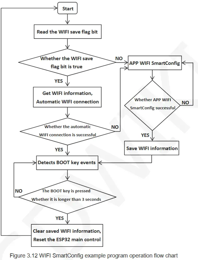
The steps for this example program are as follows:
A. download the EspTouch application on the mobile phone, or copy the installation program “esptouch-v2.0.0.apk” from the folder “7-工具软件 _Tool_software ” in the data package (only Android installation program, IOS application can only be installed from the device), The installer can also be downloaded from the official website.
Download website:
https://www.espressif.com.cn/en/support/download/apps
B. power on the display module, compile and download the sample program, if ESP32 does not save any WIFI information, then directly enter the intelligent distribution mode, at this time, open the EspTouch application on the mobile phone, enter the SSID and password of the WIFI connected to the mobile phone, and then broadcast the relevant information by UDP. Once the ESP32 receives this information, it will connect to the network according to the SSID and password in the information. After the network connection is successful, it will display information such as SSID, password, IP address and MAC address on the display screen and save WIFI information. It should be noted that the success rate of this distribution network is not too high, if it fails, you need to try several times.
C. if the ESP32 has saved WIFI information, it will automatically connect to the network according to the saved WiFi information when it is turned on. If the connection fails, the system enters the intelligent distribution network mode. After the network connection is successful, hold down BOOT for more than 3 seconds, the saved WIFI information will be cleared, and the ESP32 will be reset to perform intelligent network distribution again.
21_WiFi_STA
This example needs to rely on the TFT_eSPI software library, the hardware needs to use the LCD display, ESP32 WIFI module. This sample program shows how the ESP32 connects to WIFI in STA mode according to the SSID and password provided. This example program does the following:
A. Write the WIFI information to be connected in the variables “ssid” and “password” at the beginning of the sample program, as shown below:

B. Power on the display module, compile and download the example program, and you can see that ESP32 starts to connect to WIFI on the display screen. If the WIFI connection is successful, information such as success message, SSID, IP address, and MAC address will be displayed on the display. If the connection lasts longer than 3 minutes, the connection fails, and a failure message is displayed.
22_WiFi_STA_TCP_Client
This example needs to rely on the TFT_eSPI software library, the hardware needs to use the LCD display, ESP32 WIFI module. This example program shows the ESP32 in STA mode, after connecting WIFI, as a TCP client to TCP server process. This example program does the following:
A. At the beginning of the example program “ssid”, “password”, “serverIP”, “serverPort” variables write the required connection WIFI information, TCP serverIP address (computer IP address) and port number, as shown in the following figure:

B. open the “TCP&UDP test tool” or “Network debugging assistant” and other test tools on the computer (installation package in the data package “7-工具软件_Tool_software” directory), create a TCP server in the tool, and the port number should be consistent with the example program Settings.
C. Power on the display module, compile and download the example program, and you can see that ESP32 starts to connect to WIFI on the display screen. If the WIFI connection is successful, information such as the success message, SSID, IP address, MAC address, and TCP server port number is displayed on the display. After the connection is successful, a message is displayed. In this case, you can communicate with the server.
23_WiFi_STA_TCP_Server
This example needs to rely on the TFT_eSPI software library, the hardware needs to use the LCD display, ESP32 WIFI module. This example program shows the ESP32 in STA mode, after connecting to WIFI, as a TCP server by TCP client connection process. This example program does the following:
A. Write the required WIFI information and TCP server port number in the variables “ssid”, “password” and “port” at the beginning of the example program, as shown in the following figure:

B. Power on the display module, compile and download the example program, and you can see that ESP32 starts to connect to WIFI on the display screen. If the WIFI connection is successful, information such as the success message, SSID, IP address, MAC address, and TCP server port number is displayed on the display. Then, the TCP server is created and the TCP client is connected.
C. open the “TCP&UDP test tool” or “Network debugging assistant” and other test tools on the computer (the installation package is in the information package “7-工具软件_Tool_software ” directory), create a TCP client in the tool (pay attention to the IP address and port number should be consistent with the content displayed on the display), and then start to connect the server. If the connection is successful, the corresponding prompt will be displayed, and the server can communicate with it.
24_WiFi_STA_UDP
This example needs to rely on the TFT_eSPI software library, the hardware needs to use the LCD display, ESP32 WIFI module. This example program shows the ESP32 in STA mode, after connecting to WIFI, as a UDP server by the UDP client connection process. This example program does the following:
A. Write the required WIFI information and UDP server port number into the variables “ssid”, “password” and “localUdpPort” at the beginning of the sample program, as shown in the following figure:

B. Power on the display module, compile and download the example program, and you can see that ESP32 starts to connect to WIFI on the display screen. If the WIFI connection is successful, information such as the success message, SSID, IP address, MAC address, and local port number is displayed on the display. Then create a UDP server and wait for the UDP client to connect.
C. open the “TCP&UDP test tool” or “Network debugging assistant” and other test tools on the computer (installation package in the information package “7-工具软件_Tool_software ” directory), create a UDP client in the tool (pay attention to the IP address and port number should be consistent with the content displayed on the display), and then start to connect to the server. If the connection is successful, the corresponding prompt will be displayed, and the server can communicate with it.
25_BLE_scan_V2.0
This example relies on the TFT_eSPI software library and can only use the Arduino-ESP32 core software library version 2.0 (for example, version 2.0.17). Hardware needs to use LCD display, ESP32 Bluetooth module. This example shows the ESP32 Bluetooth module scanning around BLE Bluetooth devices and displaying the name and RSSI of the named BLE Bluetooth device scanned onto the LCD display.
25_BLE_scan_V3.0
This example relies on the TFT_eSPI software library and can only use the Arduino-ESP32 3.0 core software library (for example, version 3.0.3). Hardware needs to use LCD display, ESP32 Bluetooth module. The functionality of this sample program is the same as the 25_BLE_scan_V2.0 sample program.
26_BLE_server_V2.0
This example relies on the TFT_eSPI software library and can only use the Arduino-ESP32 core software library version 2.0 (for example, version 2.0.17). Hardware needs to use LCD display, ESP32 Bluetooth module. This example shows how the ESP32 Bluetooth module creates a Bluetooth BLE server, is connected by a Bluetooth BLE client, and communicates with each other. The steps to use this example are as follows:
A. Install Bluetooth BLE debugging tools on your phone, such as “BLE debugging Assistant”, “LightBlue”, etc.
B. Power on the display module, compile and download the example program, you can see the Bluetooth BLE client running prompt on the display. If you want to change the name of the Bluetooth BLE server device yourself, you can modify it in the “BLEDevice::init” function parameter in the example program, as shown in the following figure:

C. open the Bluetooth on the mobile phone and Bluetooth BLE debugging tool, search the Bluetooth BLE server device name (default is “ESP32_BT_BLE“), and then click the name to connect, after the connection is successful, ESP32 display module will prompt. The next step is Bluetooth communication.
26_BLE_server_V3.0
This example relies on the TFT_eSPI software library and can only use the Arduino-ESP32 3.0 core software library (for example, version 3.0.3). Hardware needs to use LCD display, ESP32 Bluetooth module. This example is the same as the 26_BLE_server_V2.0 example.
27_Desktop_Display
This example program relies on the ArduinoJson, Time, HttpClient, TFT_eSPI, TJpg_Decoder, NTPClient software libraries. Hardware needs to use LCD display, ESP32 WIFI module. This example shows a weather clock desktop that displays city weather conditions (including temperature, humidity, weather ICONS, and scrolling through other weather information), the current time and date, and an astronaut animation. Weather information is obtained from the weather network over the network, and time information is updated from the NTP server. This example program uses the following steps:
A. After opening the example, you must first set the tool ->Partition Scheme to the Huge APP(3MB No OTA /1MB SPIFFS) option, otherwise the compiler will report an error of insufficient memory.
B. write the WIFI information to be connected in the “ssid” and “passwd” variables at the beginning of the sample program, as shown in the following figure. If not set, the intelligent distribution network (for the description of the intelligent distribution network, please refer to the intelligent distribution example program)

Figure 3.17 Setting WIFI information
C. Power on the display module, compile and download the example program, you can see the weather clock desktop on the display screen.
28_display_phonecall
This example relies on the TFT_eSPI software library. The hardware requires an LCD display and a resistive touch screen. This example shows a simple dialing interface for a mobile phone, with content entered at the touch of a button.
29_touch_pen
This example relies on the TFT_eSPI software library. The hardware requires an LCD display and a resistive touch screen. This example shows that by drawing lines on the display, you can check whether the touch screen is functioning properly.
30_RGB_LED_TOUCH_V2.0
This example relies on the TFT_eSPI software library and can only use the Arduino-ESP32 core software library version 2.0 (for example, version 2.0.17). The hardware requires an LCD display, a resistive touch screen, and RGB tri-color lights. This example shows the touch of a button to control RGB light on and off, flicker, and brightness adjustment.
30_RGB_LED_TOUCH_V3.0
This example relies on the TFT_eSPI software library and can only use the Arduino-ESP32 3.0 core software library (for example, version 3.0.3). The hardware requires an LCD display, a resistive touch screen, and RGB tri-color lights. This example shows the same functionality as the 30_RGB_LED_TOUCH_V2.0 test example.
31_LVGL_Demos
This example needs to rely on TFT_eSPI, lvgl software library, hardware needs to use LCD display, resistance touch screen. This example shows the five built-in Demo features of the lvgl embedded UI system. With this example, you can learn how to port the lvgl to the ESP32 platform and how to configure the underlying devices such as the display and touch screen. In the sample program, only one demo can be compiled at a time. Remove the comments of the demo that needs to be compiled, and add comments to other demos, as shown in the following figure:

lv_demo_widgets: Test demos of various widgets
lv_demo_benchmark: Performance benchmark demo
lv_demo_keypad_encoder: Keyboard encoder test demo
lv_demo_music: music player test demo
lv_demo_stress: Stress test demo
Note: This example takes a relatively long time to compile for the first time using Arduino 2.0 lower IED versions, about 15 minutes.
32_WiFi_webserver
This example needs to rely on TFT_eSPI software library, hardware needs to use LCD display, RGB three-color lights. This example shows setting up a web server, and then accessing the web server on the computer, manipulating the icon on the web interface to control the RGB three-color light. The steps to use this example are as follows:
A. Write the WIFI information to be connected in the variables “ssid” and “password” at the beginning of the sample program, as shown below:

B. Power on the display module, compile and download the example program, and you can see that ESP32 starts to connect to WIFI on the display screen. If the WIFI connection is successful, information such as success message, SSID, IP address, and MAC address will be displayed on the display.
C. Enter the IP address shown in the above steps in the browser URL input field on the computer. At this time, you can access the web interface and click the corresponding icon on the interface to control the RGB three-color light.
Touch_calibrate
This program relies on the TFT_eSPI software library, which is specially designed for the calibration of resistive touch screens, and the calibration steps are as follows:
A. Open the calibration program and set the display direction of the display screen, as shown below. Because the calibration program is calibrated according to the display direction, this setting must be consistent with the actual display direction.

B. Power on the display module, compile and download the example program, you can see the calibration interface on the display screen, then click the four corners according to the arrow prompt.
C. After the calibration is completed, the calibration result is output through the serial port, as shown in the following figure. At the same time, the calibration detection interface is entered, and the calibration detection interface is tested by drawing dots and lines.

D. After the calibration result is accurate, copy the calibration parameters of the serial port to the example program used.
Documents / Resources
 |
LCDWIKI E32N40T 4.0 Inch Arduino Demo [pdf] Instructions E32R40T, E32N40T, E32N40T 4.0 Inch Arduino Demo, 4.0 Inch Arduino Demo, Arduino Demo |