LCDWIKI E32N40T 4.0英寸Arduino演示说明

软硬件平台说明
模块: 4.0-inch ESP32-32E display module with 320×480 resolution and ST7796 screen driver IC.
Module master: ESP32-WROOM-32E module, the highest main frequency 240MHz, support 2.4G WIFI+ Bluetooth.
Arduino IED versions: versions 1.8.19 and 2.3.2.
ESP32 Ardunio core library software versions: 2.0.17 and 3.0.3.
引脚分配说明

4.0寸ESP32显示模组主控制器为ESP32-32E,其板载外设GPIO分配如下表所示:


表 2.1 ESP32-32E 板载外设管脚分配说明
使用说明amp程序
设置 ESP32 Arduino 开发环境
For detailed instructions on setting up the ESP32 Arduino development environment, please refer to the documentation in the package titled ”
Arduino_IDE1_development_environment_construction_for_ESP32″ and ” Arduino_IDE2_development_environment_construction_for_ESP32″.
安装第三方软件库
开发环境搭建完成后,第一步是安装系统用到的第三方软件库。amp程序。步骤如下:
A、打开 “1-示例程序_Demo \Arduino\Install libraries” directory in the package and find the third-party software library, as shown in the following figure:

ArduinoJson: C++JSON software library for Arduino and the Internet of Things.
ESP32-audioI2S: ESP32’s audio decoding software library uses ESP32’s I2S bus to play audio file通过外部音频设备从 SD 卡播放 mp3、m4a 和 mav 等格式的音乐。
ESP32Time: Arduino software library for setting and retrieving internal RTC time on ESP32 board
HttpClient: An HTTP client software library that interacts with Arduino’s web 服务器。
Lvgl: A highly customizable, low resource consuming, aesthetically pleasing, and easy-to-use embedded system graphics software library.
NTP客户端: Connect NTP client software library to NTP server.
TFT_eSPI: The Arduino graphics library for TFT-LCD LCD screens supports multiple platforms and LCD driver ICs.
时间: A software library that provides timing functionality for Arduino.
TJpg_Decoder: The Arduino platform JPG format image decoding library can decode JPG file从 SD 卡或闪存中读取并显示在 LCD 上。
XT_DAC_Audio: The ESP32 XTronic DAC audio software library supports WAV format audio files.
B. Copy these software libraries to the library directory of the project folder. The library directory of the project folder defaults to “C:\Users\行政人员\Documents\Arduino\libraries” (the red part represents the actual username of the computer). If the project folder path is modified, it needs to be copied to the modified project folder library directory.
C. After the installation of the third-party software library is completed, you can open the samp程序使用说明。
lvgl 和 TFT_eSPI 软件库在第三方软件库中使用前需要进行配置,软件包中的软件库已经配置好,可以直接使用,如果不想使用已经配置好的库,可以从 GitHub 下载最新版本的库,重新配置,步骤如下:
A.在GitHub上找到下载链接并下载,下载链接如下:
lvgl: https://github.com/lvgl/lvgl/tree/release/v8.3(Only V8. x version can be used, V9. x version cannot be used)
TFT_eSPI: https://github.com/Bodmer/TFT_eSPI
附件是其他不需要配置的软件包的下载链接:
ArduinoJson: https://github.com/bblanchon/ArduinoJson.git
ESP32时间: https://github.com/fbiego/ESP32Time
Http客户端: http://github.com/amcewen/HttpClient
NTP客户端: https://github.com/arduino-libraries/NTPClient.git
时间: https://github.com/PaulStoffregen/Time
TJpg_解码器: https://github.com/Bodmer/TJpg_Decoder
B. After the library download is complete, unzip it (for ease of distinction, the decompressed library folder can be renamed), and then copy it to the project folder library directory (default is “C:\Users\行政人员\Documents\Arduino \ libraries” (the red part is the actual user name of the computer). Next, perform library configuration by opening the “1-示例程序_Demo \Arduino\Replaced files” directory in the package and finding the replacement file,如下图所示:

C.配置LVGL库:
复制 lv_conf. h file 从替换 files目录移动到项目库目录中lvgl库的顶层目录下,如下图:

打开 lv_conf_internal. h file 在 源码 directory of the lvgl library under the engineering library directory, as shown in the following figure:

打开后 file, modify the contents of line 41 as shown below (by “.. /.. /lv_conf.h Change the value to.. /lv_conf.h “), and save the modification.

复制 examp莱斯 和 演示 from lvgl in the project library to 源码 in lvgl, as shown below:

复制目录状态:

D.配置TFT_eSPI库:
Firstly, rename the User_Setup. h file in the top-level directory of the TFT_eSPI library under the project folder library directory to User_Setup_bak. h.
Then, copy the User_Setup. h file 从替换 files目录复制到项目库目录下的TFT_eSPI库的顶层目录中,如下图所示:

Next, rename ST7796_ Init. h in the TFT_eSPI library TFT_Drivers directory under the project folder directory to ST7796_ Init. bak. h, and then copy ST7796_ Init. h in the Replaced files directory to the TFD_eSPI library TFT_Drivers directory under the project folder library directory, as shown in the following figure:

Example 程序使用说明
前任ample program is located in the “1-示例程序_Demo \Arduino\demos” directory of the package, as shown in the following figure:

各ex的介绍amp程序如下:
01_简单测试
这个前任ample 是一个基本的 examp不依赖任何第三方库的程序。硬件需要LCD显示屏,显示全屏颜色填充和随机矩形填充。本例amp可以直接用它来检查显示屏是否正常运行。
02_colligate_test
这个前任ample依赖TFT_eSPI软件库,硬件需要LCD显示屏,显示内容包括画点、线、各种图形显示、运行时间统计等,是一款综合性的显示工具amp勒。
03_显示图形
这个前任ample依赖TFT_eSPI软件库,硬件需要LCD显示屏,显示内容包括各种图形绘制、填充。
04_显示_滚动
这个前任ample需要TFT_eSPI软件库,硬件需为LCD显示屏,显示内容包括汉字及图像、滚动文字显示、反色显示、四个方向旋转显示。
05_显示_SD_jpg_图片
这个前任amp需要依赖TFT_eSPI和TJpg_Secoder软件库,硬件需要LCD显示屏和MicroSD卡。本例amp函数功能是从 MicroSD 卡读取 JPG 图片,解析图片,然后在 LCD 上显示。示例amp使用步骤为:
A. Copy the JPG images from the “PIC_320x480” directory in the samp通过电脑将.le文件夹复制到MicroSD卡的根目录。
B.将MicroSD卡插入显示模块的SD卡槽;
C.显示模块上电,编译并下载程序ample程序,您将看到LCD屏幕上交替显示图片。
06_RGB_LED_V2.0
这个前任ample不依赖任何第三方软件库,只能使用Arduino-ESP32核心软件库2.0版本(如2.0.17版本)。硬件需要RGB三色灯。本例ample展示了RGB三色灯的开关控制、闪烁控制、以及PWM亮度控制。
06_RGB_LED_V3.0
这个前任ample 不依赖任何第三方软件库,只能使用 Arduino-ESP32 的 3.0 核心软件库(例如 3.0.3)。所需的硬件和功能与 ex 中所示的相同ample 06_RGB_LED_V2.0。
07_Flash_DMA_jpg
这个前任ample 依赖于 TFT_eSPI 和 TJpg_Decoder 软件库。硬件需要 LCD 显示器。此 examp示例代码展示了从 ESP32 模块内部的 Flash 中读取 JPG 图片并解析数据,然后在 LCD 上显示图片的过程。amp使用步骤:
A.通过在线模具工具获取需要显示的jpg图片。在线模具工具 web地点:
http://tomeko.net/online_tools/file_to_hex.php?lang=en
B. after the success of the module, copy the data to the array of the “image.h” file 在ample 文件夹(可以重命名该阵列,并且amp程序也应该同步修改)
C.给显示模块上电,编译并下载程序ample程序,可以在LCD屏幕上看到图片显示。
08_key_test
这个前任ample不依赖任何第三方软件库,硬件需要使用BOOT按钮和RGB三色灯,本例ample表示以轮询的方式检测按键事件,同时操作按键来控制RGB三色灯。
09_键_中断
这个前任ample不依赖任何第三方软件库,硬件需要使用BOOT按钮和RGB三色灯,本例ample表示采用中断方式检测按键事件,同时操作按键来控制RGB三色灯的亮与灭。
10_uart
这个前任ample 依赖于 TFT_eSPI 软件库,硬件需要串口和 LCD 显示器。本例amp图为ESP32通过串口与PC交互的方式,ESP32通过串口向电脑发送信息,电脑通过串口向ESP32发送信息,ESP32接收到信息后,显示在LCD屏幕上。
11_RTC_test
这个前任ample 依赖于 TFT_eSPI 和 ESP32Time 软件库,硬件需要 LCD 显示屏。本示例amp图为使用ESP32的RTC模块设置实时时间和日期,并在LCD显示屏上显示时间和日期。
12_timer_test_V2.0
这个前任ample不依赖任何第三方软件库,只能使用Arduino-ESP32核心软件库2.0版本(如2.0.17版本)。硬件需要RGB三色灯。本例amp图为ESP32定时器的使用,通过设置1秒的定时时间来控制绿色LED灯熄灭(每隔1秒亮,每隔1秒灭,一直循环)。
12_timer_test_V3.0
这个前任ample不依赖任何第三方软件库,只能使用Arduino-ESP32的3.0核心软件库(例如3.0.3)。硬件需要RGB三色灯。此example 演示了与 12_timer_test_V2.0 ex 相同的功能amp勒。
13_获取电池电量tage
这个前任ample 依赖于 TFT_eSPI 软件库。硬件需要 LCD 显示屏和 3.7V 锂电池。此示例amp图为使用ESP32的ADC功能获取voltag外部锂电池的电量并显示在LCD显示屏上。
14_背光_PWM_V2.0
这个前任ample 依赖于 TFT_eSPI 软件库,只能使用 Arduino-ESP32 核心软件库版本 2.0(例如ample,版本 2.0.17)。硬件需要 LCD 显示屏和电阻式触摸屏。此示例amp图为通过显示模块的触摸滑动操作,可以调整显示屏的背光亮度,同时亮度值也会发生变化。
14_Backlight_PWM_V3.O
这个前任ample 依赖于 TFT_eSPI 软件库,只能使用 Arduino-ESP32 3.0 核心软件库(例如ample,版本 3.0.3)。硬件需要 LCD 显示屏和电阻式触摸屏。此示例ample 显示与 14_Backlight_PWM_V2.0 ex 相同的功能amp勒。
这个前任amp本例依赖 TFT_eSPI、TJpg_Decoder、ESP32-audioI2S 软件库,只能使用 Arduino-ESP32 核心软件库 2.0 版本(如 2.0.17 版本),硬件需要 LCD 显示屏、电阻式触摸屏、扬声器和 MicroSD 卡。本例ample 显示正在读取 mp3 音频 file 从 SD 卡,显示 file 名称显示在 LCD 上,并循环播放。显示屏上有两个触摸按钮图标,操作一个可以控制音频暂停和播放,操作另一个可以控制静音和播放声音。以下是示例amp乐:
A. 复制所有 mp3 音频 file位于 s 中的“mp3”目录中ample 文件夹复制到 MicroSD 卡。当然,您也可以不使用音频 file在这个目录中,找到一些 mp3 音频 files,值得注意的是,example程序最多只能循环播放10首mp3歌曲。
B.将MicroSD卡插入显示模块的SD卡槽;
C.给显示模块上电,编译并下载程序ample程序,可以看到液晶屏上显示歌曲名称,外接扬声器播放声音,触摸操作屏幕上的按钮图标,可以控制音频播放。
16_音频_WAV_V2.0
这个前任ample 依赖于 XT_DAC_Audio 软件库,只能使用 Arduino-ESP32 核心软件库版本 2.0(例如ample,版本 2.0.17)。硬件需要扬声器。此示例ample 节目正在播放音频 file 使用 ESP32 录制 wav 格式的视频。使用此示例的步骤ample如下:
A. 编辑音频 file that needs to be played, copy the generated audio data to the array of the “Audio_data.h” file 在ample 文件夹(可以重命名该阵列,并且amp程序也应同步)。请注意,编辑后的音频 file 不能太大,否则会超出 ESP32 模块内部 Flash 的容量。这意味着编辑音频的长度 file,ampling rate and the number of channels. Here is an audio editing software called 大胆, which you can download from the Internet
B.给显示模块上电,编译并下载程序ample 程序,您可以听到扬声器播放音频。
17_Buzzer_PiratesOfTheCaribian
这个前任ample 不依赖任何第三方软件库,硬件需要扬声器。此 examp图为利用不同的频率上下拉动销钉,模拟声振动,使喇叭发声。
18_WiFi_扫描
这个前任amp该文件依赖于 TFT_eSPI 软件库,硬件需要 LCD 显示屏和 ESP32 WIFI 模块。该文件amp图为ESP32 WIFI模块在STA模式下扫描周边无线网络信息,扫描到的无线网络信息显示在LCD显示屏上,无线网络信息包括SSID、RSSI、CHANNEL、ENC_TYPE等,扫描到无线网络信息后,系统会显示扫描到的无线网络数量,最多显示前17个扫描到的无线网络。
19_WiFi_AP
这个前任amp该文件依赖于 TFT_eSPI 软件库,硬件需要 LCD 显示屏和 ESP32 WIFI 模块。该文件amp该文件显示了ESP32 WIFI模块设置为AP模式,用于WIFI终端连接。显示屏将显示ESP32 WIFI模块设置为AP模式的SSID、密码、主机IP地址、主机MAC地址等信息。一旦有终端连接成功,显示屏将显示终端连接的数量。请在文件开头的“SSID”和“Password”变量中设置自己的ssid和密码ample程序,如下图:

20_WiFi_SmartConfig
这个前任amp该文件依赖于TFT_eSPI软件库,硬件需要LCD显示屏、ESP32 WIFI模块和BOOT按钮。该文件amp图为ESP32 WIFI模块在STA模式下,通过EspTouch手机APP进行智能配网流程。整个流程amp程序运行流程图如下:
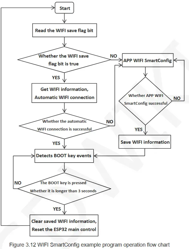
此示例的步骤amp程序如下:
A. download the EspTouch application on the mobile phone, or copy the installation program “esptouch-v2.0.0.apk” from the folder “7-工具软件 _Tool_software ” in the data package (only Android installation program, IOS application can only be installed from the device), The installer can also be downloaded from the official web地点。
下载 web地点:
https://www.espressif.com.cn/en/support/download/apps
B. power on the display module, compile and download the sample程序中,如果ESP32没有保存任何WIFI信息,那么直接进入智能配网模式,此时在手机上打开EspTouch应用程序,输入手机连接的WIFI的SSID和密码,然后以UDP的方式广播相关信息。ESP32一旦收到此信息,就会根据信息中的SSID和密码进行连接。网络连接成功后会在显示屏上显示SSID、密码、IP地址和MAC地址等信息并保存WIFI信息。需要注意的是,这种配网成功率不是太高,如果失败的话,需要多试几次。
C. if the ESP32 has saved WIFI information, it will automatically connect to the network according to the saved WiFi information when it is turned on. If the connection fails, the system enters the intelligent distribution network mode. After the network connection is successful, hold down BOOT for more than 3 seconds, the saved WIFI information will be cleared, and the ESP32 will be reset to perform intelligent network distribution again.
21_WiFi_STA
这个前任amp需要依赖TFT_eSPI软件库,硬件需要用到LCD显示屏、ESP32 WIFI模块。本例amp程序展示了 ESP32 如何根据提供的 SSID 和密码以 STA 模式连接 WIFI。此示例amp程序执行以下操作:
A. Write the WIFI information to be connected in the variables “服务名称“ 和 ”密码” at the beginning of the sample程序,如下图:

B.给显示模块上电,编译并下载程序ample 程序,在显示屏上可以看到 ESP32 开始连接 WIFI。如果 WIFI 连接成功,显示屏上会显示成功信息、SSID、IP 地址、MAC 地址等信息。如果连接时间超过 3 分钟,则连接失败,显示失败信息。
22_WiFi_STA_TCP_Client
这个前任amp需要依赖TFT_eSPI软件库,硬件需要使用LCD显示屏,ESP32 WIFI模块。本例amp程序展示了 ESP32 在 STA 模式下,连接 WIFI 后,作为 TCP 客户端到 TCP 服务器的过程。此示例amp程序执行以下操作:
A. 在ex的开始amp程序中的“ssid”、“password”、“serverIP”、“serverPort”变量写入需要连接的WIFI信息、TCP serverIP地址(电脑IP地址)和端口号,如下图所示:

B. open the “TCP&UDP test tool” or “Network debugging assistant” and other test tools on the computer (installation package in the data package “7-工具软件_Tool_software” directory), create a TCP server in the tool, and the port number should be consistent with the examp程序设置。
C.给显示模块上电,编译并下载程序ample 程序,在显示屏上可以看到 ESP32 开始连接 WIFI,如果 WIFI 连接成功,显示屏上会显示成功信息、SSID、IP 地址、MAC 地址、TCP 服务器端口号等信息,连接成功后会显示一条信息,此时就可以与服务器进行通信了。
23_WiFi_STA_TCP_Server
这个前任amp需要依赖TFT_eSPI软件库,硬件需要使用LCD显示屏,ESP32 WIFI模块。本例amp程序展示了ESP32在STA模式下,连接WIFI后,作为TCP服务器通过TCP客户端连接的过程。本例amp程序执行以下操作:
A. Write the required WIFI information and TCP server port number in the variables “ssid”, “password” and “port” at the beginning of the example程序,如下图所示:

B.给显示模块上电,编译并下载程序amp运行程序,在显示屏上可以看到ESP32开始连接WIFI,如果WIFI连接成功,显示屏上会显示成功信息、SSID、IP地址、MAC地址、TCP服务器端口号等信息,然后会创建TCP服务器,并连接TCP客户端。
C. open the “TCP&UDP test tool“ 或者 ”Network debugging assistant” and other test tools on the computer (the installation package is in the information package “7-工具软件_Tool_software ” directory), create a TCP client in the tool (pay attention to the IP address and port number should be consistent with the content displayed on the display), and then start to connect the server. If the connection is successful, the corresponding prompt will be displayed, and the server can communicate with it.
24_WiFi_STA_UDP
这个前任amp需要依赖TFT_eSPI软件库,硬件需要使用LCD显示屏,ESP32 WIFI模块。本例amp程序展示了ESP32在STA模式下,连接WIFI后,作为UDP服务器由UDP客户端连接的过程。本例amp程序执行以下操作:
A. Write the required WIFI information and UDP server port number into the variables “ssid”, “password” and “localUdpPort” at the beginning of the sample程序,如下图所示:

B.给显示模块上电,编译并下载程序ample 程序,在显示屏上可以看到 ESP32 开始连接 WIFI。如果 WIFI 连接成功,显示屏上会显示成功信息、SSID、IP 地址、MAC 地址、本地端口号等信息。然后创建 UDP 服务器,等待 UDP 客户端连接。
C. open the “TCP&UDP test tool” or “Network debugging assistant” and other test tools on the computer (installation package in the information package “7-工具软件_Tool_software ” directory), create a UDP client in the tool (pay attention to the IP address and port number should be consistent with the content displayed on the display), and then start to connect to the server. If the connection is successful, the corresponding prompt will be displayed, and the server can communicate with it.
25_BLE_scan_V2.0
这个前任ample 依赖于 TFT_eSPI 软件库,只能使用 Arduino-ESP32 核心软件库版本 2.0(例如ample,版本 2.0.17)。硬件需要使用 LCD 显示屏、ESP32 蓝牙模块。本例amp图为 ESP32 蓝牙模块扫描周围的 BLE 蓝牙设备,并将扫描到的命名 BLE 蓝牙设备的名称和 RSSI 显示到 LCD 显示屏上。
25_BLE_scan_V3.0
这个前任ample 依赖于 TFT_eSPI 软件库,只能使用 Arduino-ESP32 3.0 核心软件库(例如ample,版本 3.0.3)。硬件需要使用 LCD 显示屏、ESP32 蓝牙模块。此 s 的功能amp程序与25_BLE_scan_V2.0相同amp乐程序。
26_BLE_server_V2.0
这个前任ample 依赖于 TFT_eSPI 软件库,只能使用 Arduino-ESP32 核心软件库版本 2.0(例如ample,版本 2.0.17)。硬件需要使用 LCD 显示屏、ESP32 蓝牙模块。本例amp该文件展示了 ESP32 蓝牙模块如何创建蓝牙 BLE 服务器,如何通过蓝牙 BLE 客户端进行连接,以及如何相互通信。使用该文件的步骤如下:ample如下:
A.在手机上安装蓝牙BLE调试工具,例如“BLE调试助手”、“LightBlue”等。
B.给显示模块上电,编译并下载程序ample program, you can see the Bluetooth BLE client running prompt on the display. If you want to change the name of the Bluetooth BLE server device yourself, you can modify it in the “BLEDevice::init” function parameter in the example程序,如下图所示:

C. open the Bluetooth on the mobile phone and Bluetooth BLE debugging tool, search the Bluetooth BLE server device name (default is “ESP32_BT_BLE“), and then click the name to connect, after the connection is successful, ESP32 display module will prompt. The next step is Bluetooth communication.
26_BLE_server_V3.0
这个前任ample 依赖于 TFT_eSPI 软件库,只能使用 Arduino-ESP32 3.0 核心软件库(例如ample,版本 3.0.3)。硬件需要使用 LCD 显示屏、ESP32 蓝牙模块。本例ample 与 26_BLE_server_V2.0 ex 相同amp勒。
27_Desktop_Display
这个前任amp程序依赖ArduinoJson、Time、HttpClient、TFT_eSPI、TJpg_Decoder、NTPClient软件库。硬件需要使用LCD显示屏、ESP32 WIFI模块。本例ample 显示了天气时钟桌面,其中显示城市天气状况(包括温度、湿度、天气图标以及滚动浏览其他天气信息)、当前时间和日期以及宇航员动画。天气信息通过网络从天气网络获取,时间信息从 NTP 服务器更新。此示例amp程序采用以下步骤:
A. 打开ex后ample, you must first set the tool ->Partition Scheme 到 Huge APP(3MB No OTA /1MB SPIFFS) option, otherwise the compiler will report an error of insufficient memory.
B.在s开头的“ssid”和“passwd”变量中写入要连接的WIFI信息amp程序,如下图所示。若不设置,则智能配电网(智能配电网的描述请参考智能配电网示例)amp程序)

图3.17 设置WIFI信息
C.给显示模块上电,编译并下载程序amp程序后,您可以在显示屏上看到天气时钟桌面。
28_显示_电话
这个前任ample 依赖于 TFT_eSPI 软件库。硬件需要 LCD 显示屏和电阻式触摸屏。此 example展示了一个简单的手机拨号界面,只需按一下按钮就可以输入内容。
29_触摸笔
这个前任ample 依赖于 TFT_eSPI 软件库。硬件需要 LCD 显示屏和电阻式触摸屏。此 examp如图所示,通过在显示屏上画线,可以检查触摸屏是否正常工作。
30_RGB_LED_触摸_V2.0
这个前任ample 依赖于 TFT_eSPI 软件库,只能使用 Arduino-ESP32 核心软件库版本 2.0(例如ample,版本 2.0.17)。硬件需要 LCD 显示屏、电阻式触摸屏和 RGB 三色灯。此示例ample 显示触摸按钮来控制 RGB 灯的开启和关闭、闪烁和亮度调节。
30_RGB_LED_触摸_V3.0
这个前任ample 依赖于 TFT_eSPI 软件库,只能使用 Arduino-ESP32 3.0 核心软件库(例如ample,版本 3.0.3)。硬件需要 LCD 显示屏、电阻式触摸屏和 RGB 三色灯。此示例ample 显示与 30_RGB_LED_TOUCH_V2.0 测试示例相同的功能amp勒。
31_LVGL_演示
这个前任amp需要依赖TFT_eSPI、lvgl软件库,硬件需要使用LCD显示屏、电阻触摸屏。本例ample 展示了 lvgl 嵌入式 UI 系统的五个内置 Demo 功能。通过此示例amp在本教程中,你将了解如何将 lvgl 移植到 ESP32 平台,以及如何配置显示屏、触摸屏等底层设备。ample程序,每次只能编译一个demo,将需要编译的demo的注释去掉,其他demo添加注释,如下图:

lv_demo_widgets:各种小部件的测试演示
lv_demo_benchmark:性能基准测试演示
lv_demo_keypad_encoder:键盘编码器测试演示
lv_demo_music:音乐播放器测试演示
lv_demo_stress:压力测试演示
笔记: 这个前任ample takes a relatively long time to compile for the first time using Arduino 2.0 lower IED versions, about 15 minutes.
32_WiFi_web服务器
这个前任amp需要依赖TFT_eSPI软件库,硬件需要用到LCD显示屏,RGB三色灯。本例ample 展示了如何设置 web 服务器,然后访问 web 服务器上,操作图标 web 接口来控制RGB三色灯。使用本例的步骤如下:ample如下:
A.在s开头的变量“ssid”和“password”中写入需要连接的WIFI信息ample程序,如下图:

B.给显示模块上电,编译并下载程序ample 程序,在显示屏上可以看到 ESP32 开始连接 WIFI,如果 WIFI 连接成功,显示屏上会显示成功信息、SSID、IP 地址、MAC 地址等信息。
C. Enter the IP address shown in the above steps in the browser URL 输入框。此时,您可以访问 web 界面,点击界面上对应的图标,即可控制RGB三色灯。
触摸校准
本程序依赖TFT_eSPI软件库,该软件库专门针对电阻式触摸屏的校准而设计,校准步骤如下:
A. Open the calibration program and set the display direction of the display screen, as shown below. Because the calibration program is calibrated according to the display direction, this setting must be consistent with the actual display direction.

B.给显示模块上电,编译并下载程序ample程序,在显示屏上可以看到校准界面,然后根据箭头提示点击四个角。
C、校准完成后,通过串口输出校准结果,如下图所示。同时进入校准检测界面,通过画点画线的方式对校准检测界面进行测试。

D.校准结果准确后,将串口校准参数复制到examp使用的程序。
文件/资源
 |
LCDWIKI E32N40T 4.0英寸Arduino演示 [pdf] 指示 E32R40T、E32N40T、E32N40T 4.0 英寸 Arduino 演示板、4.0 英寸 Arduino 演示板、Arduino 演示板 |