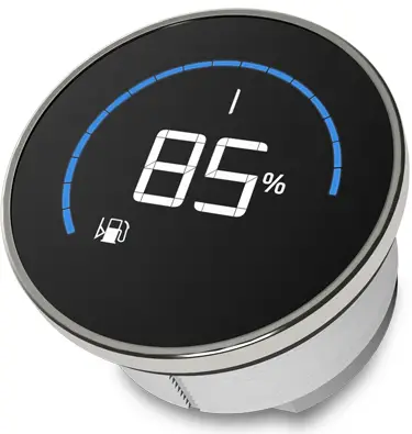
veratron VMH FLEX 1.4 Inch Colour Multi-Function Display
Product Information
Specifications
- Product Series: VMH Series
- Model: VMH Flex
- User Manual Revision: AA
Introduction
- Part Number: B00186401 or B00127801
Description:
- 1x VMH Flex – J1939 or 1x Wiring Harness – J1939
- 1x 52 mm Spinlock Nut
- 1x Rubber Sealing Gasket
- 1x Safety Instructions and Veratron Card
Description
- The VMH Flex is a versatile instrument capable of reading data from sensors and CAN networks.
- It features LIN connectivity for accessing battery information via the Intelligent Battery Sensor.
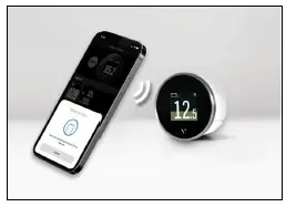
Contactless Configuration
- The VMH Flex offers contactless configuration, allowing users to set up the instrument using a smartphone app.
- Simply define settings on the app and transfer them by holding the smartphone near the VMH Flex.
- The built-in passive antenna enables configuration without requiring a power supply.
Variants
- Part Number: B00186401
- Version: VMH Flex – NMEA 2000
Product Usage Instructions
Safety During Installation
- Ensure all safety precautions are followed during the installation process to prevent accidents or damage.
Safety After Installation
- After installation, verify that all connections are secure and there are no exposed wires to ensure safe operation.
Electrical Connection
- Follow the electrical connection guidelines provided in the manual to correctly connect the VMH Flex to power sources.
FAQ
Q: How can I configure the VMH Flex?
A: You can configure the VMH Flex using the contactless configuration feature by following the instructions in the user manual.
INTRODUCTION
PACKAGE CONTENTS

DESCRIPTION
- Small but powerful, the VMH Flex is the perfect compromise to display a large amount of boat data in a compact device.
- The innovative laser touch button allows you to scroll up to 5 different screens, no matter if you are wearing gloves or it’s raining on your deck.
- Every screen can be freely customized with your most important information, and the setup – including alarms – is easily done with your smartphone just with a “tab”.
- Capable of reading from both sensors and CAN networks, the VMH Flex is further empowered by the LIN connectivity to get all the information from your battery thanks to the Intelligent Battery Sensor.
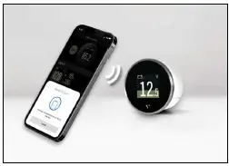
CONTACTLESS CONFIGURATION
- Thanks to contactless configuration, you can configure your all-in-one instrument with a simple “tap.
- Start the smartphone app and define your settings via the user-friendly interface. Then simply hold your smartphone onto the VMH Flex to transfer the configuration immediately.
- Thanks to the built-in passive antenna, the configuration can be done without a power supply!
VARIANTS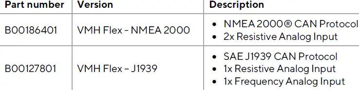
SAFETY INFORMATION
- WARNING: No smoking! No open fire or heat sources!
- The product was developed, manufactured, and inspected according to the basic safety requirements of EC Guidelines and state-of-the-art technology.
- The instrument is designed for use in grounded vehicles and machines as well as in pleasure boats, including non-classified commercial shipping.
- Use our product only as intended. Use of the product for reasons other than its intended use may lead to personal injury, property damage, or environmental damage.
- Before installation, check the vehicle documentation for vehicle type and any possible special features!
- Use the assembly plan to learn the location of the fuel/hydraulic/compressed air and electrical lines!
- Note possible modifications to the vehicle, which must be considered during installation!
- To prevent personal injury, property damage, or environmental damage, basic knowledge of motor vehicle/shipbuilding electronics and mechanics is required.
- Make sure that the engine cannot start unintentionally during installation!
- Modifications or manipulations to veratron products can affect safety. Consequently, you may not modify or manipulate the product!
- When removing/installing seats, covers, etc., ensure that lines are not damaged and plug-in connections are not loosened!
- Not all data from other installed instruments with volatile electronic memories.
SAFETY DURING INSTALLATION
- During installation, ensure that the product’s components do not affect or limit vehicle functions. Avoid damaging these components!
- Only install undamaged parts in a vehicle!
- During installation, ensure that the product does not impair the field of vision and that it cannot impact the driver’s or passenger’s head!
- A specialized technician should install the product. If you install the product yourself, wear appropriate work clothing. Do not wear loose clothing, as it may get caught in moving parts. Protect long hair with a hair net.
- When working on the onboard electronics, do not wear metallic or conductive jewelry such as necklaces, bracelets, rings, etc.
- If work on a running engine is required, exercise extreme caution. Wear only appropriate work clothing as you are at risk of personal injury, resulting from being crushed or burned.
- Before beginning, disconnect the negative terminal on the battery, otherwise, you risk a short circuit. If the vehicle is supplied with auxiliary batteries, you must also disconnect the negative terminals on these batteries!
- Short circuits can cause fires, battery explosions, and damage to other electronic systems. Please note that when you disconnect the battery, all volatile electronic memories lose their input values and must be reprogrammed.
- If working on gasoline boat motors, let the motor compartment fan run before beginning work.
- Pay attention to how lines and cable harnesses are laid so that you do not drill or saw through them!
- Do not install the product in the mechanical and electrical airbag area!
- Do not drill holes or ports in load-bearing or stabilizing stays or tie bars!
- When working underneath the vehicle, secure it according to the specifications of the vehicle manufacturer.
- Note the necessary clearance behind the drill hole or port at the installation location.
- Required mounting depth: 65 mm.
- Drill small ports; enlarge and complete them, if necessary, using taper milling tools, saber saws, keyhole saws, or files. Deburr edges. Follow the safety instructions of the tool manufacturer.
- Use only insulated tools if work is necessary on live parts.
- Use only the multimeter or diode test lamps provided, to measure voltages and currents in the vehicle/machine or boat. The use of conventional test lamps can cause damage to control units or other electronic systems.
- The electrical indicator outputs and cables connected to them must be protected from direct contact and damage. The cables in use must have enough insulation and electric strength and the contact points must be safe from touch.
- Use appropriate measures to also protect the electrically conductive parts of the connected consumer from direct contact. Laying metallic, uninsulated cables and contacts is prohibited.
SAFETY AFTER INSTALLATION
- Connect the ground cable tightly to the negative terminal of the battery.
- Reenter/reprogram the volatile electronic memory values.
- Check all functions.
- Use only clean water to clean the components. Note the Ingress Protection (IP) ratings (IEC 60529).
ELECTRICAL CONNECTION
- Note cable cross-sectional area!
- Reducing the cable cross-sectional area leads to higher current density, which can cause the cable cross-sectional area in question to heat up!
- When installing electrical cables, use the provided cable ducts and harnesses; however, do not run cables parallel to ignition cables or to cables that lead to large electricity consumers.
- Fasten cables with cable ties or adhesive tape. Do not run cables over moving parts. Do not attach cables to the steering column!
- Ensure that cables are not subject to tensile, compressive, or shearing forces.
- If cables are run through drill holes, protect them using rubber sleeves or the like.
- Use only one cable stripper to strip the cable. Adjust the stripper so that stranded wires are not damaged or separated.
- Use only a soft soldering process or commercially available crimp connector to solder new cable connections!
- Make crimp connections with cable crimping pliers only. Follow the safety instructions of the tool manufacturer.
- Insulate exposed stranded wires to prevent short circuits.
- Caution: Risk of short circuit if junctions are faulty or cables are damaged.
- Short circuits in the vehicle network can cause fires, battery explosions, and damage to other electronic systems. Consequently, all power supply cable connections must be provided with weldable connectors and be sufficiently insulated.
- Ensure ground connections are sound.
- Faulty connections can cause short circuits. Only connect cables according to the electrical wiring diagram.
- If operating the instrument on power supply units, note that the power supply unit must be stabilized and it must comply with the following standard: DIN EN 61000, Parts 6-1 to 6-4.
INSTALLATION
- WARNING: Do not drill holes and installation openings in load-bearing or stabilizing struts or spars!
- For the installation location, ensure the necessary clearance behind the holes or the installation opening. The required installation depth is 65 mm.
- Pre-drill small installation openings, enlarge with cone cutter, hole saw, jigsaw, or file if necessary, and finish. Deburr edges. Refer to the safety instructions of the hand tool manufacturer.
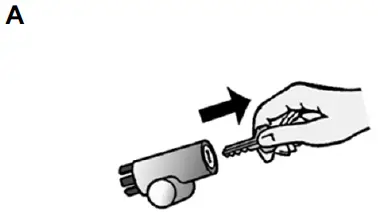
BEFORE THE ASSEMBLY
- A: Before beginning, turn off the ignition and remove the ignition key. If necessary, interrupt the main circuit switch.
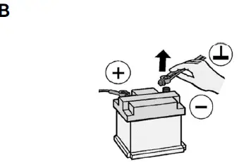
- B: Disconnect the negative terminal on the battery. Make sure the battery can not restart unintentionally.
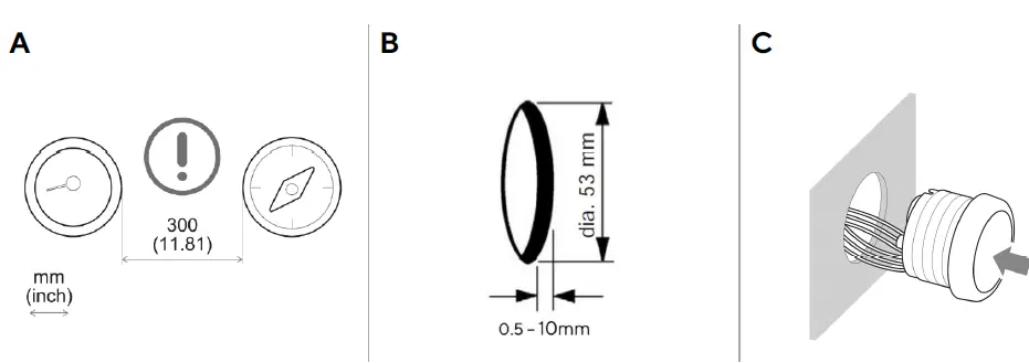
MOUNTING WITH SPINLOCK NUT
- Place the device at least 300 mm away from any magnetic compass. [A]
- Make a round hole, considering the external dimensions of the device. [B]
- The panel thickness can be in the range of 0-10mm.
- Remove the spinlock nut and insert the device from the front. [C]
- Feed the cables through the spinlock nut and carefully screw it in at least two turns.
- Connect the plugs.
CONNECTIONS
- Before beginning, disconnect the negative terminal on the battery, otherwise, you risk a short circuit.
- If the vehicle is supplied with auxiliary batteries, you must also disconnect the negative terminals on these batteries! Short circuits can cause fires, battery explosions, and damage to other electronic systems.
- Please note that when you disconnect the battery, all volatile electronic memories lose their input values and must be reprogrammed.
PINOUT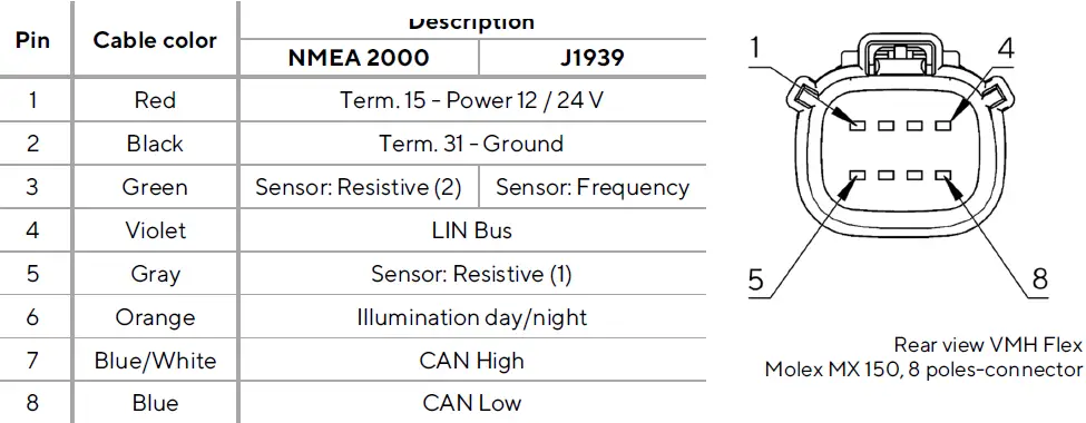
ELECTRICAL SCHEMATIC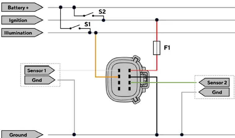
Designations in the circuit diagram:
- S1 – Day/Night Mode switch (not included)
- S2 – Ignition Key
- F1 – Fuse (not included)
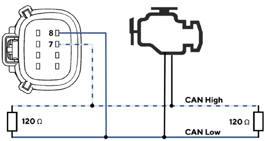
CONNECTION TO THE SAE J1939 NETWORK
- The VMH Flex J1939 cable does not include a connector on the CAN wires to fit the different engine manufacturers.
- Connect pin 8 (blue wire) to the CAN Low- and pin 7 (blue/white wire) to the CAN High signal.
- The data lines must be terminated by resistors as shown in the schematic.
CONNECTING THE IBS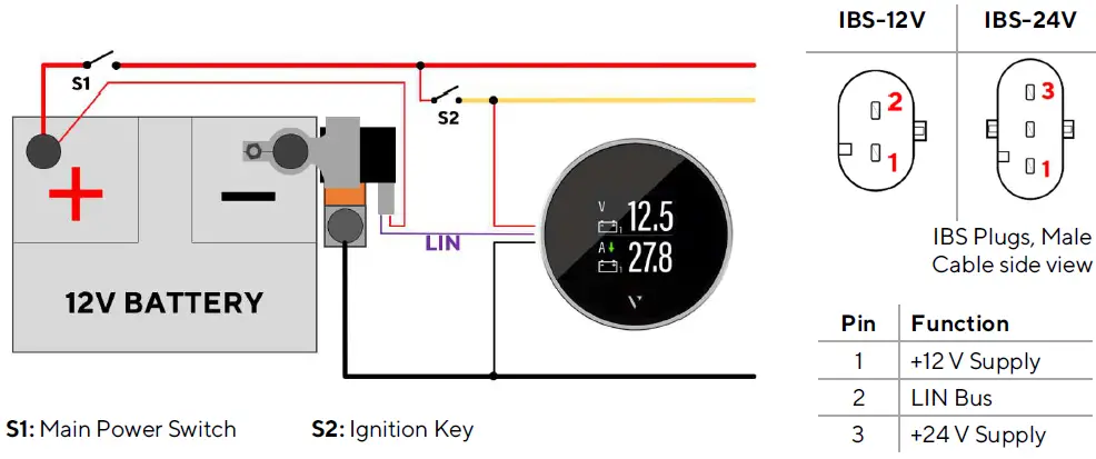
- The Intelligent Battery Sensor (IBS) is to be installed on the negative pole of the battery.
- The main ground connection of the vessel’s wiring must be attached to the pole adapter provided with the IBS.
- Currents on the wires that are connected to the pole of the battery directly, will not be measured by the sensor and will corrupt the calculated results like capacity, battery autonomy, and battery health.
- The 12V-/24V connection for the IBS must be connected to the positive pole of the battery. This connection may not be interrupted by the main switch.
CONFIGURATION
VMH FLEX CONFIGURATOR APP
- To configure the VMH Flex, some parameters must be configured, e.g. the display type, the connected sensor, and its calibration, or the alarm threshold.
- This is possible with the smartphone app “VMH Flex Configurator”, which can be downloaded free of charge from the stores for both Android and iOS devices.
- Thanks to the passive NFC receiver, the VMH Flex device can be configured as described below without the need for a power supply.

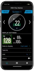
APP LAYOUT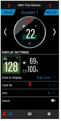
Segments:
- Read / Write buttons
- Press before connecting with the display
- Screen preview with screen number
- Shows how the current setting will look on the VMH Flex
- Parameter selection
- Define to see the correct data
- Tab selection
- screen tab | input tab | settings tab
THE CONFIGURATION PROCESS
Before defining any settings, the current configuration must be read from the VMH Flex by pressing the red button and holding the smartphone’s NFC interface directly on the screen of the gauge.
- READ
- CONFIGURE
- WRITE
The configurations are distributed over the three tabs accessible through the tab selection at the bottom of the screen.
 Define which data should be visible with the options in the Screen Tab. (More information in section “Setting up the Data Pages”)
 Enable the required analog inputs and disable the others in the Input Tab. (More information in the sections “Configure an Analog Sensor” and “Configure the IBS Input”)
 Choose the basic screen settings in the Settings Tab. (More information in section “Screen Settings”)
- Once all configurations have been defined, press the write button and hold the smartphone again on the screen.
SETTING UP THE DATA PAGES
- In the Data Tab use the arrow buttons to scroll through the previews of the different screens. For each of the five screens, the following configurations shall be defined.
- Layout: Choose between the single or dual layout by pressing the according preview in the section “Display Settings”.
- Gauge Type: Select the desired value, that should be visible through the dropdown menu “Data to display”.
- Depending on the selected gauge type, it is possible to define some more parameters. Not all of them are available for every type.
- Number: Select the appropriate instance. The instance describes which of the engines, tanks, or sensors is meant if there is more than one in the system (e.g.: Tank1/Tank2/…).
- (Note that the numerating starts at 1. Some manufacturers will call the first device “instance 0”)
- Unit: Selection between metric, imperial, or nautical measurement units.
- Bargraph: Define the range of values displayable on the bar graph.
- Alarm: For some gauge types, the VMH Flex can trigger an alarm if a certain threshold is reached. If the alarm option is enabled through the switch, the level of this threshold can be defined here.
- If the dual layout is selected, all these settings are doubled for the second data as well.
CONFIGURE AN ANALOG INPUT
- The settings for the analog data inputs can be found in the input tab. The switches enable or disable the different data inputs. When an input is enabled, the according menus will be expanded.
- Sensor: Defines which type of sensor is connected to the input.
- Number: Selection of the sensor’s instance. The instance describes which of the engines, tanks, or sensors is meant if there is more than one available in the system (e.g.: Tank1/Tank2 …).
- Characteristics: The sensor’s characteristics must be entered into the table. For Veratron sensors the curves are predefined and can be imported to the table by selecting the according option from the dropdown menu “Characteristics”.
- Pulses: When using the frequency input, the specification of the number of pulses per engine revolution (for rpm) or the number of pulses per km or mile (for boat speed) depending on the connected signal source must be entered.
- The VMH Flex – NMEA 2000 includes a gateway function. Therefore, the values measured on the analog inputs will be shared on the NMEA 2000 network.
- The gateway function can also be used on sensors without their values being shown on the VMH Flex display.
- The VMH Flex J1939 does not send out the data from the analog inputs. The data is only displayed on the screen.
CONFIGURE THE IBS INPUT
- When an Intelligent Battery Sensor (IBS) is connected to the LIN-Bus (Pin 5 – Blue/White), the Input “IBS Sensor” must be enabled in the “Inputs” tab. For the sensor to work, these parameters must be defined.
- Sensor: Selection of the exact type of Intelligent Battery Sensor.
- Battery Type: Selection of the fitting battery type. (Gel, AGM or Flooded)
- Capacity: Type in the capacity of the battery. The number can be found written on the battery. On a battery pack, add up these numbers of the different batteries.
SCREEN SETTINGS
- To change the illumination levels, the clock offset, and the time format, use the configurations in the settings tab.
- Illumination: Use the sliders to define the brightness levels for the day and night mode.
- The day or night mode depends on the applied signal on the illumination input (Pin 6 – Red/White).
- Clock Offset: The time is not counted internally. It can only be received via CAN (NMEA 2000 or J1939). On NMEA 2000 only the UTC+00:00 time is sent.
- This means, the device must be configured to match the time in your current time zone. To do so select the according offset in this menu.
- Clock Format: Select whether the time should be displayed in a 12h or 24h format.
SUPPORTED CONFIGURATIONS
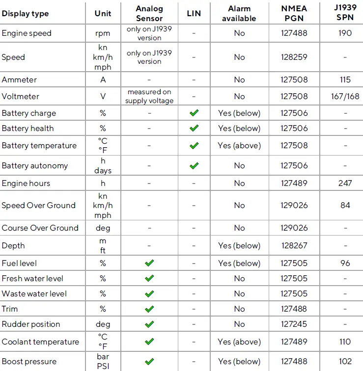
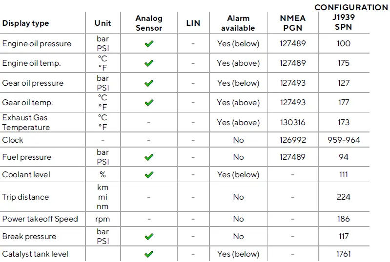
Supported configurations can be updated at any time. Make sure you always use the latest version of the app.
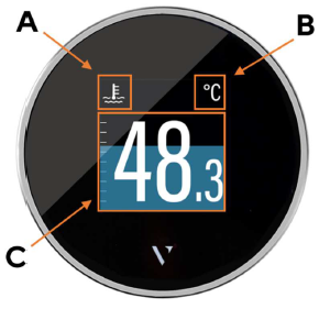
DISPLAY LAYOUT
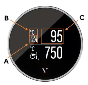
SINGLE LAYOUT
- A. Symbol
- Indicates, which data type is displayed right now.
- For the data types, that support this function, there is also the instance indicated here.
- B. Unit
- Shows the unit of the currently displayed data.
- For some data types, it’s possible to change the unit in the settings. (See table “Supported Configurations”)
- C. Measured value
- This shows the numeric value of the dedicated measured data. If there aren’t any values received for this data type or they are out of range, the display will show “—“.
Coloured Graph
- The colored graphic in the background is a bar diagram that puts the measured value in perspective.
- This function isn’t supported for all data types.
- The white lines on the left side show the escalation.
DUAL LAYOUT
- A. Symbol
- Indicates, which data type is displayed right now.
- For the data types, that support this function, there is also the instance indicated here.
- B. Unit
- Shows the unit of the currently displayed data.
- For some data types, it’s possible to change the unit in the settings. (See table “Supported Configurations”)
- C. Measured Value
- This shows the numeric value of the dedicated measured data. If there isn’t any data received for this data type or the values are out of range, the display will show “—“.
- The bar graph can’t be displayed in the dual layout for any value.
ALARM DISPLAY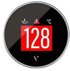
Single data layout
- When an alarm occurs the bar graph turns red, and a red alarm symbol is displayed in the top part of the display between the data symbol and the unit.
- The display returns to normal operation mode once the alarm is not detected anymore.
DISPLAY LAYOUT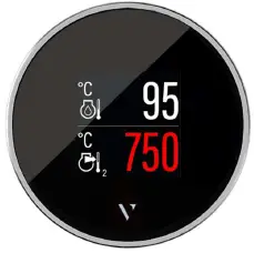
Dual data layout
- When an alarm occurs on any of the two displayed data, the numeric digits of the affected data become red.
- In the example above, the data at the bottom of the screen (Exhaust Gas Temperature) has an alarm active.
- The display returns to normal operation mode once the alarm is not detected anymore.
TECHNICAL DATA
DATASHEET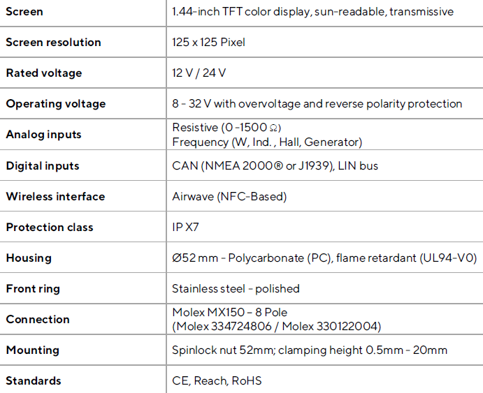
SUPPORTED NMEA 2000® PGNS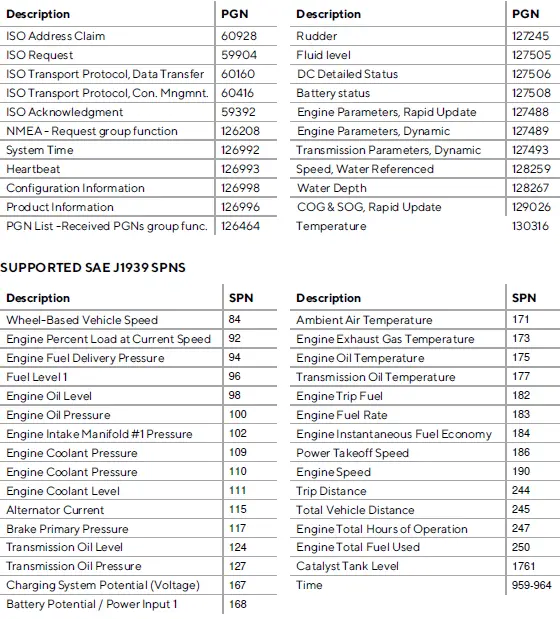
ACCESSORIES
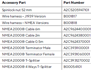
Visit http://www.veratron.com for the complete list of available accessories.
REVISION HISTORY
Version Changes Date
Rev. AA − Initial Release 12.12.2024
- veratron AG
- Industriestrasse 18
- 9464 Rüthi, Switzerland
- T +41717679111
- info@veratron.com
- veratron.com
- Partial or complete distribution, translation, or reproduction of this document is strictly prohibited without the prior written consent of veratron AG, except for the following measures:
- Print all or part of the document in its original size.
- Reproduction of the content without modification and explanation by Veratron AG as a copyright holder.
- Veratron AG reserves the right to make changes or improvements to the related documentation without prior notice.
- Requests for approval, additional copies of this manual, or technical information concerning it should be addressed to veratron AG.
Documents / Resources
 |
veratron VMH FLEX 1.4 Inch Colour Multi Function Display [pdf] User Manual B00127801, B001226, VMH FLEX 1.4 Inch Colour Multi Function Display, VMH FLEX, 1.4 Inch Colour Multi Function Display, Multi Function Display, Function Display |