Schneider Electric TM173O Programmable Logic Controller Module

Specifications
- Reference: TM173O
- Display: Digital Outputs
- Digital Inputs: 6
- Analog Outputs: 5
- Analog Inputs: 6
- Communication Ports: CAN Expansion bus, USB (type C), RS-485 serial ports
- Supply: 24Vac/Vdc
Product Usage Instructions
Safety Instructions
Ensure all connections are secure before applying power to the unit. Use only the specified voltage for operation to avoid risks of electric shock, explosion, or arc flash.
Installation
Install the equipment following the guidelines provided in the appropriate hardware guide. Verify proper grounding and power connections before powering up.
Operation
Operate the equipment as per the specified voltage requirements. Ensure all devices are powered off before making any changes or maintenance.
Maintenance
Perform maintenance tasks only when the equipment is powered off and disconnected from any power source. Follow the manufacturer’s recommendations for servicing.
FAQ
- Q: What should I do if I encounter a regulatory incompatibility?
- A: Ensure compliance with all national laws and regulations to prevent any risks of injury, equipment damage, or legal consequences.
- Q: Who should install and service the electrical equipment?
- A: Electrical equipment should only be installed, operated, serviced, and maintained by qualified personnel to ensure safety and proper functioning.
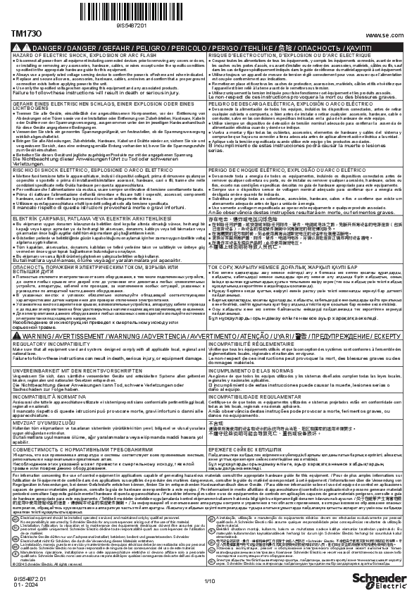
DANGER
HAZARD OF ELECTRIC SHOCK, EXPLOSION OR ARC FLASH
- Disconnect all power from all equipment including connected devices prior to removing any covers or doors, or installing or removing any accessories, hardware, cables, or wires except under the specific conditions specified in the appropriate hardware guide for this equipment.
- Always use a properly rated voltage sensing device to confirm the power is off where and when indicated.
- Replace and secure all covers, accessories, hardware, cables, and wires and confirm that a proper ground connection exists before applying power to the unit.
- Use only the specified voltage when operating this equipment and any associated products.
- Failure to follow these instructions will result in death or serious injury.
| Reference | Description | Display | Digital Outputs | Digital Inputs | Analog Outputs | Analog Inputs | Communication Ports | Power Supply |
| TM173OBM22R | M173 Optimized Blind 22 I/Os | No | 5 | 6 | 4 | 7 | CAN Expansion bus
USB (type C) RS-485 serial ports |
24Vac/ Vdc |
| TM173ODM22R | M173 Optimized Display 22 I/Os | Yes | 5 | 6 | 4 | 7 | ||
| TM173ODM22S | M173 Optimized Display 22 I/Os, 2 SSR | Yes | 3 + 2 SSR | 6 | 4 | 7 | ||
| TM173ODEM22R(1) | M173 Optimized Display 22 I/Os, EEVD | Yes | 5 | 6 | 4 | 7 | ||
| TM173OFM22R (1) | M173 Optimized Flush mounting 22 I/Os | Yes | 5 | 6 | 4 | 7 | USB (type C)
RS-485 serial ports |
|
| TM173OFM22S(1) | M173 Optimized Flush mounting 22 I/Os, 2 SSR | Yes | 3 + 2 SSR | 6 | 4 | 7 | ||
| TM173DLED(1) | M173 Optimized Remote Display LED | Yes | – | – | – | – | – | – * |
Powered by the controller.
Available soon.
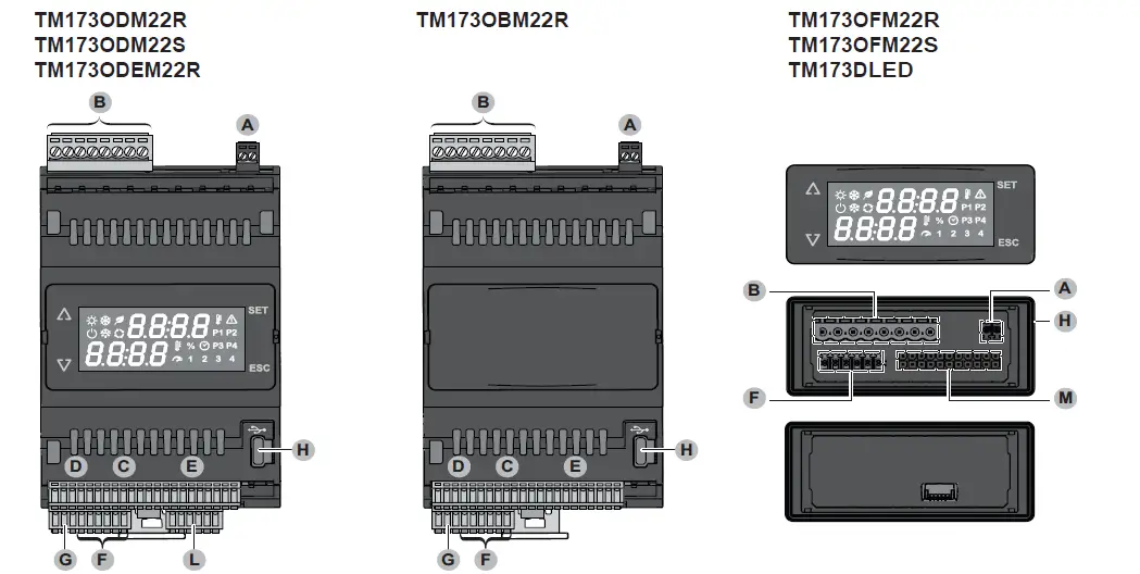
TM173ODM22R / TM173ODM22S / TM173ODEM22R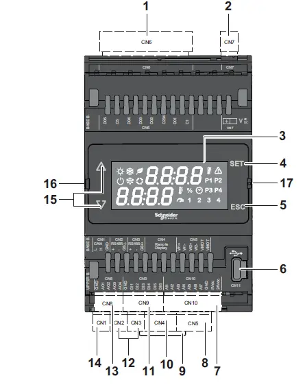
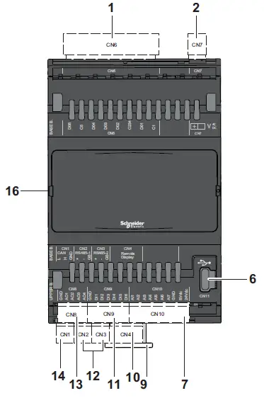
TM173OBM22R
TM173OFM22R / TM173OFM22S / TM173DLED
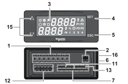
TM173OFM22R / TM173OFM2SS
Rear view
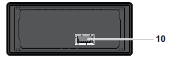
TM173DLED
Rear view
- Digital outputs
- Power supply
- Display
- Enter key
- Escape key
- USB (Type C)
- Analog inputs
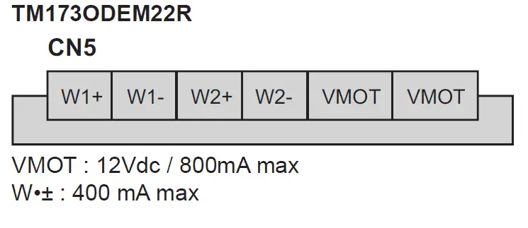
- Valve driver output (only for TM173ODEM22R model)
- Clip-on lock for 35-mm (1.38 in.) top hat section rail (DIN rail)
- Connector for remote display
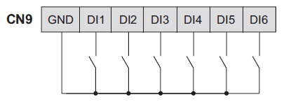
- Digital inputs
- Serial port RS-485
- Analog outputs
- CAN Expansion bus
- Navigation keys
- Connector to communication module
- Battery backup socket connector (only for TM173ODEM22R model)
WARNING
UNINTENDED EQUIPMENT OPERATION
- Use appropriate safety interlocks where personnel and/or equipment hazards exist.
- Install and operate this equipment in an enclosure appropriately rated for its intended environment and secured by a keyed or tooled locking mechanism.
- Power line and output circuits must be wired and fused in compliance with local and national regulatory requirements for the rated current and voltage of the particular equipment.
- Do not disassemble, repair, or modify this equipment.
- Do not connect any wiring to reserved, unused connections, or to connections designated as No Connection (N.C.).
Failure to follow these instructions can result in death, serious injury, or equipment damage
WARNING: This product can expose you to chemicals including lead and lead compounds which are known to the State of California to cause cancer and birth defects or other reproductive harm.
For more information go to: www.P65Warnings.ca.gov .
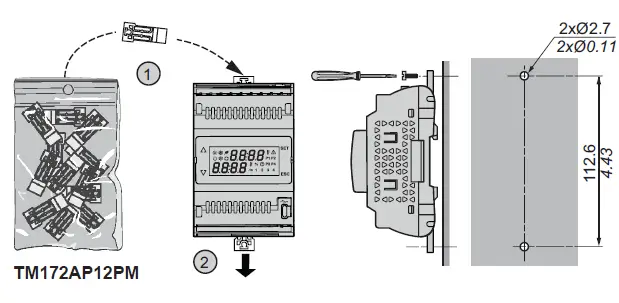
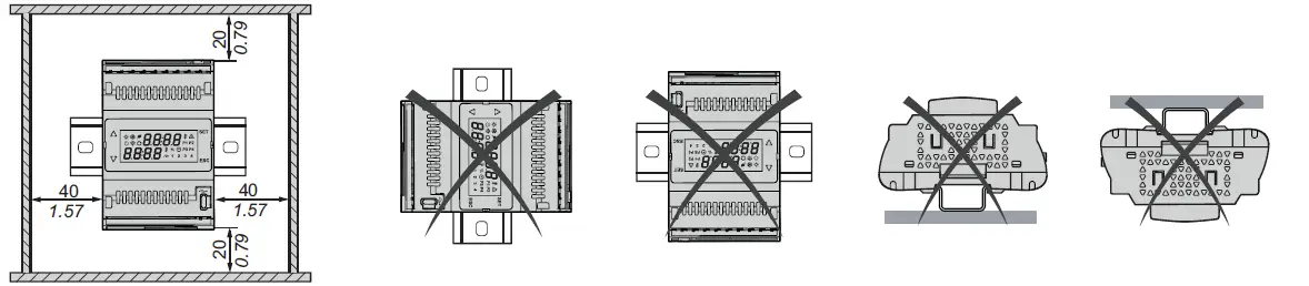
Mounting
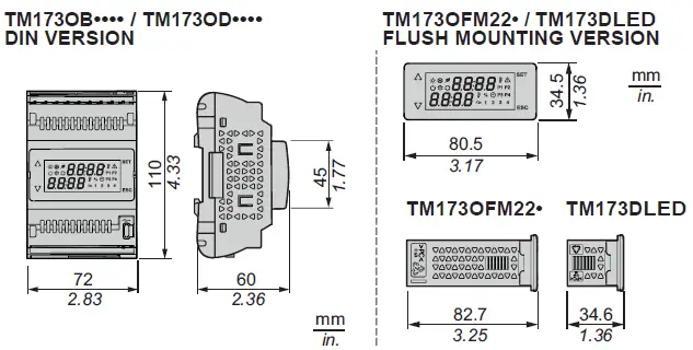
TM173OB•••• / TM173OD•••• DIN VERSION
Top hat section rail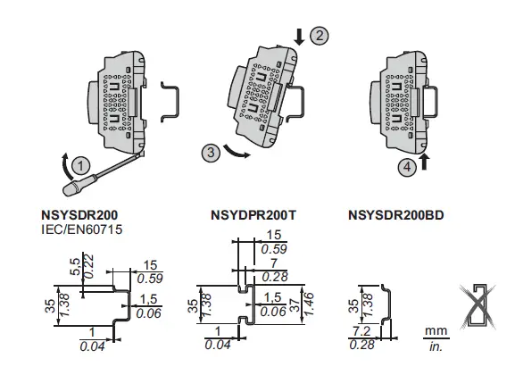
TM173OFM22• / TM173DLED FLUSH MOUNTING VERSION
Mounting on panel with the special brackets provided
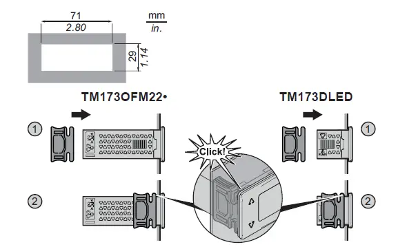
Panel
Dimensions
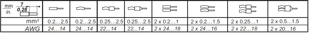
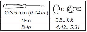
CN7
Pitch 3.50 mm (0.14 in.) or 3.81 mm (0.15 in.)
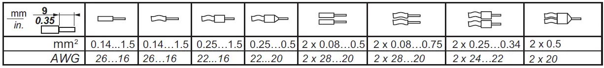
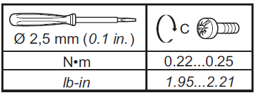
Use copper conductors only.
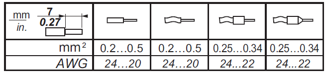
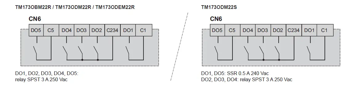
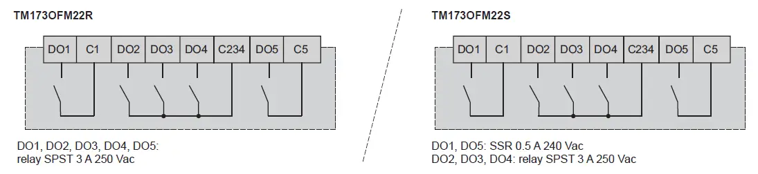
CN6
Pitch 5.08 mm (0.20 in.) or 5.00 mm (0.197 in.)
Use copper conductors only.
- CN9 D
- CNIO
- CN2,
- CNI
- CN5
Use copper conductors only.
Power supply
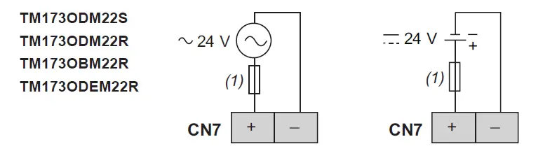
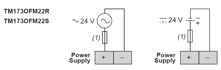
Type T fuse 1.25 A
WARNING
POTENTIAL OF OVERHEATING AND FIRE
- Do not connect the equipment directly to line voltage.
- Use only isolating SELV, Class 2 power suppliers/transformers to supply power to the equipment.
- Failure to follow these instructions can result in death, serious injury, or equipment damage.
Wiring diagram
Digital Outputs
Digital inputs
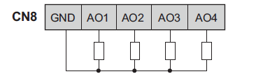
Analog Outputs
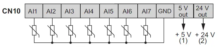
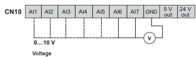
Analog inputs
- Max current: 50 mA.
- Max current: 125 mA.
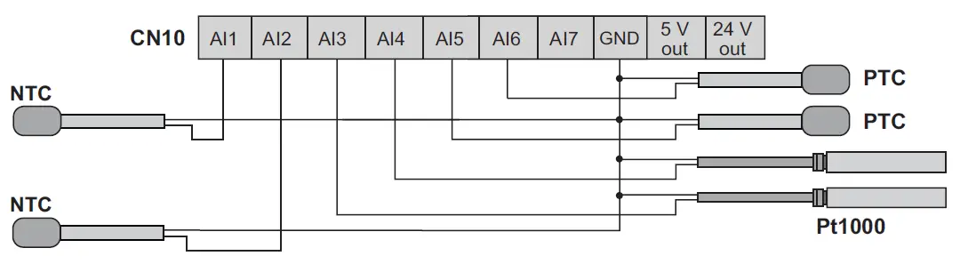
Example
NTC – PTC – Pt1000 probe connection
Example
Transducer connection
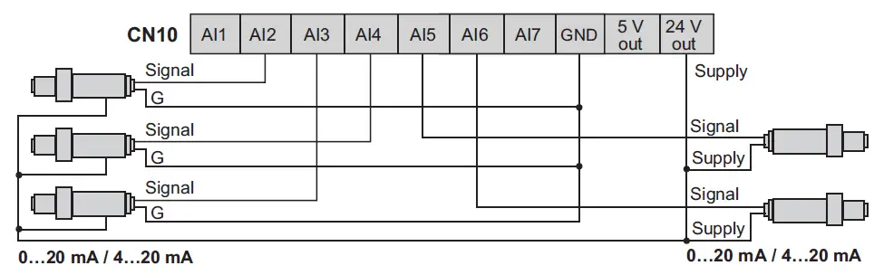
- Signal
- Voltage 0…5 V ratiometric
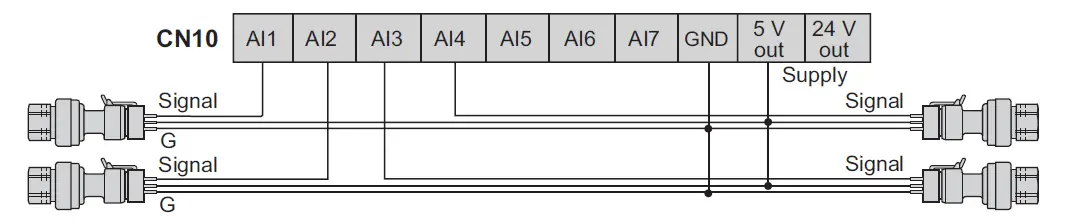
Microfit connector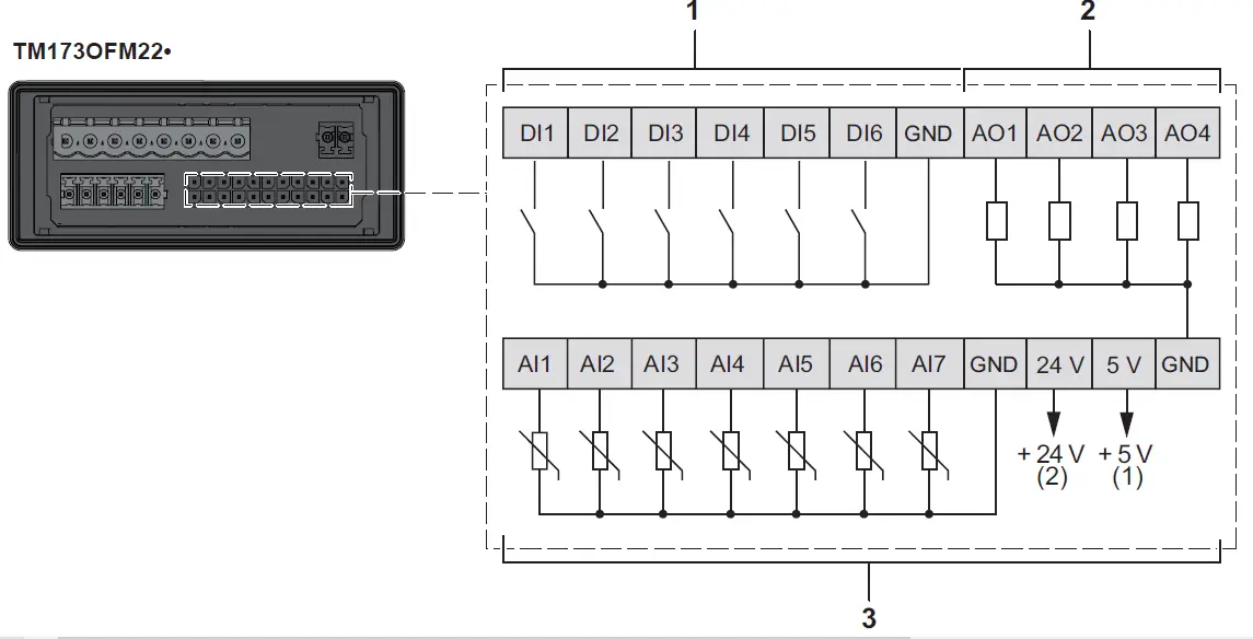
- Max current: 50 mA.
- Max current: 125 mA
- Digital inputs
- Analog outputs
- Analog inputs
RS-485-1 – Modbus SL
RS-485-2 – Modbus SL
Serial line port
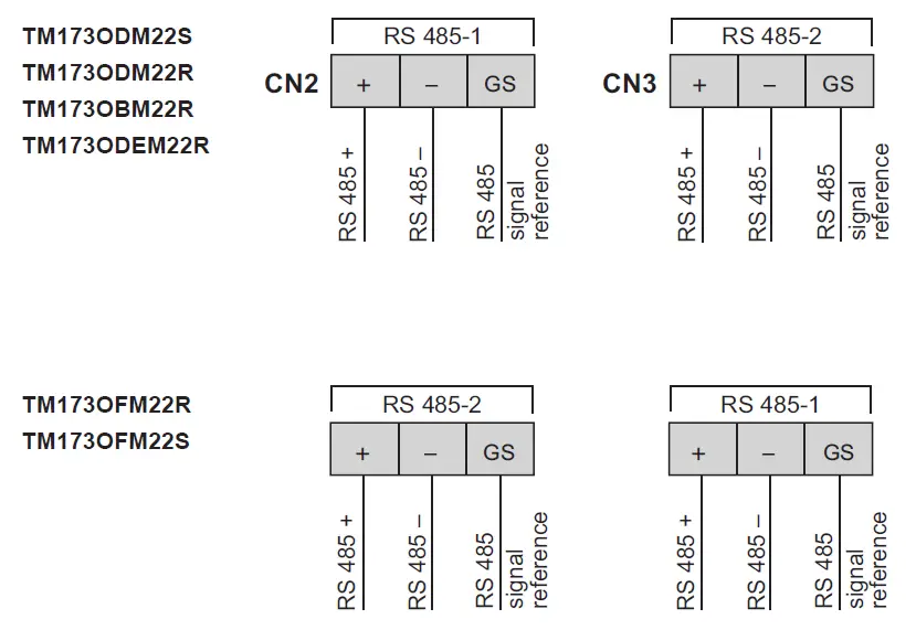
Apply 120 Ω terminal resistor. (if end device of the bus).
CAN Expansion bus
Apply 120 Ω terminal resistor (if end device of CAN expansion bus).
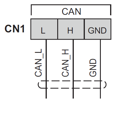
CAN connection example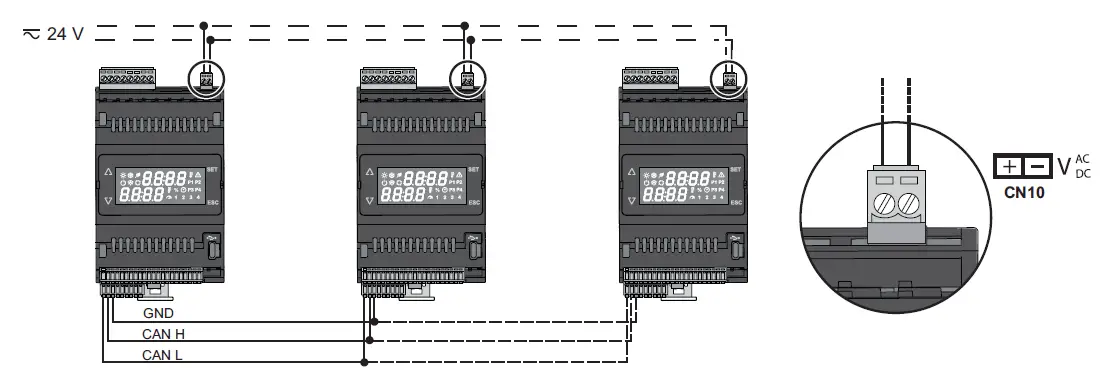
USB connections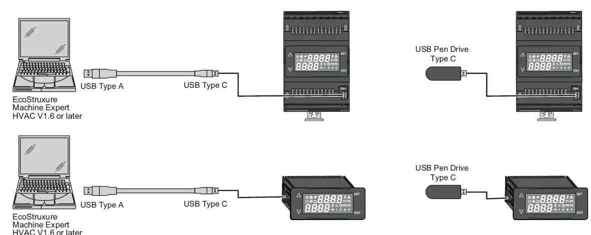
Valve Outputs
Build-in protection against overload (only TM173ODEM22R) and short-circuit
First switch on
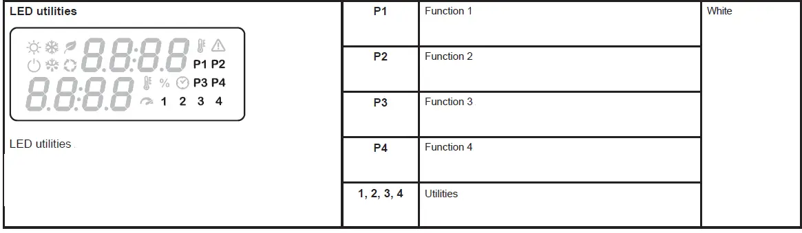
LED states and Operating Modes
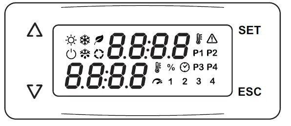
LED states and Operating Modes 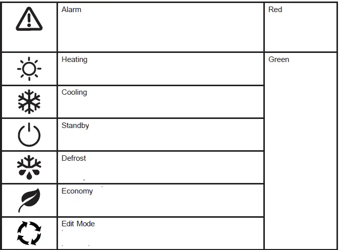

Technical Data
The product complies with the following harmonized Standards
- Construction of control : Electronic automatic Incorporated Control
- Purpose of control : Operating control (non-safety related)
- Environmental front panel rating Open Type
- Degree of protection provided by enclosure IP20
- Method of mounting See page 4
- Type of action 1.B / 1.Y
- Pollution degree 2 (Normal)
- Overvoltage category II
- TM173OB•••• / TM173OD•••• : Power supply 24 Vac (±10%) 50 / 60 Hz 20…38 Vdc
- TM173OFM22• : Power supply not isolated (RS-485 ISO)
- Ambient operating conditions
- TM173OB••••
- TM173OD••••
- TM173OFM22• : -20…65 °C (-4 …149 °F) 5…95 % (1)
- TM173ODEM22R : -20…55 °C (-4 …131 °F) 5…95 % (1)
- Transportation and storage conditions -30…70 °C (-22…158 °F) 5…95 % (1)
- Software class A
 DISPOSAL: The equipment (or product) must be subjected to separate waste collection in compliance with the local legislation on waste disposal.
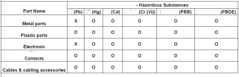
This table is made according to SJ/T 11364.
- O: Indicates that the concentration of hazardous substance in all of the homogeneous materials for this part is below the limit as stipulated in GB/T 26572.
- X: Indicates that concentration of hazardous substance in at least one of the homogeneous materials used for this part is above the limit as stipulated in GB/T 26572.
INFORMATION
- Eliwell Controls s.r.l.
- Via dell’Industria, 15 • Zona Industriale Paludi •
- 32016 Alpago (BL) ITALY
- T +39 0437 986 111
- T +39 0437 986 100 (Italy)
- T +39 0437 986 200 (other countries)
- E saleseliwell@se.com
- Technical helpline +39 0437 986 300
- E techsuppeliwell@se.com
- www.eliwell.com
 UK Authorized Representative
- Schneider Electric Limited
- Stafford Park 5
- Telford, TF3 3BL
- United Kingdom
Documents / Resources
 |
Schneider Electric TM173O Programmable Logic Controller Module [pdf] Instruction Manual TM173OBM22R, TM173O, TM173O Programmable Logic Controller Module, TM173O, Programmable Logic Controller Module, Logic Controller Module, Controller Module |


