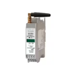
![]() Série S311D-XX-L / S311D-XX-H
Série S311D-XX-L / S311D-XX-H
INSTALLATION MANUAL
PRELIMINARY WARNINGS
The word WARNING preceded by the symbol![]() indicates conditions or actions that put the user’s safety at risk.
indicates conditions or actions that put the user’s safety at risk.
The word ATTENTION preceded by the symbol![]() indicates conditions or actions that might damage the instrument or the connected equipment. The warranty shall become null and void in the event of improper use or tampering with the module or devices supplied by the manufacturer as necessary for its correct operation, and if the instructions contained in this manual are not followed.
indicates conditions or actions that might damage the instrument or the connected equipment. The warranty shall become null and void in the event of improper use or tampering with the module or devices supplied by the manufacturer as necessary for its correct operation, and if the instructions contained in this manual are not followed.
 |
WARNING: The full content of this manual must be read before any operation. The module must only be used by qualified electricians. Specific documentation is available via QR-CODE shown on page 1. |
| The module must be repaired and damaged parts replaced by the Manufacturer. The product is sensitive to electrostatic discharges. Take appropriate measures during any operation. |
|
 |
Electrical and electronic waste disposal (applicable in the European Union and other countries with recycling). The symbol on the product or its packaging shows the product must be surrendered to a collection centre authorized to recycle electrical and electronic waste. |
This document is the property of SENECA srl. Copies and reproduction are prohibited unless authorised.
The content of this document corresponds to the described products and technologies.
Stated data may be modified or supplemented for technical and/or sales purposes.
MODULE LAYOUT

Weight: 170 g; Enclosure: Self-extinguishing PC/ABS material, black.
BUTTON POSITION
4-6-8-11-DIGIT DISPLAY

OPERATION DESCRIPTION
The measurement of the digital input frequency or the totalizer value is translated into an analogue or digital output signal.
The frequency value or alternatively the totalizer value can also be viewed via the display; in the 11-digit model (4 + 7) both values can be displayed simultaneously (4 digits: frequency value, 7 digits: totalizer value). The values are also available via MODBUS-RTU protocol from the RS485 port (via optional board).
Setting mode:
All the parameters of the instrument can be set via the Programming Menu or RS485 (via optional board). The alarm thresholds can also be set quickly via the specific Quick Alarm Menu. The dedicated Easy Setup software for programming/ configuring the module was also developed (see www.seneca.it).
Retransmission mode:
The instrument accepts the following retransmission modes:
Analogue output: The measurement of the frequency of the digital input is translated into an analogue output signal (current or voltage).
Digital output: The output generates an impulse every time the totalization is increased or decreased. A pulse of duration ≥ ~ 100 ms is generated. The output follows the totalizer up to the maximum value of approximately 4.7 Hz. As the counting frequency increases (up to the maximum value shown above), pulses are gradually lost until an output is obtained always at a low logic level. The output is normally high.
TECHNICAL SPECIFICATIONS
| STANDARDS | EN61000-6-4 Electromagnetic emissions, industrial environment. EN61000-6-2 Electromagnetic immunity, industrial environment. EN61010-1 Safety Install a fuse with a maximum capacity of 1 A near the module. |
| ENVIRONMENTAL CONDITIONS | Temperature: -10 ÷ + 65°C Humidity: 30% ÷ 90% non condensing. Storage temperature: -20 + 85° Protection rating: IP65 (on the front with appropriate gasket) |
| INSULATION | 2500 Vdc between each pair of ports (including those belonging to the optional board) |
| POWER SUPPLY | S311D-XX-L: 10 ÷40 Vdc, 19 ÷ 28 Vac, 50 ÷ 60 Hz, max. 3 W S311 D-XX-H: 85 ÷ 265 Vac, 50 ÷ 60 Hz, max. 3 W |
| CONNECTIONS | Removable screw terminals, 3.5 mm/5.08 mm pitch |
| DIGITAL INPUT | Type: Reed, Npn (2 wires), npn 24 V (3 wires) or pnp 24 V (3 wires), NAMUR, Photoelectric (Astra), Hall, 24 V input, TTL, Variable reluctance. Absorbed current: max. 7 mA Vmax.: 28 Vdc |
| ANALOGUE OUTPUT | Applied current: 0 ÷ 20 mA, max. load resistance 500 W Voltage: 0 ÷ 10 V, min. load resistance 1 kW Configurable start and end of scale Resolution: 2 mA / 1 mV Response time: 5 ms Maximum measurement field errors: Calibration error: 0.1% Thermal coefficient: 0.01%/°K Linearity error: 0.05% EMI (electromagnetic interference): < 1% |
| DIGITAL OUTPUT | Open Collector type, Imax: 50 mA, Vmax: 30 V |
| RELAY OUTPUT | Capacity: 8 Al 250 Vac (available only on optional board) |
| AUX. DIGITAL INPUT | Optoinsulated, Vmin: 10 V, Vmax: 30 V (available only on optional board) |
Alarms on frequency or totalizer measurement (optional board):
Two alarms can be activated on the measurement of the frequency of the digital input signal or on the totalizer threshold values, each of which, if enabled, can be configured as follows:
- Alarm on the minimum threshold.
- Alarm on the maximum threshold.
- Alarm on the minimum held threshold (does not automatically reset).
- Alarm on the maximum held threshold (does not automatically reset).
- Alarm on the totalizer threshold value (does not reset automatically).
For each alarm it is possible to set threshold and hysteresis. For the totalizer alarm, the hysteresis is not considered. If the alarm is maximum the reset value is Threshold-Hysteresis, if it is minimum the reset value is Threshold + Hysteresis. The status of the alarms can be viewed via the two LEDs on the front panel and from the relays (if the optional board is used). The relays switch status when the alarm occurs and return to the initial state when it is reset (if held). The alarms held are reset in normal operation by pressing the UP + OK/MENU keys for a few seconds. For the totalizer alarm, the alarms are reset by pressing the UP+DOWN+ OK/MENU keys, via MODBUS or from the auxiliary digital input.
Totalizer
As an alternative to measuring the frequency of the digital input signal, it is possible to view the value of the associated totalizer (saved in non-volatile memory). Both values are available simultaneously in the 11-digit indicators (4+7).
The totalizer can be:
Increasing: it is increased by one unit at each rising edge of the digital input.
- Decreasing: it is decreased by one unit at each rising edge of the digital input.
Once the maximum or minimum limit is reached, counting restarts from zero.
It is also possible to set a reduction ratio by which to divide the totalizer value; the resulting value will then be displayed.
Reset can also take place in the following three ways:
- From auxiliary digital input (if enabled).
- By pressing the three keys simultaneously (if enabled).
- Via Modbus register.
Display of frequency measurement value or totalized value
Three types of operation can be set (except for the 11-digit models that display both the frequency value and the totalizer
value together) that define the display modes:
- Type 0: both frequency value and totalizer value display. Pressing UP for a few seconds you access the frequency display, pressing DOWN for a few seconds displays the totalized value. When passing to the frequency value for a few seconds the writing
 appears, passing to the totalized value the writing
 appears for a few seconds.
 - Type 1: frequency measurement display only.
- Type 2: totalizer display only
Average and frequency measurement filtering
The frequency value can be averaged over a settable number of samples. The average value is then filtered through the 20-level exponential filter and then shown on the display.
VLF Mode
If the full scale in Hz for measuring the frequency (HI-F) ≤ 1 Hz the instrument goes to Very Low Frequency Mode (VLF) thanks to which the minimum detectable frequency value is equal to 0.00015 Hz (1 pulse every 111 minutes).
Password to access the menu
It is possible to enable password protection from the Programming Menu. The Quick Alarm Menu is always free of passwords.
ELECTRICAL CONNECTIONS
POWER SUPPLY

DIGITAL INPUT
 The internal power supply for the sensors, equal to 17 Vdc, is available at terminals 7 (+) and 10 (-).
ANALOGUE OUTPUT
 |
||
| Active output: already powered to be connected to passive inputs |
Passive output: not powered to be connected to active inputs. |
|
DIGITAL OUTPUT
 I max: V / R = 50 mA
OPTIONAL BOARD CONNECTIONS

Example:
Totalizer reset with power supplied entirely by the module

| FREQUENCY MEASUREMENT LIMITS: | TOTALIZER LIMITS | |||
| DISPLAY DIGITS | MIN. LIMIT | MAX. LIMIT | MIN. LIMIT | MAX. LIMIT |
| 4 | -1999 | 9999 | 0 | 9999 |
| 6 | -199999 | 999999 | 0 | 999999 |
| 8 | -2E+07 | 99999999 | 0 | 99999999 |
| 11 (4+7) | -1999 | 9999999 | 0 | 9999999 |
| PARAMETERS TO SET FROM THE MENU: |
|||
| Parameter code | Parameter name | SETTING RANGE AND DESCRIPTION | DEFAULT VALUE |
| Type of instrument operation | 0 = frequency and totalizer display function. 1 = only frequency measurement display function. 2 = only totalizer display function. |
0 = Instant. and Totaliz. | |
| Enables panel totalizer reset and auxiliary digital input | 0 = totalizer reset from panel and auxiliary digital input enabled. 1 = totalizer reset from panel and auxiliary digital input disabled. |
0 = Enables | |
| Password enabling for menu access | By setting a value other than 5477, the password will be requested when starting the menu (always 5477). | 5477 = Password disabled | |
| PARAMETERS TO SET FROM THE MENU: .n.P.t. | |||
| Input type | 1= Reed 2= npn 2 wires 3= npn 24 V (3 wires) 4= pnp 24 V (3 wires) 5= NAMUR 6= Photoelectric (ASTRA) 7= HALL 8= 24 V input 9= TTL input 10= Variable reluctance |
3 = npn 24 V (3 wires) | |
| Full scale (Hz) | Full scale in Hz to measure frequency. It also defines the frequency value associated with the Settable values The decimal point is imposed by Minimum value: 0, Max value depending on the display: 4 / 11 (4+7) digits: 9999 (without decimal point). 6 / 8 digits: 10000 (without decimal point). |
1000 Hz | |
| Position of decimal point in |
0 = no decimal point (e.g. 00009999), 1 = first digit (e.g. 0000999.9) 2 = second decimal point (e.g. 000099.99) 3 = third decimal point (e.g. 00009.999), 4 = fourth decimal digit (e.g. 0000.9999, only for 6 and 8 digit models). |
0 = Decimal point absent | |
| PARAMETERS TO SET FROM THE MENU: |
|||
| Start of the scales displaying frequency measurement | Frequency value displayed if the measured frequency is 0. Values within the limits see: TABLE1. | 0 | |
| Full scales displaying frequency measurement | Displayed frequency value if the measured frequency is Value within the limits see: TABLE1. |
1000 | |
| Frequency display decimal point position | 0 = no decimal point (ex. 12345678), 1 = first digit (e.g. 1234567.8) … … N digits display-1 For 11-digit models (4+7): max number of decimal places equal to 3 |
0 = Decimal point absent | |
| Filter level | 0= no filter 1 – 20 |
3 | |
| Number of samples on which to average the frequency value | Selectable values: 1 -10. | 1 | |
| PARAMETERS TO SET FROM THE MENU: |
|||
| Parameters related to alarm 1: accessible from menu Parameters related to alarm 2: accessible from menu |
|||
| Parameter code | Parameter name | SETTING RANGE AND DESCRIPTION | DEFAULT VALUE |
| Threshold for alarm 1. | If frequency meter then frequency value shown on the display (decimal point imposed by |
500 | |
| Threshold for alarm 1. | 100 | ||
| Hysteresis for alarm 1. | Hysteresis has no effect on the totalizer alarms. Settable values between the limits of TABLE 1 | 10 | |
| Hysteresis for alarm 2. | 10 | ||
| Alarm 1 type | 0 = Alarm not active 1 = Alarm on the minimum threshold 2 = Alarm on the maximum threshold 3 = Alarm on the minimum held threshold (does not automatically reset) 4 = Alarm on the maximum held threshold (does not automatically reset). 5 = Alarm on the totalizer threshold value. (does not automatically reset) |
0: Al 1 not active | |
| Alarm 2 type | 0: Al 2 not active | ||
| Relay 1: N.O. or N.C. | Relay operation: 0 = relay normally open (N.O.) 1 = relay normally closed (N.C.). |
0: N.O. | |
| Relay 2: N.O. or N.C. | 0: N.O. | ||
| PARAMETERS TO SET FROM THE MENU: |
|||
| Frequency display value associated with the minimum output value | Limits for scaling the retransmitted output see TABLE1. Decimal point imposed by |
0 | |
| Frequency display value associated with the maximum output value | 1000 | ||
| Type of retransmitted output | 1= 0 ÷ 10 V 2= 4 ÷ 20 mA 3= 0 ÷ 20 mA 4= Totalizer digital output |
2 = 4 ÷ 20 mA | |
| PARAMETERS TO SET FROM THE MENU: |
|||
| MODBUS Address | Settable values: from 1 to 255. | 1 | |
| Parity control type | 0= None 1= Even 2= Odd |
0 = None | |
| Delayed response time | Number of pauses of 6 characters each between the end of the Rx message and the beginning of the Tx. Settable values: 0 – 255. |
0 = No delay | |
| Serial communication speed | Serial communication speed in baud: 0= 1200 1= 2400 2= 4800 3= 9600 4= 14400 5= 19200 6= 38400 7= 57600 |
6 = 38400 | |
| PARAMETERS TO SET FROM THE MENU: |
|||
| Display contrast | Values from 1 (minimum contrast) to 20 (maximum) | 10 | |
| Totalizer type: Increasing or decreasing | 0 = The totalizer increases by one unit at each rising edge of the digital input. 1 = The totalizer decreases by one unit at each rising edge of the digital input. |
0 = UP | |
| Default settings | 1 = Overwrites the set parameters with the default values. | ||
| PARAMETERS TO SET FROM THE MENU: |
|||
| Parameter code | Parameter name | SETTING RANGE AND DESCRIPTION | DEFAULT VALUE |
 |
Totalizer ratio | Sets a value by which to divide the totalizer. Permitted values: 1- 9999. | 1 |
| Decimal point position in the totalizer display | 0 = no decimal point (e.g. 123456) 1 = first digit (e.g. 12345.6) 2 = second digit (e.g. 1234.56) …… N digits display – 1 For 11-digit models (4+7): max number of decimal places equal to 6. |
0: No decimal point | |
 |
|||
| Confirming with OK/MENU you save all parameters on a flash card and, after a few moments, reset the module. | |||
SUMMARY OF BUTTON ACTIONS (in display mode)
Below is a summary of the actions that can be performed from the button starting from the display phase (not programming). In order for the actions to be carried out, the pressure on the buttons must last a few seconds.
 |
Access to the programming menu. |  |
Access to the Quick Alarm Menu |
 |
If |
 |
If |
 |
Held alarm reset | Totalizer reset (if this function has been enabled by setting |
ERROR REPORTING
Any errors are also shown directly on the display.
Below are the possible warnings with their meaning.
![]() : Frequency measurement value to be displayed > Hi-d value by 2.5% or if the frequency measurement value to be displayed is > maximum that can be displayed.
: Frequency measurement value to be displayed > Hi-d value by 2.5% or if the frequency measurement value to be displayed is > maximum that can be displayed.
![]() : It can signal an error of the calibration memory at startup.
: It can signal an error of the calibration memory at startup.
The operation of the instrument is blocked while ModBus communication is available (if optional board).
ORDER CODES
| CODE | DESCRIPTION | |
| MODEL: | S311 | Indicator – totalizer with universal digital input. |
| DISPLAY | 4 | 4 digits |
| 6 | 6 digits | |
| 8 | 8 digits | |
| 11 | 4 + 7 digits | |
| POWER SUPPLY | H | 85 ÷ 265 Vac |
| L | 10 ÷ 40 Vdc, 19 ÷ 28 Vac | |
| OPTIONS | O | Optional board: RS485 Modbus port, 2 relay alarms and auxiliary digital input. Insulation: 1500 Vac between each port. |
| T | Calibration and configuration service | |
Programming menù diagram

ACCESS TO THE PROGRAMMING MENU
![]() Push the two buttons at the same time for 3 seconds
Push the two buttons at the same time for 3 seconds
QUICK ALARMS MENU SCHEME

CHANGE PARAMETERS
The change is made digit by digit. The digit to be modified flashes: in the figure it is surrounded by a frame. The diagram below refers to 4-digit indicators; for the other models it differs only by the number of digits displayed.

![]() : Increase the digit value by one unit
: Increase the digit value by one unit
![]() : Decreases the digit value of one unit
: Decreases the digit value of one unit
![]() Confirm the value of the digit and move on to the next one.
Confirm the value of the digit and move on to the next one.
If last digit: Confirms the value of the digit and press again on the parameter just set.
KNOWN VALUES SETTINGS
NEGATIVE VALUES: the last digit also allows you to enter the sign “-” or the value “-1”.
VALUES INSERTED OUTSIDE THE PARAMETER RANGE: returns the value within the range.
 http://www.seneca.it/products/s311d
DOCUMENTATION
![]()
![]() SENECA s.r.l.; Via Austria, 26 – 35127 – PADOVA
SENECA s.r.l.; Via Austria, 26 – 35127 – PADOVA
– ITALY; Tel. +39.049.8705359 – Fax +39.049.8706287
CONTACT INFORMATION
Technical support support@seneca.it
Product information sales@seneca.it
M100150-10
Documents / Resources
 |
SENECA S311D-XX-L Digital Input Indicator Totalizer [pdf] Instruction Manual S311D-XX-L, S311D-XX-H, Digital Input Indicator Totalizer, Input Indicator Totalizer, Digital Input Indicator, Input Indicator, Digital Indicator, Indicator |