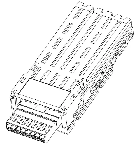
Schneider VW3A3424 HTL Encoder Interface Module
DANGER HAZARD OF ELECTRIC SHOCK, EXPLOSION, OR ARC FLASH
- Only appropriately trained persons who are familiar with and fully understand the contents of the present manual and all other pertinent product documentation and who have received all necessary training to recognize and avoid hazards involved are authorized to work on and with this equipment.
- Installation, adjustment, repair, and maintenance must be performed by qualified personnel.
- Verify compliance with all local and national electrical code requirements as well as all other applicable regulations with respect to grounding of all equipment.
- Before performing work and/or applying voltage on the equipment, follow the instructions given in the appropriate installation manual.
Failure to follow these instructions will result in death or serious injury.
Electrical equipment should be installed, operated, serviced, and maintained only by qualifed personnel. No responsibility is assumed by Schneider Electric for any consequences arising out of the use of this product.
© 2024 Schneider Electric. All Rights Reserved.
| Maximum Encoder Cable Length | ||||
| Encoder Supply | Minimum Cable Cross Section | Total Encoder Consumption | ||
| 100 mA | 175 mA | 200 mA | ||
|
12 Vdc |
0.2 mm² (AWG 24) | 100 m | 50 m | 50 m |
| 0.5 mm² (AWG 20) | 250 m | 150 m | 100 m | |
| 0.75 mm² (AWG 18) | 400 m | 250 m | 200 m | |
| 1 mm² (AWG17) | 500 m | 300 m | 250 m | |
| 1.5 mm² (AWG15) | 500 m | 500 m | 400 m | |
|
15 Vdc |
0.2 mm² (AWG 24) | 250 m | 150 m | – |
| 0.5 mm² (AWG 20) | 500 m | 400 m | – | |
| 0.75 mm² (AWG 18) | 500 m | 500 m | – | |
| 24 Vdc | 0.2 mm² (AWG 24) | 500 m | – | – |
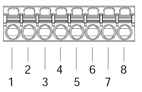
| PIN | SIGNAL | FUNCTION | ELECTRICAL CHARACTERISTICS |
| 1 | A+ | Channel A | Incremental Signal: +12Vdc or +15Vdc or +24Vdc
Input Impedance: 2kΩ Max Frequency: 300kHz Low level: ≤2Vdc High level: ≥9Vdc |
| 2 | A- | Channel /A | |
| 3 | B+ | Channel B | |
| 4 | B- | Channel /B | |
|
5 |
V+ |
Software configurable encoder supply voltage | +12Vdc / 200mA or
+15Vdc / 175mA or +24Vdc / 100mA |
|
6 |
V+ |
||
| 7 | 0V | Reference potential for encoder supply |
– |
| 8 | 0V | ||
| SHIELD | Overall cable shielding for signal lines | The shield has to be connected to the drive cabling plate | |
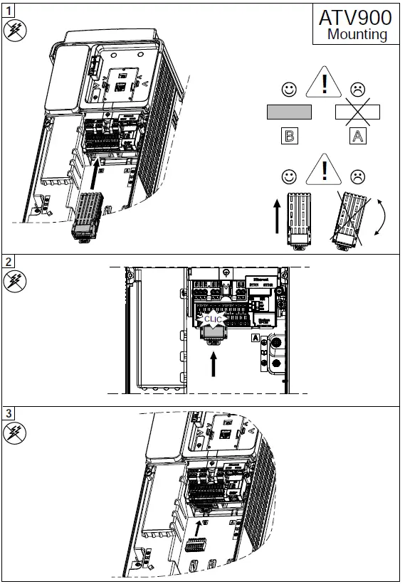
Encoder can be configured in [Complete settings] → [Encoder configuration].
For more information, refer to the ATV900 Programming Manual (NHA80757).
| PUSH PULL | OPEN COLLECTOR | |||||||||
|
PIN |
TWISTED WIRE PAIR |
A/AB/B DIFFERENTIAL |
AB SINGLE ENDED | A SINGLE-ENDED |
A/AB/B DIFFERENTIAL |
AB PNP |
AB NPN |
A PNP |
A NPN |
I/O |
| 1 |
1 |
R | R | R | R | R | R** | R | R** | I |
| 2 | R | R* | R* | R | R* | R | R* | R | I | |
| 3 |
2 |
R | R |
– |
R | R | R** | – | – | I |
| 4 | R | R* | – | R | R* | R | – | – | I | |
| 5 | 3 | R | R | R | R | R | R | R | R | O |
| 6 | Opt. | – | – | – | – | – | R** | – | R** | O |
| 7 | 3 | R | R | R | R | R | R | R | R | O |
| 8 | Opt. | – | R* | R* | – | R* | – | R* | – | O |
|
SHIELD |
R |
R |
R |
R |
R |
R |
R |
R |
– |
|
| R: Required *: The inputs have to be wired to the 0V pins
– : Not required **: The inputs have to be wired to the V+ pins Opt. : Optional |
||||||||||
R: Required *: The inputs have to be wired to the 0V pins
– : Not required **: The inputs have to be wired to the V+ pins
Opt. : Optional
MANUFACTURER
Schneider Electric Industries SAS
35 rue Joseph Monier
Rueil Malmaison 92500 France
UK REPRESENTATIVE
Schneider Electric Limited
Stafford Park 5
Telford, TF3 3BL United Kingdom
Documents / Resources
 |
Schneider VW3A3424 HTL Encoder Interface Module [pdf] User Guide VW3A3424 HTL Encoder Interface Module, VW3A3424, HTL Encoder Interface Module, Interface Module, Module |