Compulab Robo Designer User Guide
![]()
Compulab offers service and tools for efficient design and manufacturing of custom boards containing computer core and peripherals. This service and tools are collectively named RoboDesigner. It enables user to specify required functions, specify board size, connectors type and location, and then receive functional board which is matching to his specifications. It will include Linux installed and supporting all selected functions. RoboDesigner doesn’t require user to have hardware or software engineering skills. The finalized custom board can be efficiently manufactured in any quantity.
RoboDesigner Advantages
- Creates fully customized board with computer and peripherals
- Allows selection of size, connectors types and position
- Doesn’t require engineering skills
- Saves 95% of development time, effort and costs
- Efficient for any quantity, from single unit to mass production
How it works …
- You have to arrive with a list of required function and tentative mechanical specs.
- RoboDesigner tool provides simple intuitive interface to specify functions you need, board shape and connector locations. You can experiment with these as long as necessary. It is possible to design and save many different versions.
- You can review 2D and 3D mechanical specs from the tool itself or by generation DXF files.
- Next step is to request production. The tool will perform check to acknowledge that requested design is indeed production-able, and then will ask you to place an online order.
- As order placed, the design is forwarded to Compulab engineering. We will check and approve the design, communicate with you if necessary, and initiate automatic process of PCB manufacturing.
- After PCB manufacturing, it is assembled and tested with aid of robotic tools. Computer core is programmed with operating system.
- Prototype boards are then shipped to you.
- It is possible to order any additional quantity of the same design. If production volume increases, we will prepare setup for our fast assembling lines and so unit price will be optimized accordingly.
User Guide
If you are first time user, you need to register. Click on login icon in the top right corner and follow instructions.
![]()
To start using RoboDesigner click on [Select Functions] button on the menu bar. Tabs will be opened looking like this:
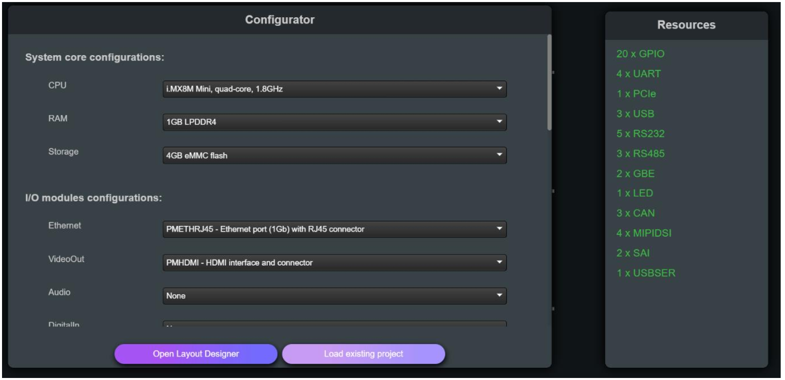
Left pane shows list of available computer, peripheral modules and auxiliary items. Select required functions from the list. When you select function, its name is displayed along with function description and type of connector used.
Right pane shows a list of resources available in the computer you selected. As you add more functions to your design, they are consuming these resources. For example, right pane initially shows availability of 3 USB ports. So you can put up to 3 USB ports in you design. Resource list is updated each time you are adding functions to your board. Resource availability limits amount and type of peripheral interfaces which can be placed in your design.
In general, it is not necessary for you to understand resource meaning, as they are managed automatically by RoboDesigner.
Once you selected required functions, click on Layout Designer. Note that at any stage you can return to Functions Selection in order to add or remove functions.
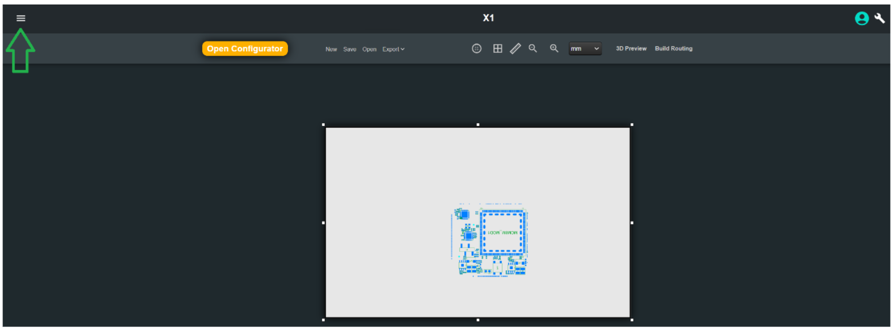
Click on the hamburger sign to show modules which are implementing selected functions.
White rectangle indicates initial area of the board.
Computer and its support components are already placed as shown on the board.
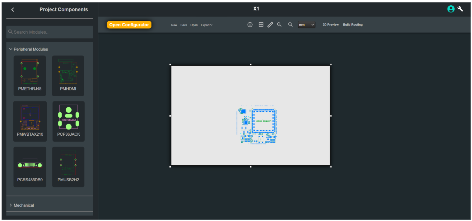
Functions you selected are not yet placed, they are shown on the left pane.
Click on each function. It will then be placed on the board, in arbitrary location.
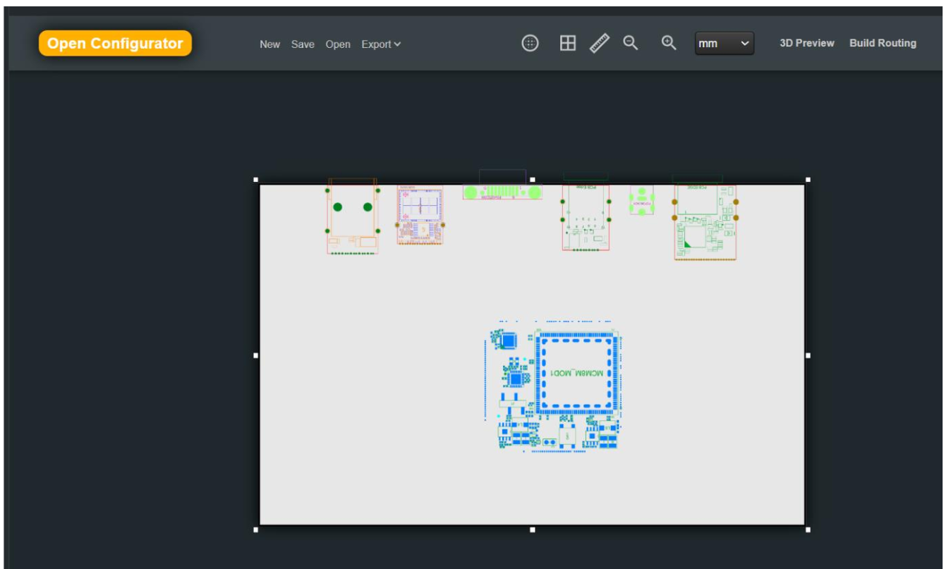
Now you can resize the board as you wish and drag peripheral functions to the required positions.
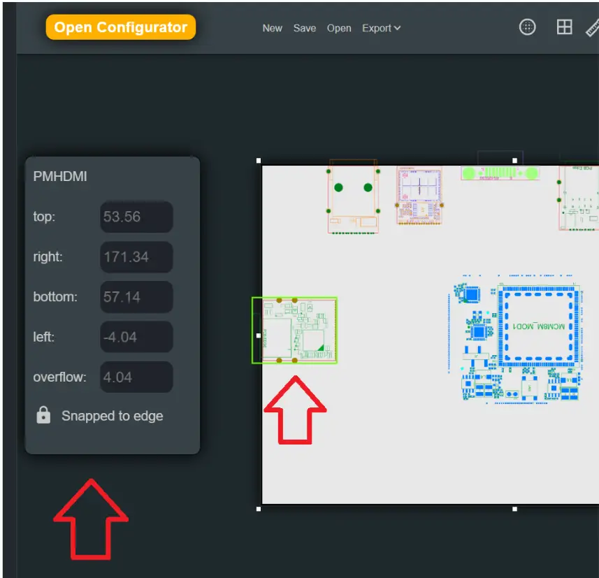
Clicking on the specific module will open menu to control its properties.
Most of the modules have interface connector and therefore by default they are locked to board edge. In this case you can drag the module along all board edges.
You can unlock the module and then drag it into any position on the board. In this case you can also rotate the module. Click on the module and then right-click the mouse to open rotation menu.
Additional tools are available on the top bar, to measure size, show grid, add mounting holes, etc.
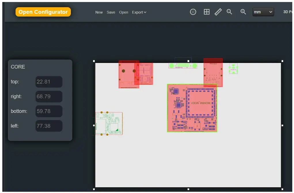
If you will try to position modules too close to each other or over board edge, the system will warn you by colouring the contention in red:
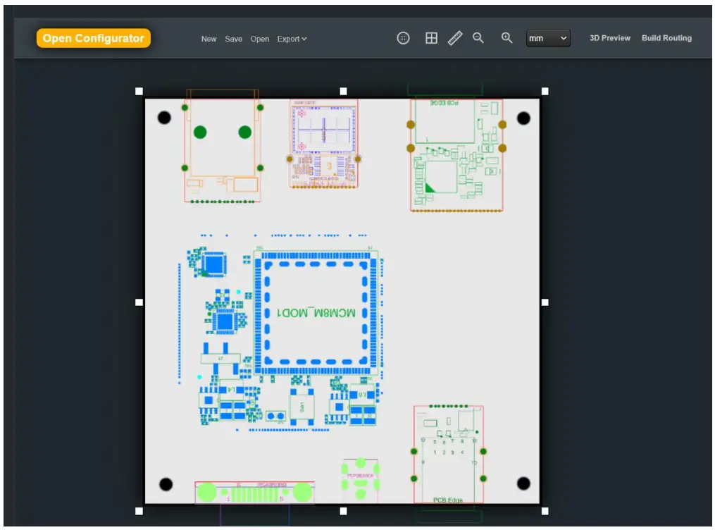
Here is nicely arranged small board with previously selected functions:
To assure mechanical compatibility, click on “Review DXF & 3D” button, and then review mechanical design, either from RoboDesigner application, or download files and review them with other tools.
Once you are satisfied with functional content and mechanical design, click on “Ask to Manufacture” button. The application will then check if it is possible manufacture PCB (printed circuit board) for your design. It will perform initial check that signals routing is possible.
During the process it will look something like this:
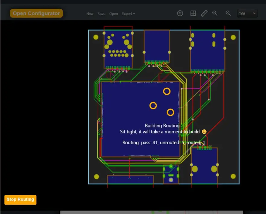
The process is fully automated, you just have to wait. It will end up with one of two possible results:
- The routing is possible and therefore manufacturing is possible. In this case you will be forwarded to ordering page.
- The routing cannot be done. In this case go back to layout designer and try one of following solutions:
• Move peripheral modules to different position, which may help router to resolve interconnection.
• Try rotating the computer module. (click on the module and then right-click mouse)
• Increase board size
• Remove some of functions
Note that cases when routing cannot be accomplished are very rare. Usually, above-mentioned solutions are not required.
Tips and Recommendations
- On initial order Compulab will manufacture and supply two prototype boards. We strongly recommend to test prototype boards before ordering more. After approval of prototype, additional boards can be manufactured relatively quickly.
- If required function is missing in module’s library or if you need different computer, contact Compulab sales. Compulab offers design service for these.
- Accessories, such as WiFi antennas, mounting standoffs or AC to DC adapters can be ordered from Compulab.
Documents / Resources
 |
Compulab Compulab Robo Designer [pdf] User Guide Compulab Robo Designer, Robo Designer, Designer |