AXXESS AXDIS-GMLN29 Data Interface with SWC
Product Specifications
- Model: AXDIS-GMLN29
- Compatibility: GM Data Interface with SWC 2006-Up
- Applications: Various Buick, Cadillac, Chevrolet, GMC, Hummer, Pontiac, Saturn, Suzuki models
Product Usage Instructions
Installation Instructions
Before starting the installation process, make sure to visit AxxessInterfaces.com for the most recent vehicle-specific applications.
Important Note: Disconnect the negative battery terminal with the key out of the ignition before installing the product. Ensure all connections, especially airbag indicator lights, are plugged in before reconnecting the battery or cycling the ignition to test the product. Refer to aftermarket radio instructions as well.
Applications for AXDIS-GMLN29
The AXDIS-GMLN29 is compatible with a range of vehicles including Buick Enclave, Cadillac DTS, Chevrolet Avalanche, GMC Acadia, Hummer H2, Pontiac Torrent, and more. Ensure to check the specific model and year compatibility.
Connections
The interface is designed to work with non-amplified, analog amplified, or digital amplified models. Follow the instructions carefully based on your vehicle’s amplification type to avoid sound issues. If unsure about your vehicle’s amplifier type, contact your local dealership for clarification.
FAQ
Q: How do I know if my vehicle is factory amplified or not?
A: To determine if your vehicle is factory amplified, check the Service Parts Identification sticker located in the glove box for RPO codes Y91, STZ, or others mentioned in the manual. These codes indicate the presence of a digital amplifier in your vehicle.
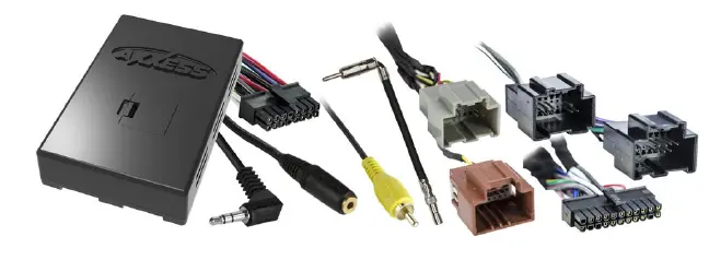
INTERFACE COMPONENTS
- AXDIS-GMLN29 interface
- AXDIS-GMLN29 harness
- Female 3.5mm connector with stripped leads
- 16-pin harness with stripped leads
- RSE harness
- Backup camera harness
- 4-pin to 4-pin resistor pad harness
- Antenna adapter
TOOLS REQUIRED
- Wire cutter
- Crimp tool
- Solder gun
- Tape
- Connectors (example: butt-connectors, bell caps, etc.)
- Small flat-blade screwdriver
APPLICATIONS
See inside front cover
GM Data Interface with SWC 2006-Up
Visit AxxessInterfaces.com for up-to-date vehicle specific applications.
INTERFACE FEATURES
- Designed for non-amplified, or analog/digital amplified models
- Provides accessory power (12-volt 10-amp)
- Retains R.A.P. (Retained Accessory Power)
- Provides NAV outputs (parking brake, reverse, speed sense)
- Retains audio controls on the steering wheel
- Retains balance and fade (excluding digital amplified models)
- Retains RSE (Rear Seat Entertainment)
- Retains chimes
- Retains OnStar® / OE Bluetooth
- Adjustable OnStar® level
- Retains the factory AUX-IN jack
- Retains the factory backup camera
- Retains SAT (Satellite Radio)
- Includes an antenna adapter
- Micro-B USB updatable
MetraOnline.com may be used www.MetraOnline.com Product Info to assist with dash assembly instructions. Simply enter your Year, Make, Model vehicle into the vehicle fit guide and look for the Dash Kit Installation Instructions.

ATTENTION: With the key out of the ignition, disconnect the negative battery terminal before installing this product. Ensure that all installation connections, especially the air bag indicator lights, are plugged in before reconnecting the battery or cycling the ignition to test this product.
NOTE: Refer also to the instructions included with the aftermarket radio.
APPLICATIONS FOR AXDIS-GMLN29
BUICK
- Enclave…………………………………………2008-2017
- Lucerne…………………………………………2006-2011
CADILLAC
- DTS †……………………………………………..2006-2011
- Escalade †……………………………………..2007-2014
- SRX †……………………………………………..2007-2009
CHEVROLET
- Avalanche *Δ……………………………….2007-2013
- Captiva Sport…………………………………2012-2015
- Cheyenne (IOB)……………………………..2016-2018
CHEVROLET (CONT)
- Cheyenne (no RPO)……………………….2012-2014
- Equinox…………………………………………2007-2009
- Express ‡……………………………………….2008-2023
- Impala…………………………………………..2006-2013
- Monte Carlo…………………………………..2006-2007
- Silverado *Δ…………………………………2007-2013
- Spark (IOB) …………………………………..2016-2018
- Suburban **Δ……………………………….2007-2014
- Tahoe **Δ…………………………………….2007-2014
- Traverse………………………………………..2009-2017
GMC
- Acadia…………………………………………..2007-2016
- Savana ‡………………………………………..2008-2023
- Sierra 2500/3500 *Δ……………………..2014
- Sierra *Δ………………………………………2007-2013
- Yukon/Denali / XL **Δ…………………..2007-2014
HUMMER
H2 †……………………………………………….2008-2009
PONTIAC
- Torrent………………………………………….2007-2009
- Vibe………………………………………………2009
SATURN
- Outlook…………………………………………2007-2009
- Vue……………………………………………….2007-2009
SUZUKI
XL-7………………………………………………2007-2009
- These vehicles have a digital amp option. Please reference the “Service Parts Identification” sticker located in the glove box for the RPO code Y91. If Y91 is present, then the vehicle is equipped with a digital amplifier.
- These vehicles have a digital amp option. Please reference the “Service Parts Identification” sticker located in the glove box for the RPO code STZ or Y91. If STZ or Y91 is present, then the vehicle is equipped with a digital amplifier.
- † These vehicles are standard for a digital amplifier.
- ‡ For 2013-2015 models equipped with NAV use the AXDIS-GMLN44.
For 2012-up models equipped with NAV use the AXDIS-GMLN44.
CONNECTIONS
Attention! This interface will work with models that are either non-amplified, analog amplified, or digital amplified. Please follow the instructions carefully for your model vehicle. Failure to do so will result in either no sound, or low sound. If you are unsure if your vehicle is factory amplified or not, please contact your local dealership.
For Models without an Amplifier
From the 16-pin harness with stripped leads to the aftermarket radio
- Connect the Red wire to the accessory wire.
- Connect the Blue/White wire to the power antenna wire.
- If the aftermarket radio has an illumination wire, connect the Orange/White wire to it.
- If the aftermarket radio has a mute wire, connect the Brown wire to it. If the mute wire is not connected, the radio will turn off when OnStar®is activated.
- Connect the Gray wire to the right front positive speaker output.
- Connect the Gray/Black wire to the right front negative speaker output.
- Connect the White wire to the left front positive speaker output.
- Connect the White/Black wire to the left front negative speaker output.
The following (3) wires are only for multimedia/navigation radios that require these wires.
- Connect the Blue/Pink wire to the VSS/speed sense wire.
- Connect the Green/Purple wire to the reverse wire.
- Connect the Light Green wire to the parking brake wire
- Tape off and disregard the following (4) wires, they will not be used in this application: Green, Green/Black, Purple and Purple/Black.
From the AXDIS-GMLN29 Harness to the Aftermarket Radio
- Connect the Black wire to the ground wire.
- Connect the Yellow wire to the battery wire.
- Cut off the resistors from the Green, Green/Black, Purple, and Purple/Black wires below the heat shrink.
- Connect the Green wire to the left rear positive speaker output.
- Connect the Green/Black wire to the left rear negative speaker output.
- Connect the Purple wire to the right rear positive speaker output.
- Connect the Purple/Black wire to the right rear negative speaker output.
- Ensure the (2) 4-pin Molex connectors are connected together.
Note: The 4-pin to 4-pin resistor pad harness will not be used in this application. - The Black/Yellow wire is used for OnStar® level adjustment for models that do not come equipped with steering wheel controls. Refer to the OnStar® level Adjustment section for further instructions.
- Connect the Red and White RCA jacks to the audio AUX-IN jacks of the aftermarket radio.
- Disregard the DIN jack and Red wire.
Note: The relay attached to the AXDIS-GMLN29 harness is only for audible turn signal clicks. No extra steps are required to retain this feature, so leave the relay as-is.
Continue to 3.5mm jack steering wheel control retention
Attention! This interface will work with models that are either non-amplified, analog amplified, or digital amplified. Please follow the instructions carefully for your model vehicle. Failure to do so will result in either no sound, or low sound. If you are unsure if your vehicle is factory amplified or not, please contact your local dealership.
For Models with an Analog Amplifier
From the 16-pin harness with stripped leads to the aftermarket radio
- Connect the Red wire to the accessory wire.
- Connect the Blue/White wire to the amp turn on wire. This wire must be connected to hear sound from the factory amplifier.
- If the aftermarket radio has an illumination wire, connect the Orange/White wire to it.
- If the aftermarket radio has a mute wire, connect the Brown wire to it. If the mute wire is not connected, the radio will turn off when OnStar® is activated.
- Connect the Gray wire to the right front positive speaker output.
- Connect the Gray/Black wire to the right front negative speaker output.
- Connect the White wire to the left front positive speaker output.
- Connect the White/Black wire to the left front negative speaker output.
The following (3) wires are only for multimedia/navigation radios that require these wires.
- Connect the Blue/Pink wire to the VSS/speed sense wire.
- Connect the Green/Purple wire to the reverse wire.
- Connect the Light Green wire to the parking brake wire
- Tape off and disregard the following (4) wires, they will not be used in this application: Green, Green/Black, Purple, Purple/Black
From the AXDIS-GMLN29 harness to the aftermarket radio
- Connect the Black wire to the ground wire.
- Connect the Yellow wire to the battery wire.
- Connect the Green wire to the left rear positive speaker output.
- Connect the Green/Black wire to the left rear negative speaker output.
- Connect the Purple wire to the right rear positive speaker output.
- Connect the Purple/Black wire to the right rear negative speaker output.
- Disconnect the (2) 4-pin Molex connectors, and then attach the 4-pin to 4-pin resistor pad harness.
- The Black/Yellow wire is used for OnStar® level adjustment for models that do not come equipped with steering wheel controls. Refer to the OnStar® level Adjustment section for further instructions.
- Connect the Red and White RCA jacks to the audio AUX-IN jacks of the aftermarket radio.
- Disregard the DIN jack and Red wire.
Note: The relay attached to the AXDIS-GMLN29 harness is only for audible turn signal clicks. No extra steps are required to retain this feature, so leave the relay as-is.
Continue to 3.5mm jack steering wheel control retention
Attention! This interface will work with models that are either non-amplified, analog amplified, or digital amplified. Please follow the instructions carefully for your model vehicle. Failure to do so will result in either no sound, or low sound. If you are unsure if your vehicle is factory amplified or not, please contact your local dealership.
For Models with a Digital Amplifier
From the 16-pin harness with stripped leads to the aftermarket radio
- Connect the Red wire to the accessory wire.
- Connect the Blue/White wire to the amp turn on wire. This wire must be connected to hear sound from the factory amplifier.
- If the aftermarket radio has an illumination wire, connect the Orange/White wire to it.
- If the aftermarket radio has a mute wire, connect the Brown wire to it. If the mute wire is not connected, the radio will turn off when OnStar® is activated.
- Connect the Gray wire to the right front positive speaker output.
- Connect the Gray/Black wire to the right front negative speaker output.
- Connect the White wire to the left front positive speaker output.
- Connect the White/Black wire to the left front negative speaker output.
- Connect the Green wire to the left rear positive speaker output.
- Connect the Green/Black wire to the left rear negative speaker output.
- Connect the Purple wire to the right rear positive speaker output.
- Connect the Purple/Black wire to the right rear negative output.
The following (3) wires are only for multimedia/navigation radios that require these wires.
- Connect the Blue/Pink wire to the VSS/speed sense wire.
- Connect the Green/Purple wire to the reverse wire.
- Connect the Light Green wire to the parking brake wire
From the AXDIS-GMLN29 harness to the aftermarket radio
- Connect the Black wire to the ground wire.
- Connect the Yellow wire to the battery wire.
- Ensure the (2) 4-pin Molex connectors are connected together.
Note: The 4-pin to 4-pin resistor pad harness will not be used in this application. - The Black/Yellow wire is used for OnStar® level adjustment for models that do not come equipped with steering wheel controls. Refer to the OnStar® level Adjustment section for further instructions.
- Tape off and disregard the following (4) wires, they will not be used in this application: Green, Green/Black, Purple, Purple/Black.
- Connect the Red and White RCA jacks to the audio AUX-IN jacks of the aftermarket radio.
- Disregard the DIN jack and Red wire.
Note: The relay attached to the AXDIS-GMLN29 harness is only for audible turn signal clicks. No extra steps are required to retain this feature, so leave the relay as-is.
Continue to 3.5mm jack steering wheel control retention
3.5mm Jack Steering Wheel Control Retention
- The 3.5mm jack is to be used to retain audio controls on the steering wheel.
- For the radios listed below, connect the included female 3.5mm connector with stripped leads onto the male 3.5mm SWC jack from the AXDIS-GMLN29 harness. Any remaining wires tape off and disregard.
- Eclipse: Connect the steering wheel control wire, normally Brown, to the Brown/White wire of the connector. Then connect the remaining steering wheel control wire, normally Brown/White, to the Brown wire of the connector.
- Metra OE: Connect the steering wheel control Key 1 wire (Gray) to the Brown wire.
- Kenwood or select JVC with a steering wheel control wire: Connect the Blue/Yellow wire to the Brown wire.
Note: If your Kenwood radio auto detects as a JVC, manually set the radio type to Kenwood. See the instructions under changing radio type. - XITE: Connect the steering wheel control SWC-2 wire from the radio to the Brown wire.
- Parrot Asteroid Smart or Tablet: Connect the 3.5mm jack into the AXSWCH-PAR (sold separately), and then connect the 4-pin connector from the AXSWCH-PAR into the radio. Note: The radio must be updated to rev. 2.1.4 or higher software.
- Universal “2 or 3 wire” radio: Connect the steering wheel control wire, referred to as Key-A or SWC-1, to the Brown wire of the connector. Then connect the remaining steering wheel control wire, referred to as Key-B or SWC-2, to the Brown/White wire of the connector. If the radio comes with a third wire for ground, disregard this wire.
Note: After the interface has been programmed to the vehicle, refer to the manual provided with the radio for assigning the SWC buttons. Contact the radio manufacturer for more information. - For all other radios: Connect the 3.5mm jack from the AXDIS-GMLN29 harness into the jack on the aftermarket radio designated for an external steering wheel control interface. Please refer to the aftermarket radios manual if in doubt as to where the 3.5mm jack goes to.
- For the radios listed below, connect the included female 3.5mm connector with stripped leads onto the male 3.5mm SWC jack from the AXDIS-GMLN29 harness. Any remaining wires tape off and disregard.
Backup Camera and RSE Harness (if applicable)
- If retaining the factory backup camera, connect the Yellow RCA jack to the backup camera input of the aftermarket radio.
- If retaining the rear seat entertainment system:
- Connect the Black wire with a ring terminal to the chassis of the aftermarket radio.
- From the RCA jacks labeled “FROM REAR A/V INPUT” to the A/V input of the aftermarket radio:
- Connect the Yellow RCA jack to the video in.
- Connect the Red and White RCA jacks to the audio in.
- From the RCA jacks labeled “TO OVERHEAD SCREEN” to the A/V output of the aftermarket radio:
- Connect the Yellow RCA jack to the video out.
- Connect the Red and White RCA jacks to the audio out.
INSTALLATION
With the Key in the Off Position
Connect the 16-pin harness with stripped leads, and the AXDIS-GMLN29 harness, into the interface.
Attention! Do not connect the AXDIS-GMLN29 harness to the wiring harness in the vehicle just yet.
Attention! If retaining steering wheel controls, ensure that the jack/wire is connected to the radio before proceeding. If this step is skipped, the interface will need to be reset for the steering wheel controls to function.
PROGRAMMING
For the steps below, the LED located inside the interface can only be seen while active. The interface does not need to be opened to see the LED
- Start the vehicle.
- Connect the AXDIS-GMLN29 harness to the wiring harness in the vehicle.
- The LED will initially turn on solid Green, then turn off for a few seconds while it auto detects the radio installed.
- The LED will then flash Red up to (24) times indicating which radio is connected to the interface, and then turn off for a couple of seconds. Pay close attention to how many Red flashes there are. This will help in troubleshooting, if need be.
- Refer to the LED feedback section for more information.
- After a couple seconds the LED will turn on solid Red while the interface auto detects the vehicle. The radio will shut off at this point. This process should take 5 to 30 seconds.
- Once the vehicle has been auto detected by the interface, the LED will turn on solid Green, and the radio will come back on, indicating programming was successful.
- Test all functions of the installation for proper operation, before reassembling the dash. If the interface fails to function, refer to Resetting the AXDIS-GMLN29.
Note: The LED will turn on solid Green for a moment, and then turn off under normal operation after the key has been cycled.
ADJUSTMENTS
Audio Level Adjustment (Digital Amplified Models Only)
- With the vehicle and radio turned on, turn the volume up 3/4 of the way.
- With a small flat-blade screwdriver, adjust the potentiometer clockwise to raise the audio level; counterclockwise to lower the audio level.
- Once at a desired level, audio level adjustment is complete.
Chime Level Adjustment
- With the vehicle on, turn it off and leave the keys in ignition. Open the driver’s door; chimes will be heard.
- Wait 10 seconds, and then with a small screwdriver, turn the potentiometer clockwise to raise the chime level; counterclockwise to lower the chime level.
- When the chime is at a desired level, remove the keys from the ignition. This will lock the chime volume at its current level.
OnStar® Level Adjustment
- Press the OnStar® button to activate it.
- While OnStar® is speaking, press the VOLUME UP or VOLUME DOWN button on the steering wheel to raise or lower the OnStar® level.
- If the vehicle does not come equipped with steering wheel controls, locate the Black/Yellow wire on the AXDIS-GMLN29 harness.
- While OnStar® is speaking, tap the Black/Yellow wire to ground. Once the OnStar® level is set, it will stay at that level until the Black/Yellow wire is tapped to ground again.
EXTRA FEATURES
AUX-IN, RSE and SAT
If the vehicle is equipped with AUX-IN, rear seat entertainment, or satellite radio, the AXDIS-GMLN29 can retain these features.
Notes When Retaining AUX-IN
- The AUX-IN jack can only be used if it is a stand-alone AUX-IN jack.
- If the vehicle comes equipped with an AUX-IN jack and a USB port, neither can be retained.
- Change the source of the radio to AUX-IN; satellite radio will start playing.
- The display in the driver’s information center will display the satellite radio information.
- To access advanced features of the satellite radio, press and hold the SOURCE button on the steering wheel for 3 seconds.
- Listed below are the functions of the steering wheel control buttons while accessing the advanced features:
- SEEK UP – Scrolls menu up.
- SEEK DOWN – Scrolls menu down.
- VOLUME UP- Enter
- Listed below are the advanced menu options:
- Show Text – Exits menu.
- Set Tuning Mode – Allows the user to select tuning by either a preset, or a channel.
- Set Preset – Allows the user to program presets.
- Set Display – Allows the user to choose which satellite radio information should be displayed.
- Set Satellite Radio Text Mode – Allows the user to set the display length of the satellite radio information. Options are; On, Off, or 5 seconds (default is 5 seconds).
- To access AUX-IN or rear seat entertainment, press and hold the SOURCE button on the steering wheel for 2 seconds. This will switch to the next source available. Each time the SOURCE button is pressed for 2 seconds, the source will change. The sequence of sources are SAT/RSE/AUX-IN. The driver’s information center will provide a visual confirmation of which source is active.
STEERING WHEEL CONTROL SETTINGS
LED Feedback
- The (24) Red LED flashes represent a different radio manufacturer for the AXDIS-GMLN29 interface to detect.
- For example, if you are installing a JVC radio, the AXDIS-GMLN29 interface will flash Red (5) times, then stop.
- At right is the LED Feedback Legend, which indicates the flash count of the radio manufacturer.
LED Feedback Legend
| Flash Count | Radio |
| 1 | Eclipse (type 1) † |
| 2 | Kenwood ‡ |
| 3 | Clarion (type 1) † |
| 4 | Sony / Dual |
| 5 | JVC |
| 6 | Pioneer / Jensen |
| 7 | Alpine * |
| 8 | Visteon |
| 9 | Valor |
| 10 | Clarion (type 2) † |
| 11 | Metra OE |
| 12 | Eclipse (type 2) † |
| Flash Count | Radio |
| 13 | LG |
| 14 | Parrot ** |
| 15 | XITE |
| 16 | Philips |
| 17 | TBA |
| 18 | JBL |
| 19 | Insane |
| 20 | Magnadyne |
| 21 | Boss |
| 22 | Axxera |
| 23 | Axxerra (type 2) |
| 24 | Alpine (type 2) |
KEYNOTES
- If the AXDIS-GMLN29 flashes RED (7) times, and an Alpine radio is not installed, that means there is an open connection not accounted for. Verify that the 3.5mm jack is connected to the correct steering wheel jack/wire in the radio.
- The AXSWCH-PAR is required (sold separately). Also, the software in the radio must be rev. 2.1.4 or higher.
- † If a Clarion or Eclipse radio is installed and the steering wheel controls do not function, change the radio to Clarion (type 2) or Eclipse (type 2) respectively. If the steering wheel controls still do not function, refer to the Changing Radio Type document available at axxessinterfaces.com .
- ‡ If a Kenwood radio is installed and the LED feedback flashes (5) times instead of (2), manually change the radio type to Kenwood. To do this, refer to the Changing Radio Type document on next page, also available at axxessinterfaces.com .
Attention: The Axxess Updater App can also be used to program the following (3) sub-sections as well, pending that the interface has been initialized and programmed.
Changing Radio Type
If the LED flashes do not match the radio you have connected, you must manually program the AXDIS-GMLN29 to tell it what radio it is connected to.
- After (3) seconds of turning the key on, press and hold the Volume-Down button on the steering wheel until the LED in the AXDIS-GMLN29 goes solid.
- Release the Volume-Down button; the LED will go out indicating we are now in Changing Radio Type mode.
- Refer to the Radio Legend to know which radio number you would like to have programmed.
- Press and hold the Volume-Up button until the LED goes solid, and then release. Repeat this step for the desired radio number you have selected.
- Once the desired radio number has been selected, press and hold the Volume-Down button on the steering wheel until the LED goes solid. The LED will remain on for about (3) seconds while it stores the new radio information.
- Once the LED goes off, the Changing Radio Type mode will then end. You can now test the steering control wheel controls.
Note: If at any time the user fails to press any button for a period longer than (10) seconds, this process will abort.
Radio Legend
| Flash Count Radio Legend | |
| 1. Eclipse (type 1) | 13. LG |
| 2. Kenwood | 14. Parrot |
| 3. Clarion (type 1) | 15. XITE |
| 4. Sony / Dual | 16. Philips |
| 5. JVC | 17. TBA |
| 6. Pioneer / Jensen | 18. JBL |
| 7. Alpine | 19. Insane |
| 8. Visteon | 20. Magnadyne |
| 9. Valor | 21. Boss |
| 10. Clarion (type 2) | 22. Axxera |
| 11. Metra OE | 23. Axxerra (type 2) |
| 12. Eclipse (type 2) | 24. Alpine (type 2) |
Remapping the Steering Wheel Control Buttons
Let’s say you have AXDIS-GMLN29 initialized and you want to change the button assignment for the steering wheel control buttons. For example, you would like Seek-Up to become Mute. Follow the steps below to remap the steering wheel control buttons
- Ensure the AXDIS-GMLN29 is visible so you can see the LED flashes to confirm button recognition. Tip: Turning the radio off is recommended.
- Within the first twenty seconds of turning the ignition on, press and hold the Volume-Up button on the steering wheel until the LED goes solid.
- Release the Volume-Up button, the LED will then go out; The Volume-Up button has now been programmed.
- Follow the list in the Button Assignment Legend to reference the order in which the steering wheel control buttons need to be programmed.
Note: If the next function on the list is not on the steering wheel, press the Volume-Up button for (1) second until the LED comes on, and then release the Volume-Up button. This will tell the AXDIS-GMLN29 that this function is not available and it will move on to the next function. - To complete the remapping process, press and hold the Volume-Up button on the steering wheel until the LED in the AXDIS-GMLN29 goes out.
Button Assignment Legend
- Volume-Up
- Volume-Down
- Seek-Up/Next
- Seek-Down/Prev
- Source/Mode
- Mute
- Preset-Up
- Preset-Down
- Power
- Band
- Play/Enter
- PTT (Push to Talk) *
- On-Hook *
- Off-Hook *
- Fan-Up *
- Fan-Down *
- Temp-Up *
- Temp-Down *
* Not applicable in this application
Note: Not all radios will have all of these commands. Please refer to the manual provided with the radio, or contact the radio manufacturer for specific commands recognized by that particular radio.
Dual Assignment Instructions (Long Button Press)
The AXDIS-GMLN29 has the capability to assign (2) functions to a single button, except Volume-Up and Volume-Down. Follow the steps below to program the button(s) to your liking.
Note: Seek-Up and Seek-Down come pre-programmed as Preset-Up and Preset-Down for a long button press.
- Turn on the ignition but do not start the vehicle.
- Press and hold down the steering wheel control button that you want to assign a long press function to for about (10) seconds, or until the LED flashes rapidly. At this point release the button; the LED will then go solid.
- Press and release the Volume-Up button the number of times corresponding to the new button number selected. Refer to the Dual Assignment Legend. The LED will flash rapidly while the Volume-Up button is being pressed, and then go back to a solid LED once released. Go to the next step once the Volume-Up button has been pressed the desired number of times.
- To store the long press button in memory, press the button that you assigned a long press button to (the button held down in Step 2). The LED will now go off indicating the new information has been stored.
Dual Assignment Legend
- Not allowed
- Not allowed
- Seek-Up/Next
- Seek-Down/Prev
- Mode/Source
- ATT/Mute
- Preset-Up
- Preset-Down
- Power
- Band
- Play/Enter
- On-Hook
- Off-Hook
- Fan-Up *
- Fan-Down *
- Temp-Up *
- Temp-Down *
- PTT*
Not applicable in this application
Caution: If more than (10) seconds elapses between pressing the Volume-Up button, this procedure will abort, and the LED will go out.
Note: These steps must be repeated for each button you would like to assign a dual purpose feature to. To reset a button back to its default state, repeat Step 1, and then press the Volume-Down button. The LED will go out, and the long press mapping for that button will be erased.
TROUBLESHOOTING
Resetting the AXDIS-GMLN29
- The Blue reset button is located inside the interface, between the two connectors. The button is accessible outside the interface, no need to open the interface.
- Press and hold the reset button for two seconds, and then let go to reset the interface.
- Refer to Programming section from this point.
Having difficulties? We’re here to help.
- Contact our Tech Support line at
- 386-257-1187
- Or via email at
- techsupport@metra-autosound.com
Tech Support Hours (Eastern Standard Time)
- Monday – Friday: 9:00 AM – 7:00 PM
- Saturday: 10:00 AM – 5:00 PM
- Sunday: 10:00 AM – 4:00 PM
Metra recommends MECP certified technicians
Documents / Resources
 |
AXXESS AXDIS-GMLN29 Data Interface with SWC [pdf] Installation Guide AXDIS-GMLN29, AXDIS-GMLN29 Data Interface with SWC, Data Interface with SWC, Interface with SWC, SWC |