ALLEGRO microSystems CT220 Linear Magnetic Sensor

- Input Operating Voltage: 3V – 3.3V
- Cutoff Frequency (3 dB): 10 Hz
- Operating Temperature: Min. 3°C, Typ. 3.3°C
- Gain: 300 mV/V/mT
Product Information
The CTD221-BB-1.5 Evaluation Board is designed for evaluating the CT220BMV-IS5 current sensor. It provides connections and configuration options for monitoring the sensor output.
Product Usage Instructions
Overview of Connections and Configuration
The evaluation board is powered by connecting a DV bias voltage between the VCC and GND pins. The OUT pin should be connected to a digital voltmeter or oscilloscope for output monitoring.
Detailed Steps
- Connect DV bias voltage between VCC and GND pins.
- Connect OUT pin to a digital voltmeter or oscilloscope.
- Refer to the product datasheet for detailed pin functionality.
- Q: How should I power the evaluation board?
- A: Power the board by connecting a DV bias voltage between the VCC and GND pins.
- Q: What should I connect to monitor the output?
- A: Connect the OUT pin to a digital voltmeter or oscilloscope for output monitoring.
- Q: Where can I find detailed pin information?
- A: Refer to the product datasheet for comprehensive pin functionality details.
DESCRIPTION
The CTD221-BB-1.5 evaluation board is designed to dem-onstrate the current sensing capabilities of the CT220 linear magnetic sensor from Allegro MicroSystems. The CT220 is a contactless current sensor based on XtremeSense™ tunnel magnetoresistance (TMR) technology. It features a full-bridge configuration comprising four TMR elements monolithically integrated with active CMOS circuitry, allowing it to have high resolution and low noise in a small-package footprint. This user guide describes how to connect and use the CTD221-BB-1.5 evaluation board.
FEATURES
- Field range: ±1.5 mT
- Gain: 300 mV/V/mT
- 3 V to 5 V power supply
EVALUATION BOARD CONTENTS
CTD221-BB-1.5 evaluation board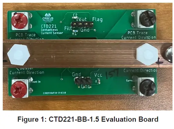
Table 1: CTD221-BB-1.5 Evaluation Board Configurations
| Configuration Name | Part Number | B-Field | Gain |
| CTD221-BB-1.5 | CT220BMV-IS5 | ±1.5 mT | 300 mV/V/mT |
Table 2: General Specifications
Specification |
Min. | Typ. | Max. | Units |
| Input Operating Voltage | 3 | 3.3 | 5 | V |
| Cutoff Frequency (3 dB) | – | 10 | – | kHz |
| Operating Temperature | –40 | – | 85 | °C |
USING THE EVALUATION BOARD
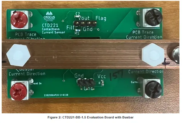
This section provides an overview of the connections and con-figuration options of the CTD221-BB-1.5 evaluation board. Each group of connections highlighted in Figure 2 has a detail section below. The product datasheet contains detailed information about the use and functionality of each pin and should be consulted for more-detailed information than is contained in this user guide.
The evaluation board is powered by connecting a DV bias voltage between the VCC and GND pins on the PCB. The OUT pin of the PCB should be connected to a digital voltmeter (DVM) or an oscilloscope to monitor the output of the CT220 current sensor. The data present in this section is for a 5 V bias voltage.
Low-Current Mode
In low-current mode, the current passes through a 0.9 mm-wide trace on the top layer of the PCB. This mode can be used to measure currents in the range of ±3.85 A. Clearance between the trace and IC pads is 0.35 mm, which provides isolation of 1 kV between the current trace and the SOT23 pins. In addition to the excellent linearity across temperature, the high signal-to-noise ratio (SNR) of the CT220 enables it to measure extremely low currents. The CTD221 can detect currents as low as 5 mA.
Medium-Current Mode
In medium-current mode, the current passes through a 2 mm-wide trace on the bottom layer of the PCB. This wider trace (compared to low-current mode) allows for a larger current to be detected. This mode can be used to measure currents of ±10 A, with the ability to resolve in 10 mA steps. The isolation of the CT220 for this configuration is 5.1 kVrms because the distance between the bottom trace and the SOT23 pins is 1.6 mm.
High-Current Mode
The high-current mode is used for applications involving currents too large to pass through the PCB traces. In this mode, the current is passed through a copper busbar. The busbar is 1/2” wide and 1/16” thick. The user has the flexibility to adjust the distance of the busbar from the top surface of the PCB using plastic, temper-ature-resistant washers. The CTD221 evaluation board is shipped with spacers to maintain a 4 mm gap between the PCB and the busbar. With this configuration, the CTD221 can be used to measure currents in the full range of 50 A and to measure currents in the range of ±50 A with a 50 mA resolution. With a spacing distance of 4 mm between the CT220 and the busbar, the isolation voltage exceeds 5.1 kVrms in the high-current mode.
SCHEMATIC
The schematic of the CTD221-BB-1.5 evaluation board is shown in Figure 3.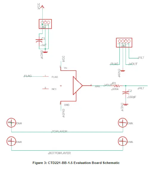
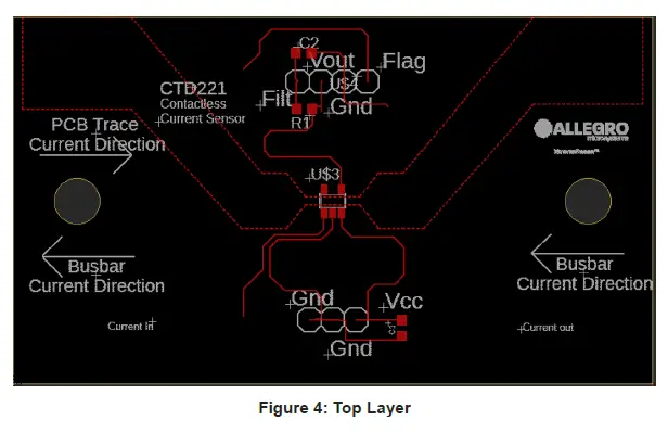
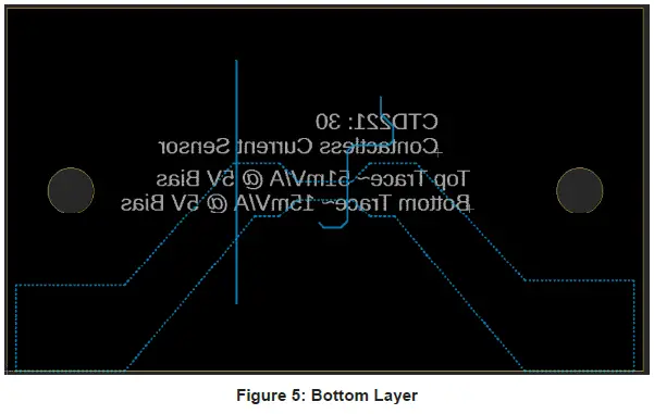
LAYOUT
The top and bottom layers of the CTD221-BB-1.5 evaluation board are shown in Figure 4 and Figure 5.
BILL OF MATERIALS
Table 3: CT220BMV-IS5 Version Evaluation Board Bill of Materials
| Designator | Quantity | Description | Manufacturer | Manufacturer Part Number |
| ELECTRICAL COMPONENTS | ||||
| – | 1 | CTD221-BB-1.5 EVAL PCB | Allegro MicroSystems | – |
| U$3 | 1 | CT220 Sensor | Allegro MicroSystems | – |
| FLAG, GND, VOUT, FILTER | 1 | Male Header Connectors | Samtec | TSW-104-07-F-S |
| GND, VCC | 1 | Male Header Connectors | Samtec | TSW-102-07-F-S |
| C1 | 1 | Capacitor, Ceramic, 1.0 µF, 25 V, 10% X7R 0603 | TDK | MSAST168SB7105KTNA01 |
| C2 | 1 | Capacitor, Ceramic, 150 pF, 1 kV, 10% X5F 0603 | Vishay | 562R10TST15 |
| R1 | 1 | Resistor, 105 kΩ, 1/10 W, 1% 0603 | Vishay | TNPW0603105KBEEA |
| OTHER COMPONENTS | ||||
| – | 1 | Busbar (1/2” width, 1/16” thick) | – | – |
| – | 4 | Connector Heads | Keystone Electronics | 36-7701-ND |
| – | 4 | M3x6mm Metal Screws for Connector Heads | UXCell | a15120300ux0251 |
| – | 2 | Plastic High Temperature Screws for Busbar | Misumi | SPS-M5X15-C |
| – | 2 | Plastic High Temperature Nuts for Busbar | Misumi | SPS-M5-N |
| – | 2 | Plastic High Temperature Washers for Busbar | Misumi | SPS-6-W |
RELATED LINKS
CT220 Product Webpage: https://www.allegromicro.com/en/products/sense/current-sensor-ics/sip-package-zero-to-thousand-amp-sensor-ics/ct220
Revision History
| Number | Date | Description |
| – | September 11, 2024 | Initial release |
Copyright 2024, Allegro MicroSystems.
- Allegro MicroSystems reserves the right to make, from time to time, such departures from the detail specifications as may be required to permit improvements in the performance, reliability, or manufacturability of its products.
- Before placing an order, the user is cautioned to verify that the information being relied upon is current.
- Allegro’s products are not to be used in any devices or systems, including but not limited to life support devices or systems, in which a failure of Allegro’s product can reasonably be expected to cause bodily harm.
- The information included herein is believed to be accurate and reliable. However, Allegro MicroSystems assumes no responsibility for its use; nor for any infringement of patents or other rights of third parties which may result from its use.
Copies of this document are considered uncontrolled documents.
- Allegro MicroSystems 955 Perimeter Road
- Manchester, NH 03103-3353 U.S.A.
- www.allegromicro.com
Documents / Resources
 |
ALLEGRO microSystems CT220 Linear Magnetic Sensor [pdf] User Guide CTD221-BB-1.5, CT220BMV-IS5, CT220 Linear Magnetic Sensor, CT220, Linear Magnetic Sensor, Magnetic Sensor, Sensor |


