![]() USER MANUAL
USER MANUAL  MODEL: WP-DEC7
4K AVoIP Decoder
www.kramerav.com
Introduction
Welcome to Kramer Electronics! Since 1981, Kramer Electronics has been providing a world of unique, creative, and affordable solutions to the vast range of problems that confront the video, audio, presentation, and broadcasting professional on a daily basis. In recent years, we have redesigned and upgraded most of our line, making the best even better!
Getting Started
We recommend that you:
- Unpack the equipment carefully and save the original box and packaging materials for possible future shipment.
- Review the contents of this user manual.
![]() Go to www.kramerav.com/downloads/WP-DEC7 to check for up-to-date user manuals, application programs, and to check if firmware upgrades are available (where appropriate).
Go to www.kramerav.com/downloads/WP-DEC7 to check for up-to-date user manuals, application programs, and to check if firmware upgrades are available (where appropriate).
Achieving Best Performance
- Use only good quality connection cables (we recommend Kramer high-performance, high-resolution cables) to avoid interference, deterioration in signal quality due to poor matching, and elevated noise levels (often associated with low quality cables).
- Do not secure the cables in tight bundles or roll the slack into tight coils.
- Avoid interference from neighboring electrical appliances that may adversely influence signal quality.
- Position your Kramer WP-DEC7 away from moisture, excessive sunlight and dust.
Safety Instructions
![]() Caution:
Caution:
- This equipment is to be used only inside a building. It may only be connected to other equipment that is installed inside a building.
- For products with relay terminals and GPI\O ports, please refer to the permitted rating for an external connection, located next to the terminal or in the User Manual.
- There are no operator serviceable parts inside the unit.
![]() Warning:
Warning:
- Use only the power cord that is supplied with the unit.
- To ensure continuous risk protection, replace fuses only according to the rating specified on the product label which is located on the bottom of the unit.
Recycling Kramer Products
The Waste Electrical and Electronic Equipment (WEEE) Directive 2002/96/EC aims to reduce the amount of WEEE sent for disposal to landfill or incineration by requiring it to be collected and recycled. To comply with the WEEE Directive, Kramer Electronics has made arrangements with the European Advanced Recycling Network (EARN) and will cover any costs of treatment, recycling and recovery of waste Kramer Electronics branded equipment on arrival at the EARN facility. For details of Kramer’s recycling arrangements in your particular country go to our recycling pages at www.kramerav.com/quality/environment.
Overview
Congratulations on purchasing your Kramer WP-DEC7 4K AVoIP Decoder, an advanced decoder for streaming 4K@60Hz (4:2:0) video signals, RS-232, or CEC signals via Ethernet over copper cable in unicast (one-to-one) or multicast (one-to-many) configurations.
WP-DEC7 decodes encoded video signal and receives RS-232 or CEC signals.
WP-DEC7 provides high-quality, advanced user-friendly operation and flexible control.
Exceptional Quality
- Video Streaming Transmitter/Receiver – Streams up to 4K@60Hz (4:2:0) resolution signals over a 1G network interface.
- HDR Support – HDR10 up to 4K@30Hz 4:2:2 12bits.
- Streaming Support – Provides unicast and multicast streaming.
- Analog Audio De-embedding – WP-DEC7 extracts the HDMI audio signal or LAN streaming audio and outputs it as balanced analog audio.
- Video Wall Support – WP-DEC7 can create a video wall of up to 16×16 displays.
Advanced and User-friendly Operation
- Convenient and Comprehensive Control – Control the unit using intuitive embedded web pages, Protocol 3000 API commands via Ethernet, or front panel buttons. • PoE Support – Device power is supplied by a PoE (Power over Ethernet) connection from a PoE switch.
- Control Gateway – Through P3K or special TCP connection, remote users can control/communicate with RS-232, or CEC to the connected devices.
- Separate Service LAN Port – A second LAN port is available for physical separation between AV and command streams to improve security and reliability.
Flexible Connectivity
- Analog/embedded audio outputs.
Typical Applications
WP-DEC7 is ideal for the following typical applications:
- Real-time essential installations such as command and control rooms.
- Large scale AV content sharing installations using existing wires and infrastructure in corporate offices and government applications.
- AV distribution systems with one or more sources and multiple displays in schools, universities, and public venues.
Controlling your WP-DEC7
Control your WP-DEC7 via:
- The Ethernet using built-in user-friendly web pages.
- Protocol commands.
Defining WP-DEC7

| # | Feature |
Function |
|
| 1 | HDMI OUT Connector | Connect to an additional WP-DEC7 device to loop the signal, or to connect a local acceptor. | |
| 2 | HDMI LED | Lights Green | A link has been established with an encoder which is transmitting A/V signals. |
| Flashes Green | A signal is established, and a problem is detected. | ||
| 3 | ON LED | Flashes Red | Default IP address is unavailable, device acquiring fallback address in subnet 192.168.0.0/16. ‘ON’ LED flashes continuously in slow 0.5/10sec cadence. |
| Lights Green | Power is on. | ||
| Flashes Green fast | FW is downloaded in the background. | ||
| Flashes Green very fast (for 60sec) | A device identification command is sent (Flag me). | ||
| Lights Yellow | Device falls back to default IP address (192.168.1.40). | ||
| 4 | CH+ / CH-Recessed Buttons | Press to set the channel ID. The channel ID will show in the LCD display. On the US model access to these buttons requires removal of the frame set. |
| 5 | RESET Recessed Button | Press and hold for 10 seconds to reset the device to its factory default values. All LEDs flash. On the US model access to this button requires removal of the frame set. |
| 6 | LCD Display | Displays the channel on which the media is streamed. |
| 7 | LAN MEDIA 1G(PoE) RJ-45 Port |
Unicast: connect for streaming either directly to a decoder or via LAN. Multicast: connect to multiple decoders or connect to one decoder to which multiple decoders are daisy-chained via SERVICE (1G) port. WP-DEC7 is powered by PoE (power over ethernet) delivered through the LAN MEDIA port, unless the optional 20V DC connector is attached. |
| 8 | AUDIO OUT 5-pin Terminal Block Connector |
Connect to a balanced analog stereo audio acceptor. |
| 9 | 20V/1A DC Connector | Connect to the power adapter (optional, purchased separately). |
| 10 | LAN SERVICE 1G RJ-45 Port | Used optionally for physical separation between AV and command streams to separate LAN for security and reliability purposes. |
| 11 | Ring Tongue Terminal Grounding Screw | Connect to a grounding wire (optional). |
| 12 | RS-232 3-pin Terminal Block Connector | Connect to an RS-232 device to use as a Gateway and bi-directional signal extension (even when no AV signal is extended). |
Mounting WP-DEC7
![]() This section provides instructions for mounting WP-DEC7. Before installing, verify that the environment is within the recommended range:
This section provides instructions for mounting WP-DEC7. Before installing, verify that the environment is within the recommended range:
- Operation temperature – 0° to 40°C (32 to 104° F).
- Storage temperature – -40° to +70°C (-40 to +158°F).
- Humidity – 10% to 90%, RHL non-condensing.
![]() Caution:
Caution:
- Mount WP-DEC7 before connecting any cables or power.
![]() Warning:
Warning:
- Ensure that the environment (e.g., maximum ambient temperature & air flow) is compatible for the device.
- Avoid uneven mechanical loading.
- Appropriate consideration of equipment nameplate ratings should be used for avoiding overloading of the circuits.
- Reliable earthing of rack-mounted equipment should be maintained.
- Maximum mounting height for the device is 2 meters.
Insert the device into the in-wall box (first connect the RS-232 and LAN/POE RJ-45
Connector cables and/or power) and connect the parts as shown in the illustration:

![]() DECORA® design frames are included in US-D models.
DECORA® design frames are included in US-D models.
We recommend that you use standard 2 gang in-wall junction boxes (or their equivalent):
- US-D: 2 gang US electrical junction boxes.
- EU: 2 gang in-wall junction box, with a cut-hole diameter of 2x68mm and depth that can fit in both the device and the connected cables (DIN 49073).
- UK: 2 gang in-wall junction box (BS 4662), 135x75mm (W, H) and depth that can fit in both the device and the connected cables.
- EU/UK: 2 gang on-wall junction box (use the recommended Kramer on-wall box available at www.kramerav.com/product/WP-DEC7).
Connecting WP-DEC7
![]() By-default, the WP-DEC7 is powered by PoE (Power over Ethernet). An optional power adapter can be purchased for connecting the product to mains electricity.
By-default, the WP-DEC7 is powered by PoE (Power over Ethernet). An optional power adapter can be purchased for connecting the product to mains electricity.
Always switch off the power to a device before connecting it to your WP-DEC7. After connecting your devices, connect their power and then switch on the power to each device.
In this example, WP-DEC7 is connected to KDS-EN7, but it can be connected to any compatible decoder
 To connect WP-DEC7 as illustrated in the example in Figure 2:
- Connect the LAN MEDIA 1G(PoE) RJ-45 port 7 on the WP-DEC7 to the LAN MEDIA1G(PoE) RJ-45 port on the LAN switch.
- Connect an AV source to the HDMI IN port (for example, a Server or a Media Player) on the encoder. Connect the:
▪ Audio port to the AUDIO 5-pin terminal block.
▪ HDMI port to the HDMI connector. - Connect the HDMI OUT connector 1 on WP-DEC7 to an HDMI acceptor (for example, a display).
- Connect RS-232 3-pin terminal block connectors:
▪ On the encoder, connect the RS-232 port to a laptop/controller.
▪ On the WP-DEC7, connect RS-232 12 to the display.
![]() RS-232 bidirectional signals can be sent between the display and the laptop connected to the HDMI OUT connector on the WP-DEC7.
RS-232 bidirectional signals can be sent between the display and the laptop connected to the HDMI OUT connector on the WP-DEC7.
Connecting the Audio Output
The following are the pinouts for connecting the input/output to a balanced or unbalanced stereo audio acceptor:  Connecting to WP-DEC7 via RS-232
You can connect to WP-DEC7 via an RS-232 connection 12 using, for example, a PC.
WP-DEC7 features an RS-232 3-pin terminal block connector allowing the RS-232 to control WP-DEC7.
Connect the RS-232 terminal block on the rear panel of WP-DEC7 to a PC/controller, as follows:
From the RS-232 9-pin D-sub serial port, connect:
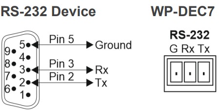
- Pin 2 to the TX pin on the WP-DEC7 RS-232 terminal block
- Pin 3 to the RX pin on the WP-DEC7 RS-232 terminal block
- Pin 5 to the G pin on the WP-DEC7 RS-232 terminal block
Operating and Controlling WP-DEC7
This section describes the following actions:
- Configuring the Network Switch on page 11.
- Configuring the WP-DEC7 on page 11.
- Operating via Ethernet on page 12.
- Connecting the Ethernet Port Directly to a PC on page 12.
Configuring the Network Switch
Before setting the system, make sure that your AV over IP network switch meets the following minimum requirements:
- A PoE (power over ethernet) switch or PoE injector is required to power the WP-DEC7.
If necessary, an optional 20V DC power supply can be used. - Jumbo Frames – On. (at least 8000 bytes).
- IGMP Snooping – On.
- IGMP Querier – On.
- IGMP Immediate/Fast Leave – On.
 WP-DEC7 supports multicast IGMPv2 version.
 - Unregistered Multicast Filtering – On.
Configuring the WP-DEC7
To start operating the WP-DEC7:
- Use the recessed CH+/- buttons 12 to match the channel on which the encoded input is streamed. By default, the WP-DEC7 searches for an encoded stream on channel 1.
- If an encoder source (such as the Error! No document variable supplied. Error! No document variable supplied.) is detected, the HDMI LED lights green. If none is detected, it flashes green.
- If an HDMI acceptor is connected, but no encoded stream is detected, a NO SIGNAL screen will be displayed and the bottom right of the screen will show the device’s firmware version and local IP.
Use the Web UI to configure WP-DEC7 (see Using WP-DEC7 Embedded Web Pages on page 15).
Operating via Ethernet
The WP-DEC7’s embedded Web UI provides high-level configuration options. Access to this UI requires an ethernet connection to the WP-DEC7 and that you identify its IP address.
To identify the device’s IP address, use any of the following methods:
- Connect the WP-DEC7 ethernet port directly to a PC.
For instructions, see Connecting the Ethernet Port Directly to a PC on page 12.
When connected to a PC, the WP-DEC7 is given the default static IP address:
192.168.1.40. If this IP address is already in use, the system will provide a random unique IP in the range of 192.168.X.Y - Connect the Ethernet port of WP-DEC7 to the Ethernet port on a network hub, switch or router using a straight-through cable with RJ-45 connectors.
Make sure your PC is connected to the same LAN as the WP-DEC7.
By default, the WP-DEC7 is DHCP-enabled. Make sure that there is a DHCP server in the network so the device can obtain a valid IP address.
Identify the device’s IP address. This can be achieved by connecting a screen to the WP-DEC7 HDMI port without providing any encoded input. The screen shows the device’s Local IP address at the bottom right.
You can change the Ethernet parameters via the embedded web pages (see Using WP-DEC7 Embedded Web Pages on page 15) . - Use the Kramer KDS-7-MNGR to discover the IP address, see www.kramerav.com/product/KDS-7-MNGR.
Connecting the Ethernet Port Directly to a PC
You can connect the Ethernet port of WP-DEC7 directly to the Ethernet port on your PC using a crossover cable with RJ-45 connectors.
![]() This type of connection is recommended for identifying WP-DEC7 with the factory configured default IP address, 192.168.1.40.
This type of connection is recommended for identifying WP-DEC7 with the factory configured default IP address, 192.168.1.40.
To connect the WP-DEC7 to the Ethernet port, configure your PC as follows:
- Click Start > Settings > Network & Internet.
- Under Advanced network settings, click Change Adapter Options.
- Highlight the network adapter you want to use to connect to the device and click Change settings of this connection.
The Local Area Connection Properties window for the selected network connection appears as shown in Figure 5.
- Highlight either Internet Protocol Version 6 (TCP/IPv6) or Internet Protocol Version 4 (TCP/IPv4) depending on the requirements of your IT system.
- Click Properties.
The Internet Protocol Properties window relevant to your IT system appears as shown in Figure 6 or Figure 7.

- Select Use the following IP Address for static IP addressing and fill in the details as shown in Figure 8.
For TCP/IPv4 you can use any IP address in the range 192.168.1.1 to 192.168.1.255 (excluding 192.168.1.40) that is provided by your IT department.
- Click OK.
- Click Close.
- Continue with Using WP-DEC7 Embedded Web Pages on page 15.
Using WP-DEC7 Embedded Web Pages
WP-DEC7 can be operated remotely using the embedded Web UI pages. Access the Web UI by typing the WP-DEC7’s IP address in a browser and pressing Enter.
The following operating systems and Web browsers are supported:
| Operating Systems | Browser |
| Windows 7 | Chrome Firefox Safari |
| Windows 10 | Chrome Edge Firefox |
| Mac | Safari |
| iOS | Safari |
| Android OS | N/A |
![]() If a web page does not update correctly, clear your Web browser’s cache.
If a web page does not update correctly, clear your Web browser’s cache.
Opening the WP-DEC7 Embedded Web Pages
To Browse the WP-DEC7 Web Pages:
- Open your Internet browser.
- Type the IP number of the device in the Address bar of your browser. To find out the IP address, see Operating via Ethernet on page 12.
For example, the default IP number:
- If your device is password-protected, the Login window appears.
 Enter the Username and Password (admin/admin, by default).
 - The WP-DEC7 Main page (AV Routing tab) opens.

- Select from the pages on the left side of the screen to access options.
The Web UI has six pages (accessed from the menu on the left side):
 Main page: AV routing.
 AV Settings page.
 Device Settings page.
 Control page.
 Diagnostics page.
 About page.
The WP-DEC7 embedded web pages enable performing the following actions:
- Defining and Viewing AV Routing Parameters on page 17.
- Configuring Device Information on page 19.
- Setting the Video Wall on page 20.
- Configuring the Overlay on page 21.
- Defining Video Settings on page 24.
- Setting General Preferences on page 25.
- Managing Network Settings on page 28.
- Defining an NTP Time and Date Server on page 31.
- Configuring WP-DEC7 for HTTPS and 802.1x on page 32.
- Managing User Access on page 34.
- Defining WP-DEC7 Gateway Settings on page 35.
- Viewing WP-DEC7 Status on page 38.
- Viewing WP-DEC7 Connections Status on page 39.
- Viewing the WP-DEC7 Logs on page 40.
- Viewing the About Page on page 41.
Defining and Viewing AV Routing Parameters
To define AV routing settings:
- In the Navigation pane, Select Main>AV Routing. The AV Routing page appears.

- Set the following:
▪ Channel ID: Set Channel ID and click APPLY.
Channel ID defines the device input ID (1 to 999). See also Hiding the Channel Number on page 27.
▪ Channel Name: If necessary, enter the Stream Name and click APPLY.
Stream name is identical to Host name (see Setting General Preferences on page 25) can include up to 24 characters; “-“ and “_” are allowed within the name. by default, the name is the model name and MAC address connected by “-“.
▪ Volume: Use the slider to adjust the analog audio output volume (0 to 100%).
Default is 80 (0dB), 100% (12dB) and 0 is mute.
▪ Mute: Mute/unmute all audio outputs (HDMI OUT, AUDIO OUT, and MEDIA ports).
▪ Play/Stop: Start or stop streaming of video, audio, IR, RS-232 and USB signals. - View the following streaming parameters:
▪ HDCP Encryption: On (digital copyright protection is enabled) or Off.
▪ Resolution: Input video signal resolution.
▪ Aspect Ratio: Input video signal aspect ratio.
▪ Audio Channels: The number of audio channels sent in the input signal.
▪ Audio Rate: Input signal audio sample frequency and bit depth.
▪ Audio Format: LPCM, Non LPCM (for example, Dolby Digital, Dolby Digital+, and so on), HBR (for example, Dolby TrueHD) or N/A. AV routing settings are defined.
Configuring Device Information
Configure the Error! No document variable supplied. OSD settings.
To configure the OSD:
- In the Navigation pane, Select Main>AV Routing. The AV Routing page appears (see Figure 10).
- Select the OSD Configuration tab.

- Enable/disable Device information (ON/OFF).
- Click DISPLAY NOW to display device information.
- Set the device information timeout.
If video is lost, and the sleep image is displayed, Device Information appears, and at this state cannot be turned off.
Device information is displayed.
Setting the Video Wall
Configure the Error! No document variable supplied. video wall.
To configure the Error! No document variable supplied. video wall:
- In the Navigation pane, Select Main>AV Routing. The AV Routing page appears (Figure 10).
- Select the Video Wall tab.

- Set the video wall horizontal and vertical size (up to 16×16). For example, select a 2×3 video wall and view the layout.

- Define the Image stretch type over the video wall. Check:
▪ Fit In, to stretch the video to fit the screen.
▪ Fit Out, to maintain the source video aspect ratio and fill the video to the screen.
Note that part of the video may be cut out. - If required, rotate the video image by 90, 180 or 270 degrees (default is 0).
- Set Bezel Compensation.
- Click Start to text video wall, then click Stop.
- Click SAVE.
Video wall is configured.
Configuring the Overlay
Use the Overlay tab to perform the following actions:
- Configuring the Image Overlay on page 22.
- Configuring the Text Overlay on page 23.
Configuring the Image Overlay
To configure the image overlay:
- In the Navigation pane, Select Main>AV Routing. The AV Routing page appears (see Figure 10).
- Select the Overlay tab.

- Click image icon to upload an image.
The image format must be PNG, the resolution up to 640×360, and file size up to 256KB. - Set the image location from the drop-down box (default is Top center).
- Use the slider to define the image transparency from 0 to 100% (invisible).
- Check Show to display the image.
- Click SAVE.
Image overlay is configured.
Configuring the Text Overlay
To configure the image overlay:
- In the Navigation pane, Select Main>AV Routing. The AV Routing page appears (see Figure 10).
- Select the Overlay tab (see Figure 16).

- Enter the overlay text.
- Set the text size.
- Set the text location from the drop-down box (default is Top center).
- Set the text color.
- Use the slider to define the text transparency from 0 to 100% (invisible).
- Check Show to display the text.
- Click SAVE.
Text overlay is configured.
Defining Video Settings
Define WP-DEC7 video settings.
To define Video settings:
- In the Navigation pane, Select AV. The Video page appears.

- From the drop-down list, set the maximum output resolution: Pass Through (default, the output video resolution follows the input stream resolution), Full HD (720p60), Full HD (1080p60), Full HD (1080p50), Ultra HD 2160p25 or Ultra HD (2160p30).
You cannot upscale a source with horizontal pixels > 1920.
For example, 2048×1080, 3840×2160 are not supported.
The output resolution can be downscaled by downscaling the horizontal + vertical resolutions by half.
For example: 4096×2160 can be downscaled to 1920×1080.
Meaning 128 horizontal pixels are missing (4096/2 – 1920 = 128).
For example, 3840×2160 can be downscaled to 1280×720.
Meaning 640 horizontal pixels are missing (3840/2 – 1280 = 640) 360 vertical pixels will be missing (2160/2 – 720 = 360). - Define display behavior:
▪ Sleep (5V-off) Delay On Video Signal Loss (sec): when video signal is lost, define the delay time before setting 5V power off.
▪ Shutdown (CEC) Delay On Video Signal Loss (sec): when video signal is lost, define the delay time before a CEC shutdown command is sent to the unit.
▪ Wake-up (CEC) Delay on Video Signal Detection (sec): when the device detects a video signal, define the delay time before a CEC wake up command is sent to the unit. - Clicknext to Sleep Image to upload the image to be displayed when there is no signal on the input.
- View live stream preview.
- Set Force RGB mode:
▪ Check (default) to force RGB as the output video format.
▪ Uncheck. - Click SAVE.
HDMI input settings are defined.
Setting General Preferences
The![]() Device Settings page, General tab (default) provides the following options:
Device Settings page, General tab (default) provides the following options:
- Changing Device Host Name on page 26.
- Hiding the Channel Number on page 27.
- Importing or Exporting Device Settings on page 27.
- Locating the Device (making the LEDs flash) on page 27.
- Managing the Firmware on page 28.
- Restarting or Resetting the Device on page 28.
Changing Device Host Name
To change the device’s network ID (also known as the host name):
- Open the General tab of the Device Setting page. The General tab appears.

- Enter a new Host Name and click Apply.
The Host Name has a maximum 24 characters and can include the special characters hyphen “-” and underscore “_”, but not at the start or end of the name.
The default host name is WP-DEC7-xxxxxxxxxxxx (“xxxxxxxxxxxx” = MAC address). - View the following identification fields:
▪ Device Model: Displays the device model number.
▪ Device H/W Release: Displays device hardware version.
▪ MAC Address: Displays the device MAC address.
Note: Users can configure a second ethernet port using a separate IP for commands sent to the device. To define a second IP address, see the Managing Network
Settings on page 28. Both IP addresses use the same MAC number.
▪ Serial Number: Displays device serial number.
Hiding the Channel Number
The channel number displayed by the LCD on the front panel can be switched off.
To hide the channel number:
- Go to the Device Setting page’s General tab.
- Set the Front Panel Lock to On.

Importing or Exporting Device Settings
Device settings can be exported to a backup file and uploaded to the device. Settings are imported/exported in a series of JSON files zipped into a single file. Use the Export button to output examples.
To export the device settings:
- Open the Device Setting page’s (default) General tab.
- Select the type of information you want to export or import:
▪ All without IP – All settings excluding IP addresses.
▪ Streams – Channel ID information for video, audio, CEC and RS232 streams, and the channel map.
▪ AV Settings only – Video and audio settings.
▪ All including IP – All settings including the IP addresses (default).
- Click the Export button to output a list of JSON files compressed into a single tar.gz file.
Device Settings file is exported.
Locating the Device (making the LEDs flash)
To flash the LEDs on the WP-DEC7 front panel for 60 seconds, so that you can identify the device:
- Open the Device Setting page’s default General tab.
- Click Apply on the Locate Device field.
 Device is located.
Managing the Firmware
To view or upgrade the firmware version:
- Open the Device Setting page’s default General tab.
- Click Upgrade to run a firmware upgrade. For a detailed procedure, see Upgrading Firmware on page 43.
- The system saves the Last Upgrade Date/Time and previous firmware version (the Standby Version) in memory:
▪ Click Rollback to roll back the firmware to the last loaded version.
For example, if the current firmware version is v0.5.5, and the last is v0.5.4; After
“Rollback”, the device will update firmware to the v0.5.4 version.
Restarting or Resetting the Device
To restart or reset the device:
- Open the Device Setting page’s default General tab.
- Next to Device Reset:
▪ Click RESTART to reboot the device.
▪ Click RESET to restore the device to its factory defaults settings.
Device is reset.
Managing Network Settings
The Network Settings tab in the![]() Device Settings page controls the Ethernet port and IP settings of the WP-DEC7.
Device Settings page controls the Ethernet port and IP settings of the WP-DEC7.
Perform the following actions:
- Using the Service Port for P3K & Gateway Transmissions on page 29.
- Defining IP Casting Mode Setting and TTL on page 30.
- Managing TCP/UDP Ports on page 30.
Using the Service Port for P3K & Gateway Transmissions
WP-DEC7 has two Ethernet ports (SERVICE 1G and MEDIA 1G). By default, all network connections are handled by MEDIA with DHCP enabled and 802.1Q disabled.
 WP-DEC7 can maintain a separate IP address for P3K & Gateway traffic and receive that traffic on the Service ethernet port. Video and other types of streaming always use the MEDIA ethernet port.
To separate P3K & Gateway from the AV streams:
- Open the Device Setting page’s default General tab.
- Select the Network tab.

- Change the following settings in the Interface Settings section:
▪ In the Port column select Service and set 802.1Q to On.
▪ In the VLAN ID column, enter an integer number (2 – 4093) for P3K & Gateway services. This separates the P3K & Gateway packets.
802.1Q and VLAN are not required for the Media port. - If you want the P3K & Gateway port to have a static IP set DHCP to Off and enter a subnet mask and gateway address. If there is no valid DHCP server in the system, it will look for the random unique IP in the range of 169.254.X.Y. The allocated IP address can be seen by attaching an HDMI screen (with no streamed input).
P3K and Gateway are separated for streams.
Defining IP Casting Mode Setting and TTL
The IP Casting Mode is set by the Encoder. The setting on this field needs to be the same as that on the encoder:
- Unicast – The encoded stream is intended for this decoder alone.
- Multicast (default) – Any decoder can access the encoded stream.
TTL (time to live) limits the lifetime of the streamed data in the computer network. It prevents the IP packet from propagating endlessly through the network. The default value is 64, which means that after 64 hops the data packet is dropped.
Managing TCP/UDP Ports
TCP and UDP are protocols that define how data is streamed. The port on which the data is received must be defined in the system.
To manage TCP/UDP ports:
- Open the Device Setting page’s default Network tab.
- Set the TCP Port (default value 5000) and UDP Port (default value 50000).
 The TCP and UDP ports are set.
Defining an NTP Time and Date Server
You can sync the device time and date to any server around the world.
To sync device time and date to a server:
- In the Device Settings page open the Time and Date tab:

- Set the following:
▪ Set NTP Time Server Usage to Yes. This enables the Time Server fields.
▪ Enter the NTP Time Server Address and the NTP Daily Sync Hour. - Click SAVE.
The device’s date and time is synchronized to the time server.
Configuring WP-DEC7 for HTTPS and 802.1x
The![]()
Device Settings page, Security tab configures device 802.1x authentication access to the network, and HTTPS/TLS when an encrypted connection is used on the network.
This section describes the following actions:
- Configuring HTTPS on page 32.
- Defining 802.1x Authentication on page 33.
![]() Contact your IT administrator for the network access authentication.
Contact your IT administrator for the network access authentication.
Configuring HTTPS
To enable HTTPS:
- In the Device Settings page, select the Security tab.

- In the HTTPS area, set Server to On (default) to enable HTTPS authentication.
- Select one of the following:
▪ Internal Certificate – Uses the factory default certificate for authentication.
▪ Server Certificate – Submits a public certificate for authentication, click to upload the certificate and enter the private key password (usually assigned by the IT administrator).
- Click APPLY & REBOOT.
HTTPS is enabled.
Defining 802.1x Authentication
To configure security for the device:
- In the Device Settings page, select the Security tab:
- In the 802.1x area, click ON to enable 802.1x authentication service. 802.1x supports authentication based on port and MAC address.
- Select one of the following:
▪ PEAP-MSCHAP V2 – Enter a Username (up to 24 alphanumeric characters, including “_” and “-“) and Password (up to 24 ASCII characters): ▪ EAP-TLS – To submit a server certificate for authentication, enter the Username and click to upload the certificates and keys, then enter the private key password (assigned by IT administrator). Set Server Certificate On.
- Click APPLY.
Security is configured.
Managing User Access
To activate logon authentication and restrict access to the Web UI, go to the Users tab of the ![]() Device Settings menu.
Device Settings menu.
The default password is admin; By default, security is disabled.
Enabling Password Protection
To restrict device configuration to authorized users:
- In the Device Settings page, select the Users tab.

- Set Security Status to On (Off by default). The following message appears:

- Click PROCEED and enter a password (the default password is “admin”).
Security is enabled and access requires authentication.
Password protection is active.
Setting Auto-Logout time
Set the Inactivity auto-logout time (in minutes), to cause the page to log out automatically.
This option requires password-controlled access to the embedded web pages (Security Status set to On). The default password is admin (the user is always “admin”).
To set inactivity locking:
- Open the Device Settings page, Users tab.
- Set Security Status to On (this activates password use).
- In the Inactivity auto-logout time field, enter the number of minutes to wait before activating device locking (10 minutes by default).
The device locks automatically after the set period of inactivity.
Defining WP-DEC7 Gateway Settings
The![]() Control page is used to configure CEC and/or RS-232. Remote devices connected to an encoder can use CEC or RS-232 to control or enter data to the HDMI device connected to WP-DEC7. You can perform the following actions:
Control page is used to configure CEC and/or RS-232. Remote devices connected to an encoder can use CEC or RS-232 to control or enter data to the HDMI device connected to WP-DEC7. You can perform the following actions:
- Configuring CEC Settings on page 36.
- Configuring RS-232 Settings on page 37.
Configuring CEC Settings
The WP-DEC7 can transmit CEC commands from the HDMI output device back to the CEC enabled devices connected to the encoder.
To enable CEC control commands:
- Open the Control page.

- Under CEC Settings, set Gateway to Enable.
- Enter the CEC command, in hex format, 32 hex digits.
- Click SEND.
- View the CEC-enabled device response.
CEC Gateway is configured.
Configuring RS-232 Settings
RS-232 commands can be transmitted from remote devices, through the WP-DEC7 to devices that are connected to the WP-DEC7 RS-232 port.
To enable RS-232 commands:
- Open the Control page.

- Under RS232 Settings, set Gateway to Enable.
- Set the Gateway Port (5001, by default).
- Enter the Baud Rate: 9600, 19200, 38400, 57600 or 115200 (default).
- Enter the Data Bits: 5, 6, 7 or 8 (default).
- Enter Parity: None (default), Odd or Even.
- Enter Stop Bits: 1 (default) or 2.
- Click SAVE.
RS-232 Gateway is configured.
Viewing WP-DEC7 Status
The![]() Diagnostics page, Status tab displays general status information for the device.
Diagnostics page, Status tab displays general status information for the device.
To view general status information:
- Open the Status tab in the Device Setting page.

- View the Device Status:
▪ Active – (green indicator) normal operation.
▪ Standby – device is powered Off, booting or in standby mode (yellow indication). - View the Heat level:
▪ Normal – (green indicator), temperature under 45°C.
▪ High – (orange indicator), temperature between 45°C and 60°C.
▪ Overheat – (red indicator), temperature higher than 60°C. - View the LAN input status:
▪ On – (green indicator) input is transmitting a valid signal.
▪ Off – (gray indicator) no input or no valid signal. - View the HDMI OUT status:
▪ On – (green indicator) output is transmitting a signal.
▪ Off – (gray indicator) no output.
General status information is viewed.
Viewing WP-DEC7 Connections Status
The Connections tab in the![]()
Diagnostics page shows the device connections status.
To view the connections status:
1. Open the Connections tab in the![]() Diagnostics page.
Diagnostics page. 2. View the Connections protocol type, client IP address, client port, and the device (WP-DEC7) port.
Connections status is viewed.
Viewing the WP-DEC7 Logs
View the system log and gateway messages counter.
To view the log and a count of RS-232 and CEC messages:
- Open theDiagnostics page, Advanced tab.

- To activate the log:
▪ On, enables the WP-DEC7 system log.
▪ Off (default), disables the system log. - Click VIEW to view the system log on the screen.
- Click EXPORT to copy the system log to a (.txt) file.
- To view a count of the RS-232 or CEC messages, see the Gateway Messages Counter: This shows the number of sent and received RS-232 and CEC messages.
You have viewed the log and gateway message counter.
Viewing the About Page
The![]() About page shows the model number, hardware release, firmware version and Kramer Electronics Ltd details.
About page shows the model number, hardware release, firmware version and Kramer Electronics Ltd details. 
Fast Switching
Fast switching makes it simple to switch between different encoders and decoders. Before setting devices to fast switching, make sure the network components are correctly configured.
To set the devices properly:
- Ensure the system devices (WP-DEC7 and encoder) and PC are all connected to the same Network.
- Power all the devices in the system.
- Configure the Network switch as follows:
▪ Jumbo Frames – On. (at least 8000 bytes).
▪ IGMP Snooping – On.
▪ IGMP Querier – On.
▪ IGMP Immediate/Fast Leave – On.
▪ Unregistered Multicast Filtering – On. - Make sure that the PC sub-Network is the same as the system devices.
Fast switching configuration
To configure fast switching:
- Access the various encoders’ and decoders’ web pages.
- For each encoder, in the AV Routing page, set a unique Channel ID and Channel Name.

- To configure fast switching between different encoders, the following settings need to be identical on the input sources:
▪ HDCP Encryption
▪ Resolution and Refresh rate - The following settings needs to be uniform on all the encoders and on the decoder:
▪ Maximum Resolution (set on the AV Settings page).
Fast switching is configured.
Upgrading Firmware
Upgrade the firmware, view the date of the last upgrade, or rollback to the previous firmware revision in case of a problem.
![]() Click ROLLBACK to update to the previous FW version.
Click ROLLBACK to update to the previous FW version.
![]() If the device firmware version is lower than 0.6.3, contact Kramer tech support team at support@kramerav.com or go to our Web site at k.kramerav.com/support/downloads.asp.
If the device firmware version is lower than 0.6.3, contact Kramer tech support team at support@kramerav.com or go to our Web site at k.kramerav.com/support/downloads.asp.
To upgrade the firmware:
- In the Navigation pane, Select Device Settings. The General tab in the Device Settings page appears.

- Next to Firmware Version, click UPGRADE. The Open window appears.
- Select the firmware file and click Open. The firmware upgrade pop-up window appears. Wait for upgrade completion.
- Once completed, refresh the web page and log-in.
Firmware upgrade is complete.
Technical Specifications
|
Outputs |
1 HDMI |
On a female HDMI connector |
| Ports | 2 Ethernet | On RJ-45 female connectors |
| 1 Balanced Audio | On a 5-pin terminal block connector | |
| 1 RS-232 | On a 3-pin terminal block connector | |
| Video | Compression Standard | JPEG based, private stream |
| Max Resolution | 4K@60Hz (4:2:0) | |
| Audio | Supported Formats | LPCM upto 7.1/24-bit/192kHz Dolby AtmosTM, Dolby TrueHD, Dolby Digital PlusTM, Dolby Digital EX, Dolby Digital 5.1, Dolby Digital 2/0 Surround, Dolby Digital 2/0 DTS-HD Master AudioTM, DTS-HD, DTS-ES Discrete 6.1, DTS-ES Matrix 6.1, DTS Digital Surround 5.1 |
| User Interface | Indicators | HDMI and ON LEDs, front panel LCD Display |
| Recessed Buttons | CH+/CH- and factory reset | |
| Controls | Embedded web pages, P3K API commands via Ethernet | |
| Power | PoE | 37V to 57V, maximum power consumption 12W |
| Optional Power Supply | 20V DC, 6A Max. | |
| Environmental Conditions | Operating Temperature | 0° to +45°C (32° to 113°F) |
| Storage Temperature | -20° to +70°C (-4° to 158°F) | |
| Humidity | 10% to 90%, RHL non-condensing | |
| Regulatory Compliance | Safety | CE, FCC |
| Environmental | RoHs, WEEE | |
| Enclosure | Size | 2 Gang |
| Type | Metal (SGCC) | |
| Cooling | Convection Ventilation | |
| Dimensions | US Dimensions (W, D, H) | 12.1cm x 4.56cm x 12.1cm (4.8” x 1.8” x 4.8”) |
| EU & UK Dimensions (W, D, H) | 15.1cm x 4.56cm x 8.6cm (5.9” x 1.8” x 3.4”) | |
| US Shipping (W, D, H) | 20cm x 13.7cm x 7.5cm (7.9” x 5.4” x 2.95”) | |
| EU & UK Shipping (W, D, H) | 23.8cm x 13.7cm x 7.5cm (9.4” x 5.4” x 2.95”) | |
| Weight | Net Weight | US, EU, UK: 0.4kg (0.9lbs) approx. |
| Shipping Weight | US: 0.6kg (1.3lbs) approx. EU, UK: 0.65kg (1.4lbs) approx. |
|
| Specifications are subject to change without notice at www.kramerav.com | ||
Default Communication Parameters
| P3K | ||
| Example (stop encoder decoder activity) | #WP-ACTION 0<CR> | |
| Ethernet | ||
| To reset the IP settings to the factory reset values go to: Menu->Setup -> Factory Reset-> press Enter to confirm | ||
| DHCP | Default | |
| IP Address: | 192.168.1.40 | |
| Subnet mask: | 255.255.0.0 | |
| Default gateway: | 0.0.0.0 | |
| TCP Port #: | 5000 | |
| UDP Port #: | 50000 | |
| Default username: | admin | |
| Default password: | admin | |
| Full Factory Reset | ||
| Embedded web pages | Device Settings > General > RESET | |
| Front panel recessed buttons | Press the RESET button for 10 seconds | |
Default Parameters
| Page Name | Tab Name | Fields | Editable Field | Exportable Field |
Default Values |
| Main | AV Routing | Channel ID | Yes | Yes | 1 |
| Channel Name | Yes | Yes | ch_001 | ||
| Volume | Yes | Yes | 80 | ||
| Mute | Yes | Yes | Off | ||
| Play/Stop | Yes | Yes | Play | ||
| OSD Configuration | Menu Timeout (sec) | Yes | Yes | 30 | |
| Channels per Page | Yes | Yes | 5 | ||
| Maximum Channels | Yes | Yes | 999 | ||
| Channel List | Yes | Yes | 50 items display | ||
| Display Device Information | Yes | Yes | Off | ||
| Device Information Timeout(min) | Yes | Yes | 2 | ||
| Video Wall | Horizontal | Yes | Yes | 1 | |
| Vertical | Yes | Yes | 1 | ||
| Stretch Type | Yes | Yes | Fit In | ||
| Video Rotation | Yes | Yes | 0 | ||
| Viewable Width | Yes | Yes | 0 | ||
| Outside Width | Yes | Yes | 0 | ||
| Viewable Height | Yes | Yes | 0 | ||
| Outside Height | Yes | Yes | 0 | ||
| Video Wall Test | Yes | Yes | Stop | ||
| Overlay | Image | Yes | Yes | logo.png | |
| Image Settings Align | Yes | Yes | Top Center | ||
| Image Settings Transparency% | Yes | Yes | 50 | ||
| Image Settings Show | Yes | Yes | Unchecked | ||
| Text Settings Text | Yes | Yes | Hello KRAMER | ||
| Text Settings Size | Yes | Yes | Small | ||
| Text Settings Align | Yes | Yes | Top Center | ||
| Text Settings Color | Yes | Yes | #ffffff | ||
| Text Settings Transparency% | Yes | Yes | 50 | ||
| Text Settings Show | Yes | Yes | Unchecked |
| AV Settings | Video | Maximum Resolution | Yes | Yes | Pass Through |
| Sleep (5V-off) Delay On Video Signal Loss (sec) | Yes | Yes | 0 | ||
| Shutdown (CEC) Delay On Video Signal Loss (sec) | Yes | Yes | 0 | ||
| Wake-up (CEC) Delay On Video Signal Detection (sec) | Yes | Yes | 0 | ||
| Force RGB | Yes | Yes | Checked | ||
| Device Settings | General | Host Name | Yes | Yes | WP-DEC7-xxxxxxxxxxxx (“xxxxxxxxxxxx” is the device’s MAC address) |
| Front Panel Lock | Yes | Yes | Off | ||
| Import/Export Device Settings | Yes | Yes | All including IP | ||
| Front Panel Lock | Yes | Yes | Off | ||
| Network | Stream Port | No | Yes | Media | |
| Stream 802.1Q | No | Yes | N/A | ||
| Stream VLAN Tag | No | Yes | N/A | ||
| Stream DHCP | Yes | Yes | On | ||
| P3K & Gateway Port | Yes | Yes | Media | ||
| P3K & Gateway 802.1Q | Yes | Yes | Off | ||
| P3K & Gateway VLAN Tag | Yes | Yes | N/A | ||
| P3K & Gateway DHCP | Yes | Yes | N/A | ||
| Daisy Chain | Yes | Yes | Off | ||
| IP Casting Mode | Yes | Yes | Multicast | ||
| TTL | Yes | Yes | 64 | ||
| TCP Port | Yes | Yes | 5,000 | ||
| UDP Port | Yes | Yes | 50,000 | ||
| Time and Date | Date | Yes | Yes | 01-01-1970 | |
| Time | Yes | Yes | N/A | ||
| Time Zone | Yes | Yes | 00:00 Greenwich | ||
| NTP Time Server Usage | Yes | Yes | No | ||
| NTP Time Server Address | Yes | Yes | N/A | ||
| NTP Daily Sync Hour | Yes | Yes | N/A | ||
| Security | HTTPS Server | Yes | Yes | On; Internal Certificate | |
| IEE 802.1x Authentication | Yes | Yes | Off | ||
| Server Certificate | Yes | Yes | Off | ||
| Users | Security Status | Yes | Yes | Off | |
| Inactivity auto-logout time | Yes | Yes | 10 | ||
| Control | Settings | CEC Gateway | Yes | Yes | Enable |
| RS232 Gateway | Yes | Yes | Enable | ||
| RS232 Port | Yes | Yes | 5001 | ||
| RS232 Baud rate | Yes | Yes | 115200 | ||
| RS232 Data Bits | Yes | Yes | 8 | ||
| Parity | Yes | Yes | None | ||
| Stop Bits | Yes | Yes | 1 | ||
| Diagnostics | Advanced | Active Syslog | Yes | Yes | Off |
Protocol 3000
Kramer devices can be operated using Kramer Protocol 3000 commands sent via serial or Ethernet ports.
Understanding Protocol 3000
Protocol 3000 commands are a sequence of ASCII letters, structured according to the following.
Command format:
| Prefix | Command Name | Constant (Space) | Parameter(s) | Suffix |
| # | Command | ␣ | Parameter | <CR> |
Feedback format:
| Prefix | Device ID | Constant | Command Name | Parameter(s) | Suffix |
| ~ | nn | @ | Command | Parameter | <CR><LF> |
- Command parameters – Multiple parameters must be separated by a comma (,). In addition, multiple parameters can be grouped as a single parameter using brackets ([ and ]).
- wParameters attributes – Parameters may contain multiple attributes. Attributes are indicated with pointy brackets (<…>) and must be separated by a period (.).
The command framing varies according to how you interface with WP-DEC7. The following figure displays how the # command is framed using terminal communication software (such as Hercules):
Protocol 3000 Commands
| Function | Description | Syntax | Response | Parameters/Attributes | Example |
| # | Protocol handshaking. NOTE: Validates the Protocol 3000 connection and gets the machine number. Step-in master products use this command to identify the availability of a device. | #<CR> | ~nn@ OK<CR><LF> | #<CR> | |
| BEACON-EN | Set beacon rate. | #BEACON-EN port_id, status,rate<CR> | ~nn@BEACON-EN port_id, status,rate<CR><LF> | port_id – ID of the Ethernet port, and must be same as KDS-GW-ETH’s netw_id 0 – Media Port 1 – Service Port status – Enable/Disable beacon 0 – Disable (default) 1 – Enable rate – Repetition rate in seconds 1 – 1 second (minimum) 10 – 10 seconds (defult) 1800 – 30 minutes (maximum) |
Set beacon information: #BEACON-EN 0,1,10<CR> |
| #BEACON- EN? | Get beacon rate. | #BEACON-EN?<CR> | ~nn@BEACON-EN port_id, status,rate<CR><LF> | port_id – ID of the Ethernet port, and must be same as KDS-GW-ETH’s netw_id 0 – Media Port 1 – Service Port status – Enable/Disable beacon 0 – Disable (default) 1 – Enable rate – Repetition rate in seconds 1 – 1 second (minimum) 10 – 10 seconds (default) 1800 – 30 minutes (maximum) |
Get beacon information: #BEACON-EN?<CR> |
| BEACON- INFO? | Get beacon information, including IP address, UDP control port, TCP control port, MAC address, model, name. NOTE: + There is no Set command. Get command initiates a notification. + ‘port_id’ must besame as ‘#KDS-GW- ETH’ used |
#BEACON-INFO? port_id<CR> | ~nn@BEACON-INFO port_id, ip_string, udp_port, tcp_port, mac_address, model, name<CR><LF> | port_id – ID of the Ethernet port 0 – Media Port 1 – Service Port ip_string – Dot-separated representation of the IP address udp_port – UDP control port tcp_port – TCP control port mac_address – Dash-separated mac address model – Device model name – Device name |
Get beacon information: #BEACON-INFO? 0<CR> |
| BUILD-DATE? | Get device build date | #BUILD-DATE?<CR> | ~nn@BUILD-DATE date, time<CR><LF> | date – Format: YYYY/MM/DD time – Format: hh:mm:ss | Get the device build date: #BUILD-DATE?<CR> |
| CEC-GW- PORT- ACTIVE | Set CEC Gateway mode – Whether CEC commands coming from HDMI stream to LAN | #CEC-GW-PORT-ACTIVE gw_mode<CR> | ~nn@CEC-GW-PORT-
ACTIVE gw_mode<CR><LF> |
gw_mode: 0 – CEC Passthrough mode 1 – CEC Gateway mode – command to be to be sent to HDMI Input. 2 – CEC Gateway mode – command to be sent to HDMI Output |
Set CEC Gateway mode: #CEC-GW-PORT-ACTIVE 1<CR> |
| CEC-GW- PORT- ACTIVE? | Get CEC Gateway mode – Whether CEC commands coming from HDMI stream to LAN | #CEC-GW-PORT- ACTIVE?<CR> | ~nn@CEC-GW-PORT- ACTIVE gw_mode<CR><LF> | gw_mode: 0 – CEC Passthrough mode 1 – CEC Gateway mode – command to be sent to HDMI Input. 2 – CEC Gateway mode – command to be to be sent to HDMI Output. |
Get CEC Gateway mode: #CEC-GW-PORT- ACTIVE?<CR> |
| CEC-NTFY | Notify about CEC command retrieved from bus. NOTE: Notification is sent to all com ports upon CEC message retrieval from CEC bus |
N/A | ~nn@CEC-NTFY port_index, len,<cec_command…><CR>< LF> | port_index – CEC port notifying the command len – 1–16 cec_command – CEC format command (in HEX format, no leading zeros, no ‘0x’ prefix) | Notify about CEC command retrieved from bus.:
~01@CEC-NTFY 1,2,0F36<CR> |
| CEC-SND | Send CEC command to port. | #CEC-SND port_index, sn_id, cmd_name, cec_len, cec_command<CR> | ~nn@CEC-SND port_index, sn_id, cmd_name, cec_mode<CR><LF> | port_index – CEC port transmitting the command (1 – number of ports) sn_id – serial number of command for flow control and response commands from device cmd_name – command name cec_len – 1–16 cec_command – CEC format command (in HEX format, no leading zeros, no ‘0x’ prefix) cec_mode – CEC mode 0 – Sent (Only support Sent, other error feedback with common P3K error code) |
Send CEC command to port: #CEC-SND 1,1,1,2, E004<CR> |
| COM-ROUTE- ADD | Add a communication route tunnel connection | #COM-ROUTE-ADD com_id, port_type, port_id, eth_rep_en, timeout<CR> |
~nn@COM-ROUTE-ADD com_id, port_type, port_id, eth_rep_en, timeout<CR><LF> |
com_id – Machine dependent (number of ports, only 1 accepted) port_type – TCP/UDP 0 – TCP port_id –port number (5000 to 5999) eth_rep_en – Ethernet Reply 0 – COM port does not send replies to new clients 1 – COM port sends replies to new clients. timeout – Keep alive timeout in seconds (1 to 3600) |
Add a communication route tunnel connection: #COM-ROUTE-ADD 1,0,5001,1,1<CR> |
| COM-ROUTE- REMOVE | Remove a communication route tunnel connection. | #COM-ROUTE-REMOVE
com_id<CR> |
~nn@COM-ROUTE-REMOVE com_id<CR><LF> |
com_id – Machine dependent (number of ports, only 1 accepted) | Remove a communication route tunnel connection: #COM-ROUTE-REMOVE 1<CR> |
| COM- ROUTE? | Get communication route tunnel connection state | #COM-ROUTE? com_id<CR> |
~nn@COM-ROUTE com_id, port_type, port_id, eth_rep_en, timeout<CR><LF> | com_id – Machine dependent (number of ports, only 1 accepted), * (get all route tunnels) port_type – TCP/UDP 0 – TCP 1 – UDP port_id – TCP/UDP port number eth_rep_en – Ethernet Reply 0 – COM port does not send replies to new clients 1 – COM port sends replies to new clients. timeout – Keep alive timeout in seconds (1 to 3600) |
Get tunneling port routing for all route tunnels: #COM-ROUTE? *<CR> |
| CS-CONVERT | Set the “force RGB color space” convert mode. | #CS-CONVERT out_index, cs_mode<CR> | ~nn@CS-CONVERT out_index, cs_mode<CR><LF> |
out_index – Number that indicates the specific output: 1-N (N= the total number of outputs) cs_mode – Index in resolution table: 0 – Color space pass (default) 1 – Enable “force RGB color space” convert mode |
Enable “force RGB color space” convert mode for channel 1:
#CS-CONVERT 1,1<CR> |
| CS- CONVERT? | Get the “force RGB color space” convert mode. | #CS-CONVERT? out_index<CR> |
~nn@CS-CONVERT
out_index, cs_mode<CR><LF> |
out_index – Number that indicates the specific output: 1-N (N= the total number of outputs) cs_mode – Index in resolution table: 0 – Color space pass (default) 1 – Enable “force RGB color space” convert mode |
Get the “force RGB color space” convert mode status for channel 1: #CS-CONVERT? 1<CR> |
| ETH-PORT | Set Ethernet port protocol.
NOTE: If the port number you enter is already in use, an error is returned. The port number must be within the following range: 0- (2^16-1). |
#ETH-PORT port_type, port_id<CR> | ~nn@ETH-PORT port_type, port_id<CR><LF> |
port_type: – TCP – UDP port_id – when port_type = TCP: 5000~5099 when port_type = UDP: 50000~50999 |
Set the Ethernet port protocol for TCP to port 5000:
#ETH-PORT TCP,5000<CR> |
| ETH-PORT? | Get Ethernet port protocol. | #ETH-PORT?
port_type<CR> |
~nn@ETH-PORT port_type, port_id<CR><LF> | port_type: – TCP – UDP port_id – when port_type = TCP: 5000~5099 when port_type = UDP: 50000~50999 |
Get the Ethernet port protocol for TCP:
#ETH-PORT? TCP<CR> |
| FACTORY | Reset device to factory default configuration NOTE: This command deletes all user data from the device. The deletion can take some time. Your device may require powering off and powering on for the changes to take effect. | #FACTORY<CR> | ~nn@FACTORY ok<CR><LF> | Reset the device to factory default configuration: #FACTORY<CR> | |
| GTW-MSG- NUM? | Get Control Gateway Messages Counter from the device boot done. Add Recv_Count and Send_Count NOTE: <date> is a legacy parameter and is ignored. |
#GTW-MSG-NUM? message_type, date<CR> |
~nn@GTW-MSG-NUM message_type, date, recv_counter, send_count<CR><LF> |
message_type – 1 =CEC 2 = IR 3 = RS232 date – Format: DD-MM-YYYY. Recv_counter – counter of receive messages Send_counter – counter of send messages |
Get Control Gateway Messages Counter from certain period
#GTW-MSG-NUM? 1,01-01- 1970<CR> |
| HDCP-STAT? | Get HDCP signal status.
NOTE: io_mode =1 – get the HDCP signal status of the sink device connected to the specified output. io_mode =0 – get the HDCP signal status of the source device connected to the specified input. |
#HDCP-STAT? io_mode, in_index<CR> | ~nn@HDCP-STAT io_mode, io_index, status<CR><LF> | io_mode – Input/Output 0 – Input 1 – Output io_index – Number that indicates the specific number of inputs or outputs (based on io_mode): 1-N (N=total number of inputs or outputs) status – Signal encryption status – valid values On/Off 0 – HDCP Off 1 – HDCP On |
Get the output HDCP- STATUS of IN 1:
#HDCP-STAT? 0,1<CR> |
| HELP | Get command list or help for specific command. | #HELP<CR> | 1. Multi-line: ~nn@Device cmd_name, cmd_name<CR><LF> |
cmd_name – Name of a specific command | Get the command list: #HELP<CR> |
| HW-TEMP? | Get device heat | #HW‑TEMP? mode<CR> | ~nn@HW‑TEMP region_id, temperature<CR><LF> | mode – Celsius or Fahrenheit 0 – Celsius 1 – Fahrenheit temperature – Temperature of the region, rounded down to the closest integer |
Get temperature in Celsius of first CPU #HW‑TEMP? 0,0<CR> |
| HW- VERSION? | Get hardware version | #HW-VERSION?<CR> | ~nn@HW-VERSION hardware_version<CR><LF> |
hardware_version – XX.XX.XXXX where the digit groups are: major. minor. version |
Get hardware version #HW-VERSION?<CR> |
| IDV | Set visual indication from device. NOTE: Using this command, some devices can light a sequence of buttons or LEDs to allow identification of a specific device fromsimilar devices. |
#IDV<CR> | ~nn@IDV ok<CR><LF> | #IDV<CR> | |
| KDS-ACTION | Set action to perform by encoder/decoder. | #KDS-ACTION kds_mode<CR> |
~nn@KDS-ACTION kds_mode<CR><LF> |
kds_mode – Action (state) for encoder/decoder 0 – Stop 1 – Play 2 – Save config |
Stop the encoder/decoder: #KDS-ACTION 0<CR> |
| KDS- ACTION? | Get last action (state) performed by encoder/decoder. | #KDS-ACTION?<CR> | ~nn@KDS-ACTION kds_mode<CR><LF> |
kds_mode – Action (state) for encoder/decoder 0 – Stop 1 – Play 2 – Save config |
Get the last action performed by the encoder/decoder: #KDS-ACTION?<CR> |
| KDS- CHANNEL- SELECT | Set decoder AV or IR channel. Add signal_type | #KDS-CHANNEL-SELECT [signal_type_1, signal_type_2…], ch_id<CR> | ~nn@KDS-CHANNEL-
SELECT [signal_type_1, signal_type_2,…], ch_id<CR><LF> |
<signal_type> – Signal ID attribute: · VIDEO · AUDIO · IR · RS232 · USB · CEC ch_id – Number that indicates the specific input 0-999. 0 is to cancelthe channel select. |
Tune the decoder to ch_id 1 #KDS-CHANNEL-SELECT [video,audio,rs232,ir,usb,cec], 1<CR> |
| KDS- CHANNEL- SELECT? | Get decoder AV or IR channel.. Add signal_type | #KDS-CHANNEL- SELECT?
signal_type<CR> |
~nn@KDS-CHANNEL-
SELECT signal_type, ch_id<CR><LF> |
<signal_type> – Signal ID attribute: · VIDEO · AUDIO · IR · RS232 · USB · CEC ch_id – Number that indicates the specific input 0-999. 0 cancels thechannel selection. |
Get channel ID #KDS-CHANNEL-SELECT? video<CR> |
| KDS-DAISY- CHAIN | Set daisy chain mode. | #KDS-DAISY-CHAIN daisy_mode<CR> |
~nn@KDS-DAISY-CHAIN daisy_mode<CR><LF> |
daisy_mode 0 – OFF (disables daisy chain) 1 – ON (enables daisy chain) |
Enable DAISY mode #KDS-DAISY-CHAIN 1<CR> |
| KDS-DAISY- CHAIN? | Get daisy chain mode. | #KDS-DAISY- CHAIN?<CR> | ~nn@KDS-DAISY-CHAIN daisy_mode<CR><LF> |
daisy_mode 0 – OFF (disables daisy chain) 1 – ON (enables daisy chain) |
Get DAISY mode #KDS-DAISY-CHAIN?<CR> |
| KDS-GW-ETH | Set gateway network port | #KDS-GW-ETH gw_type, netw_id<CR> | ~nn@KDS-GW-ETH gw_type
,netw_id<CR><LF> |
gw_type: 0 – Control netw_id – Network ID–the device network interface (if there are more than one): 0 – Media Port 1 – Service Port |
Set control port to eth1 #KDS-GW-ETH 0,1<CR> |
| KDS-GW- ETH? | Get gateway network port. | #KDS-GW-ETH? gw_type<CR> |
~nn@KDS-GW-ETH gw_type, netw_id<CR><LF> | gw_type: 0 – Control netw_id – Network ID–the device network interface (i f there are more than one).0 – Media Port 1 – Service Port |
Get Control port #KDS-GW-ETH? 0<CR> |
| KDS- METHOD | Set unicast / multicast . Add Set Command ; Add
Multicast |
#KDS-METHOD 1<CR> | ~nn@KDS-METHOD
method<CR><LF> |
method – Streaming method – 1 Unicast 2 Multicast | Set current streaming method of encoder/decoder: #KDS-METHOD 1<CR> |
| KDS- METHOD? | Get unicast /
multicast Add Multicast. |
#KDS-METHOD?<CR> | ~nn@KDS-METHOD method<CR><LF> |
method – Streaming method 1 – Unicast 2 – Multicast |
Get current streaming method of encoder/decoder: #KDS-METHOD<CR> |
| KDS- MULTICAST | Set multicast group address and TTL value. | #KDS-MULTICAST
group_ip, ttl<CR> |
~nn@KDS-MULTICAST group_ip, ttl<CR><LF> |
group-ip – Multicast group IP is ignored. ttl – Time to Live of the streamed packets. |
Set multicast group address and TTL value
#KDS-MULTICAST 0.0.0.0,64<CR> |
| KDS- MULTICAST? | Get multicast group address and TTL value. | #KDS-MULTICAST?<CR> | ~nn@KDS-MULTICAST group_ip, ttl<CR><LF> |
group-ip – Multicast group IP is ignored, so the response is always 0.0.0.0 ttl – Time to Live of the streamed packets. |
Get multicast group address and TTL value
#KDS-MULTICAST?<CR> |
| KDS-OSD- DISPLAY | Set decoder OSD display. | #KDS-OSD-DISPLAY
mode<CR> |
~nn@KDS-OSD_DISPLAY
mode<CR><LF> |
osd mode 0 – off 1 – on 2 – display now + on |
Set OSD Display mode on #KDS-OSD-DISPLAY 1<CR> |
| KDS-OSD- DISPLAY? | Get decoder OSD display status. | #KDS-OSD- DISPLAY?<CR> | ~nn@KDS-OSD_DISPLAY
mode<CR><LF> |
osd mode
{ 0 – off |
Get OSD display mode #KDS-OSD-DISPLAY?<CR> |
| KDS-RATIO? | Get aspect ratio. | #KDS-RATIO?<CR> | ~nn@KDS-RATIO value<CR><LF> | value – Streamer Decoder Aspect Ratio width:height, for example “16:9” | Get Aspect Ratio #KDS-RATIO?<CR> |
| KDS-RESOL? | Get actual AV stream resolution. | #KDS-RESOL? io_mode, io_index, is_native<CR> | ~nn@KDS-RESOL? io_mode, io_index, is_native, resolution<CR><LF> | io_mode – Input/Output 0 – Input 1 – Output io_index – Number that indicates the specific input or output port: 1-N (N= the total number of input or output ports) is_native – Native resolution flag 0 – Off 1 – On resolution – Resolution index 0=No Signal 1=640x480p@59.94Hz/60Hz 2=720x480p@59.94Hz/60Hz 3=(Reserved) 4=1280x720p@59.94Hz/60Hz 5=1920x1080i@59.94Hz/60Hz 6=720(1440)x480i@59.94Hz/60Hz 7-15=(Reserved) 16=1920x1080p@59.94Hz/60Hz 17=720x576p@50Hz 18=(Reserved) 19=1280x720p@50Hz 20=1920x1080i@50Hz 21-30=(Reserved) 31=1920x1080p@50Hz 32=1920x1080p@23.97Hz/24Hz 33=1920x1080p@25Hz 34=1920x1080p@29.97Hz/30Hz 35-38=(Reserved) 39=1920x1080i@50Hz 40-64=(Reserved) 65=800x600p@60Hz 66=1024×768@60Hz 67=1280x768p@60Hz 68=1280x1024p@60Hz 69=1600x1200p@60Hz 70=1680x1050p@60Hz 71=1920×1200@60Hz 72=3840x2160p@24Hz 73=3840x2160p@25Hz 74=3840x2160p@30Hz 75=3840x2160p@50Hz 76=3840x2160p@60Hz 77-97=(Reserved) 98=4096x2160p@24Hz 99=4096x2160p@25Hz 100=4096x2160p@30Hz 101=4096x2160p@50Hz 102=4096x2160p@60Hz 103-1000=(Reserved) 1000=640×350@85Hz 1001=640x400p@85Hz 1002=720x400p@85Hz 1003=(Reserved) 1004=640x480p@72Hz 1005=640x480p@75Hz 1006=640x480p@85Hz 1007=(Reserved) 1008=(Reserved) 1009=800x600p@72Hz 1010=800x600p@75Hz 1011=800x600p@85Hz 1012=848x480p@60Hz 1013=1024x768i@43Hz 1014=(Reserved) 1015=1024x768p@70Hz 1016=1024x768p@75Hz 1017=1024x768p@85Hz 1018=1152x864p@75Hz 1019=(Reserved) 1020=(Reserved) 1021=1280x768p@85Hz 1022=1280x800p@60Hz 1023=1280x800p@75Hz 1024=1280x800p@85Hz 1025=1280x800p@120Hz 1026=1280x960p@60Hz 1027=1280x960p@85Hz 1028=(Reserved) 1029=1280x1024p@75Hz 1030=1280x1024p@85Hz 1031=1360x768p@60Hz 1032=1366x768p@60Hz 1033=1400x1050p@60Hz 1034=1400x1050p@75Hz 1035=1400x1050p@85Hz 1036=1440x900p@60Hz 1037=1440x900p@75Hz 1038=1440x900p@85Hz 1039=1600x900p@60Hz 1040=(Reserved) 1041=1600x1200p@65Hz 1042=(Reserved) 1043=1600x1200p@75Hz 1044=1600x1200p@85Hz 1045=(Reserved) 1046=1680x1050p@75Hz 1047=1680x1050p@85Hz 1048=1792x1344p@60Hz 1049=1792x1344p@75Hz 1050=1856x1392p@60Hz 1051=1856x1392p@75Hz 1052=1920x1200p@50Hz 1053=(Reserved) 1054=1920x1200p@75Hz1055=1920x1200p@85Hz 1056=1920x1440p@60Hz 1057=1920x1440p@75Hz 1058=(Reserved) 1059=2048x1152p@60Hz 1060=2560x1600p@60Hz 1061=2560x1600p@75Hz 1062=2560x1600p@80Hz |
| KDS-SCALE | Set scaling mode Add res_type. | #KDS-SCALE value, res_type<CR> | ~nn@KDS-SCALE value, res_type<CR><LF> | value – Streamer Decoder Scaling Mode 0 – Pass Thru 1 – Scaling res_type[option] – res_type refer to #KDS-RESOL? Scaling should have a ‘res_type’ |
Set scale to scaling, resolution is 1080P60 #KDS-SCALE 1,16<CR> |
| KDS-SCALE? | Get scaling mode Add res_type. | #KDS-SCALE?<CR> | ~nn@KDS-SCALE value, res_type<CR><LF> | value – Streamer Decoder Scaling Mode 0 – Pass Thru 1 – Scaling res_type[option] – res_type refer to #KDS-RESOL? Scaling should have a ‘res_type’ |
Get scaling mode #KDS-SCALE?<CR> |
| KDS-VLAN- TAG | Set vlan tag of gateway port. | #KDS-VLAN-TAG gw_type, tag_id<CR> | ~nn@KDS-VLAN-TAG gw_type, tag_id<CR><LF> |
gw_type: 0 – Control tag_id – vlan tag (1 to 4093) 1 – No VLAN tag |
Set vlan tag
#KDS-VLAN-TAG 0,33<CR> |
| KDS-VLAN- TAG? | Get vlan tag of gateway port. | #KDS-VLAN-TAG?
gw_type<CR> |
~nn@KDS-VLAN-TAG
gw_type, tag_id<CR><LF> |
gw_type: 0 – Control tag_id – vlan tag (1 to 4093) 1 – No VLAN tag |
Get vlan tag
#KDS-VLAN-TAG? 0<CR> |
| KDS-VW- BEZEL | Set Video Wall bezel compensation. | #KDS-VW-BEZEL vw, ow,
vh, oh<CR> |
~nn@KDS-VW-BEZEL vw, ow, vh, oh<CR><LF> |  vw: 0~100000 vw: 0~100000ow: 0~100000 vh: 0~100000 oh: 0~100000 |
Set bezel compensation #KDS-VW-BEZEL 12210,12310,6860,6960<CR
> |
| KDS-VW- BEZEL? | Get Video Wall bezel compensation. | #KDS-VW-BEZEL?<CR> | ~nn@KDS-VW-BEZEL vw, ow, vh, oh<CR><LF> |  vw: 0~100000 vw: 0~100000ow: 0~100000 vh: 0~100000 oh: 0~100000 |
Get bezel compensation #KDS-VW-BEZEL?<CR> |
| KDS-VW- PATTERN | Set test pattern mode of video wall | #KDS-VW-PATTERN
mode<CR> |
~nn@KDS-VW-PATTERN
mode<CR><LF> |
mode 0 – OFF (Disable test pattern) 1 – On (Enable test pattern) |
Set video wall test pattern on #KDS-VW-PATTERN 1<CR> |
| KDS-VW- PATTERN? | Get test pattern mode of video wall | #KDS-VW- PATTERN?<CR> | ~nn@KDS-VW-PATTERN
mode<CR><LF> |
mode 0 – OFF (Disable test pattern) 1 – On (Enable test pattern) |
Get video wall test pattern on #KDS-VW-PATTERN?<CR> |
| LDFW | Load new firmware file. NOTE: In most devices firmware data is saved to flash memory, but the memory does not update until receiving the “UPGRADE” command and is restarted. |
Step 1: #LDFW size<CR> Step 2: If ready was received, send FIRMWARE_DATA |
Response 1: ~nn@LDFW size ready<CR><LF> Response 2:~nn@LDFW size ok<CR><LF> |
size – Size of firmware data that is sent firmware_data – HEX or KFW file in protocol packets Using the Packet Protocol Send a command: LDRV, LOAD, IROUT, LDEDID Receive Ready or ERR### If Ready: a. Send a packet, b. Receive OK on the last packet,c. Receive OK for the command Packet structure: Packet ID (1, 2, 3…) (2 bytes in length) Length (data length + 2 for CRC) – (2 bytes in length) Data (data length -2 bytes) CRC – 2 bytes Response: ~nnnn ok<CR><LF> (Where NNNN is the received packet ID in ASCII hex digits.) |
|
| LOCK-FP | Lock the front panel. | #LOCK-FP
lock/unlock<CR> |
~nn@LOCK-FP lock/unlock<CR><LF> | Lock/Unlock – On/Off 0 – (Off) Unlocks 1 – (On) Locks |
Unlock front panel: #LOCK-FP 0<CR> |
| LOCK-FP? | Get the front panel lock state. | #LOCK-FP?<CR> | ~nn@LOCK-FP lock/unlock<CR><LF> | Lock/Unlock – On/Off 0 – Unlocked 1 – Locked |
Get the front panel lock state: #LOCK-FP?<CR> |
| LOG-ACTION | Reset events log. | #LOG-ACTION action, period<CR> | ~nn@LOG-ACTION action, period<CR><LF> | action – One of 1 – Start, start logging 2 – Pause, pause logging but keep log content 3 – Resume, resume the logging 4 – Reset, clear all current logs, keep logging period – Relevant for “start” 1 – Keep current 2 – Daily 3 – Weekly (default) |
Reset events log :# LOG-ACTION 4,1<CR> |
| LOGIN | Set protocol permission.
NOTE: Works only if security is enabled with the “SECUR” command. LOGIN allows the user to run commands with an End User or Administrator permission level. When the permission system is enabled, LOGIN enables running commands with the User or Administrator permission level When set, login must be performed upon each connection |
#LOGIN login_level, password<CR> | ~nn@LOGIN login_level, password ok<CR><LF> | login_level – Level of permissions required (User or Admin: only ‘admin’ is acceptable on this device). password – Predefined password (by PASS command). Default password is ‘admin’. | Set the protocol permission level to Admin (when the password defined in the PASS command is 33333): #LOGIN admin,33333<CR> |
| LOGIN? | Get current protocol permission level. NOTE: Works only if security is enabled with the “SECUR” command. For devices that support security, LOGIN allows the user to run commands with an End User or Administrator permission level. In each device, some connections allow logging in to different levels. Some do not work with security at all. Connection may logout after timeout. |
#LOGIN?<CR> | ~nn@LOGIN login_level<CR><LF> | login_level – Level of permissions required (User or Admin, only ‘admin’ is acceptable on this device). | Get current protocol permission level: #LOGIN?<CR> |
| LOGOUT | Cancel current permission level. NOTE: Logs out of End User or Administrator permission levels to Not Secure. |
#LOGOUT<CR> | ~nn@LOGOUT ok<CR><LF> | #LOGOUT<CR> | |
| LOGOUT- TIMEOUT | Set inactivity auto- logout time. | # LOGOUT-TIMEOUT
time<CR> |
~nn@ LOGOUT-TIMEOUT
time<CR><LF> |
time – minutes of logout time | Set Inactivity auto-logout time to 10
#LOGOUT-TIMEOUT 10<CR> |
| LOGOUT- TIMEOUT? | Get inactivity auto- logout time. | #LOGOUT- TIMEOUT?<CR> | ~nn@LOGOUT-TIMEOUT
time<CR><LF> |
time – minutes of logout time | Get Inactivity auto-logout time #LOGOUT-TIMEOUT?<CR> |
| MODEL? | Get device model. | #MODEL?<CR> | ~nn@MODEL model_name<CR><LF> | model_name – String of up to 24 printable ASCII chars | Get the device model: #MODEL?<CR> |
| NAME | Set machine DNS name.
NOTE: The machine name is not the same as the model name. The machine name is used to identify a specific machine or a network in use (with DNS feature on). |
#NAME interface_id, host_name<CR> | ~nn@NAME interface_id, host_name<CR><LF> | interface_id: 0 – machine name host_name – String of up to 24 alpha-numeric chars (can include hyphen, underscore, not at the beginning or end) | Set the machine DNS name of the device to room-442: #NAME 0,room-442<CR> |
| NAME? | Get machine DNS name. NOTE: The machine name is not the same as the model name. The machine name is used to identify a specific machine or a network in use (withDNS feature on). |
#NAME? interface_id<CR> | ~nn@NAME interface_id, host_name<CR><LF> | interface_id: 0 – machine name host_name – String of up to 24 alpha-numeric chars (can include hyphen, not at the beginning or end) | Get the DNS name of the device:
#NAME? 0<CR> |
| NAME-RST | Reset machine (DNS) name to factory default. NOTE: Factory default of machine (DNS) name is “KRAMER_” + 4 last digits of device serial number. |
#NAME-RST<CR> | ~nn@NAME-RST OK<CR><LF> | Reset the machine name (S/N last digits are 0102): #NAME-RST<CR> |
| NET-CONFIG | Set a network configuration. NOTE: For Backward compatibility, the id parameter can be omitted. In this case, the Network ID, by default, is 0, which is the Ethernet control port.NOTE: If the gateway address is not compliant to the subnet mask used for the host IP, the command will return an error. Subnet and gateway compliancy specified by RFC950. NOTE: This set the device to DHCP OFF automatically. |
#NET-CONFIG netw_id, net_ip, net_mask, gateway<CR> | ~nn@NET-CONFIG netw_id, net_ip, net_mask, gateway<CR><LF> | netw_id – Network ID–ID of the Ethernet port:
0 – Media Port 1 – Service Port net_ip – Network IP net_mask – Network mask gateway – Network gateway |
Set the device network parameters to IP address 192.168.113.10, net mask
255.255.0.0, and gateway 192.168.0.1: #NET-CONFIG 0,192.168.113.10,255.255.0. 0,192.168.0.1<CR> |
| NET- CONFIG? | Get a network configuration. | #NET-CONFIG?
netw_id<CR> |
~nn@NET-CONFIG netw_id, net_ip, net_mask, gateway<CR><LF> | netw_id – Network ID–ID of the Ethernet port: 0 – Media Port 1 – Service Port net_ip – Network IP net_mask – Network mask gateway – Network gateway |
Get network configuration: #NET-CONFIG? 0<CR> |
| NET-DHCP | Set DHCP mode. NOTE: Only 1 is relevant for the mode value. To disable DHCP, the user must configure a static IP address for the device. Connecting Ethernet to devices with DHCP may take more time in some networks. To connect with a randomly assigned IP by DHCP, specify the device DNS name (if available) using the NAME command. You can also get an assigned IP by direct connection to USB or RS-232 protocol port, if available. For proper settings consult your network administrator.NOTE: ForB ackward compatibility, the id parameter can be omitted. In this case, the Network ID, by default, is 0, which is the Ethernet control port. |
#NET-DHCP netw_id, dhcp_state<CR> | ~nn@NET-DHCP netw_id, dhcp_state<CR><LF> | netw_id – Network ID–the device network interface (if there are more than one). Counting is 0 based, meaning the control port is ‘0’, additional ports are 1,2,3…. dhcp_state –
1 – Try to use DHCP. (If unavailable, use the IP address set by the factory or the net-ip command). |
Enable DHCP mode for port 1, if available:
#NET-DHCP 1,1<CR> |
| NET-DHCP? | Get DHCP mode NOTE: For Backward compatibility, the id parameter can be omitted. In this case, the Network ID, by default, is 0, which is the Ethernet controlport. |
#NET-DHCP? netw_id<CR> |
~nn@NET-DHCP netw_id, dhcp_state<CR><LF> | netw_id – Network ID–the device network interface (if there are more than one). Counting is 0 based, meaning the control port is ‘0’, additional ports are 1,2,3…. dhcp_state – 1 – Try to use DHCP. (If unavailable, use the IP address set by the factory or the net-ip command). | Get DHCP mode for port 1, if available:
#NET-DHCP? 1<CR> |
| NET-MAC? | Get MAC address. | #NET-MAC?<CR> | ~nn@NET-MAC mac_address<CR><LF> | mac_address – Unique MAC
address. Format: XX-XX-XX-XX-XX- XX where X is hex digit |
#NET-MAC?<CR> |
| NET-STAT? | Get net connection list of this machine. NOTE: The response is returned in one line and terminated with<CR><LF>. The response format lists signal IDs separated by commas. This is an Extended Protocol 3000 command. |
#NET-STAT?<CR> | ~nn@NET-STAT [(<port_type>: <port_index>, <client_ip>:<client_port>),state ],..,<CR><LF> | port_type – TCP/UDP 0 – TCP 1 – UDPport_index – Device port client_ip – Dot-separated representation of the IP address client_port – Client port state – listen or established |
Get net connection list of this machine: #NET-STATE?<CR> ~01@NETSTAT [(TCP:80,0.0.0.0:0),LISTEN],[ (TCP:5000,0.0.0.0:0), LISTEN], [(TCP:80,192.168.114.3:5240 0),ESTABLISHED],[(TCP:5000,192.168.1.100:51647) ,EST ABLISHED]<CR><LF> |
| NET-IP? | Get the device’s network IP address. For UDP protocol only. | #NET-IP?<CR> | ~nn@NET-IP net_ip<CR><LF> | net_ip – Network IP | Get network ip address: #NET-IP?<CR> |
| PASS | Set password for login level. The default password is “admin”. |
#PASS login_level, password<CR> | ~nn@PASS login_level, password<CR><LF> | login_level – Level of login to set (admin support only). password – Password for the login_level. 8 to 24 characters (letters, numbers, and symbols without spaces or commas), at least including one number, one symbols without spaces or commas, one uppercase letter and one lowercase letter. |
Set the password for the admin protocol permission level to 33333:
#PASS admin,33333<CR> |
| PASS? | Get password for login level. The default password is “admin”. |
#PASS? login_level<CR> | ~nn@PASS login_level, password<CR><LF> | login_level – Level of login to set (End User or Administrator). password – Password for the login_level. |
Get the password for the admin protocol permission level:
#PASS? admin<CR> |
| PORT- DIRECTION | Set port direction as input or output. | #PORT-DIRECTION <direction_type>.<port_for mat>.<port_index>.<signal_type>,direction<CR> |
~nn@PORT-DIRECTION <direction_type>.<port_format>. <port_index>. <signal_type>,dir ection<CR><LF> |
The following attributes comprise the signal ID:<direction_type> – Direction of the port: { IN – Input ; OUT – Output; BOTH – Bi-directional } <port_format> – Type of signal on the port: { HDMI; ANALOG-AUDIO; IR } <port_index> – The port number as printed on the front or rear panel <signal_type> – Signal ID attribute:{ AUDIO; IR } <direction> – Direction of the port: { IN – Input ; OUT – Output;} |
Set audio analog port direction as input #PORT-DIRECTION both.analog.1.audio,IN<CR> |
| PORT- DIRECTION? | Get port direction. | #PORT-DIRECTION?
<direction_type>.<port_for mat>.<port_index>.<signal _type><CR> |
~nn@PORT-DIRECTION
<direction_type>.<port_format >. <port_index>.<signal_type>,dir ection<CR><LF> |
The following attributes comprise the signal ID:
<direction_type> – Direction of the port: { IN – Input ; OUT – Output; BOTH – Bi-directional } { AUDIO; IR } |
Get audio analog port direction #PORT-DIRECTION?both.analog.1.audio<CR> |
| PORTS-LIST? | Get the port list of this machine.
NOTE: The response is returned in one line and terminated with<CR><LF>. The response format lists port IDs separated bycommas. This is an Extended Protocol 3000 command. |
#PORTS-LIST?<CR> | ~nn@PORTS-LIST
[<direction_type>.<port_format
>.<port_index>,..,]<CR><LF> |
The following attributes comprise the port ID: <direction_type> – Direction of the port: · IN · OUT · BOTH <port_format> – Type of signal on the port: · HDMI · HDBT · ANALOG_AUDIO · AMPLIFIED_AUDIO · TOS · SPDIF · MIC · RS-232 · IR · USB_A · USB_B <port_index> – The port number as printed on the front or rear panel |
Get the ports list: #PORTS-LIST?<CR> |
| RESET | Reset device NOTE: To avoid locking the port due to a USB bug in
Windows, disconnect USB connections immediately after running this command. If the port was locked, disconnect and reconnect the cable to reopen the port. |
#RESET<CR> | ~nn@RESET ok<CR><LF> | Reset the device: #RESET<CR> | |
| ROLLBACK | Rollback firmware to standby version. | #ROLLBACK<CR> | ~nn@ROLLBACK ok<CR><LF> | Perform firmware rollback: # ROLLBACK<CR> | |
| SECUR | Start/stop security.
NOTE: The permission system works only if security is enabled with the “SECUR” command. |
#SECUR
security_state<CR> |
~nn@SECUR security_state<CR><LF> | security_state – Security state
0 – OFF (disables security) 1 – ON (enables security) |
Enable the permission system:
#SECUR 0<CR> |
| SIGNALS- LIST? | Get signal ID list of this machine.
NOTE: The response is returned in one line and terminated with<CR><LF>. The response format lists signal IDs separated by commas. This is an Extended Protocol 3000 command. |
#SIGNALS-LIST?<CR><LF
> |
~nn@SIGNALS-LIST [<direction_type>.<port_format >.<port_label>.<signal_type>.< index>,]<CR><LF> |
The following attributes comprise the signal ID:<direction_type> – Direction of the port: · IN – Input · OUT – Output ·BOTH – Bi-directional (e.g. for RS-232) <port_format> – Type of signal on the port: · HDMI · HDBT · ANALOG_AUDIO · AMPLIFIED_AUDIO · TOS · SPDIF · MIC · RS-232 · IR · USB_A · USB_B <port_index> – The port number as printed on the front or rear panel <signal_type> – Signal ID attribute:· VIDEO · AUDIO · ARC · RS232 · IR · USB <index> – Indicates a specific channel number when there are multiple channels of the same type |
Get signal ID list: #SIGNALS-LIST?<CR> |
| SN? | Get device serial number. | #SN?<CR> | ~nn@SN serial_num<CR><LF> | serial_num – 14 decimal digits, factory assigned | Get the device serial number: #SN?<CR> |
| STANDBY-
VERSION? |
Get standby firmware version. | #STANDBY-
VERSION?<CR> |
~nn@STANDBY-VERSION?
standby_version<CR><LF> |
standby_version – XX.XX.XXXX
where the digit groups are: major.minor.build version |
Get standby version
#STANDBY-VERSION?<CR> |
| TIME | Set device time and date.
NOTE: The year must be 4 digits. The device does not validate the day of week from the date. Time format – 24 hours. Date format – Day, Month, Year. |
#TIME day_of_week, date, data<CR> | ~nn@TIME day_of_week, date, data<CR><LF> | day_of_week – One of {SUN,MON,TUE,WED,THU,FRI,SAT} date – Format: DD-MM-YYYY. data – Format: hh:mm:ss where hh = hours mm = minutes ss = seconds |
Set device time and date to December 5, 2018 at 2:30pm:
#TIME mon 05-12- 2018,14:30:00<CR> |
| TIME? | Get device time and date.
NOTE: The year must be 4 digits. The device does not validate the day of week from the date. Time format – 24 hours. |
#TIME?<CR> | ~nn@TIME day_of_week, date, data<CR><LF> | day_of_week – One of {SUN,MON,TUE,WED,THU,FRI,SAT} date – Format: YYYY/MM/DD where YYYY = Year, MM = Month, DD = Day data – Format: hh:mm:ss where hh = hours mm = minutes ss = seconds |
Get device time and date: #TIME?<CR> |
| TIME-LOC | Set local time offset from UTC/GMT. NOTE: If the time server is configured, device time calculates by adding UTC_off to UTC time (that it got from the time server) + 1 hour if daylight savings time is in effect. TIME command sets the device time without considering these settings. NOTE: Daylight saving time not supportNOTE: Restart unit to take effect |
#TIME-LOC utc_off, dst_state<CR> | ~nn@TIME-LOC utc_off, dst_state<CR><LF> | utc_off – Offset of device time from UTC/GMT (without daylight time correction), Format HH:MM (‘:MM’ is optional) HH – Hours, -12 ~ 13 MM – Minutes, 00 ~ 59 dst_state – Daylight saving time state 0 – no daylight saving time |
Set local time offset to 3 with no daylight-saving time: #TIME-LOC 3,0<CR> or#TIME-LOC 03:00,0<CR> |
| TIME-LOC? | Get local time offset from UTC/GMT. NOTE: If the time server is configured, device time calculates by adding UTC_off to UTC time (that it got from the time server) + 1 hour if daylight savings time is in effect. TIME command sets the device time without considering these settings.
NOTE: Daylight saving time not support |
#TIME-LOC?<CR> | ~nn@TIME-LOC utc_off, dst_state<CR><LF> | utc_off – Offset of device time from UTC/GMT (without daylight time correction), Format HH:MM (‘:MM’ is optional)” HH – Hours, -12 ~ 13 MM – Minutes, 00 ~ 59dst_state – Daylight saving time state 0 – no daylight saving time |
Get local time offset from UTC/GMT:
#TIME-LOC?<CR> |
| TIME-SRV | Set time server. NOTE: This command is needed for setting UDP timeout for the current client list. | #TIME-SRV mode,
time_server_ip, sync_hour<CR> |
~nn@TIME-SRV mode, time_server_ip, sync_hour, server_status<CR><LF> | mode – On/Off
0 – Off 1 – On time_server_ip – Time server IP address sync_hour – Hour in day for time server sync server_status – On/Off |
Set time server with IP address of 128.138.140.44 to ON:
#TIME-SRV 1,128.138.140.44,0,1<CR> |
| TIME-SRV? | Get time server. NOTE: This command is needed for setting UDP timeout for the current client list. | #TIME-SRV?<CR> | ~nn@TIME-SRV mode, time_server_ip, sync_hour, server_status<CR><LF> | mode – On/Off
0 – Off 1 – On time_server_ip – Time server IP address sync_hour – Hour in day for time server sync server_status – On/Off |
Get time server: #TIME-SRV?<CR> |
| UART | Set com port configuration. NOTE: In the FC-2x the serial port is selectable to RS-232 or RS-485 (usually serial port 1).
If Serial is configured when RS-485 is selected, the RS-485 UART port automatically changes. The command is backward compatible, meaning that if the extra parameters do not exist, FW goes to. RS-232. Stop_bits 1.5 is only relevant for 5 data_bits. |
#UART com_id, baud_rate, data_bits, parity, stop_bits_mode, serial_type, 485_term<CR> | ~nn@UART com_id,baud_rate,data_bits,pa rity,stop_bits_mode,serial_type
,485_term<CR><LF> |
com_id – 1 to n (machine dependent) baud_rate – 9600 – 115200
data_bits – 5-8 parity – Parity Type 2 – Even stop_bits_mode – 1/1.5/2 serial_type – 232/485 (optional – this exists only when serial_type is 485) |
Set baud rate to 9600, 8 data bits, parity to none and stop bit to 1:
#UART 9600,8,node,1<CR> |
| UART? | Get com port configuration. NOTE: In the FC-2x the serial port is selectable to RS-232 or RS-485 (usually serial port 1).
If Serial is configured when RS-485 is selected, the RS-485 UART port automatically changes. The command is backward compatible, meaning that if the extra parameters do not exist, FW goes to. RS-232. Stop_bits 1.5 is only relevant for 5 data_bits. |
#UART? com_id<CR> | ~nn@UART com_id,baud_rate,data_bits,pa rity,stop_bits_mode,serial_type
,485_term<CR><LF> |
com_id – 1 to n (machine dependent) baud_rate – 9600 – 115200 data_bits – 5-8 parity – Parity Type 0 – No 1 – Odd 2 – Even 3 – Mark 4 – Space stop_bits_mode – 1/1.5/2 serial_type – 232/485 0 – disable |
Set baud rate to 9600, 8 data bits, parity to none and stop bit to 1:
#UART 1,9600,8,node,1<CR> |
| UPG-TIME? | Get firmware version last upgrade date/time Add New
Command for KDS-7 |
#UPG-TIME?<CR> | ~nn@UPG-TIME date, data<CR><LF> | date – Format: DD-MM-YYYY. data – Format: hh:mm:ss where | Get last upgrade date/time #UPG-TIME?<CR> |
| UPGRADE | Perform firmware upgrade.
NOTE: Not necessary for some devices. Firmware usually uploads to a device via a command like LDFW. Reset the device to complete the process. |
#UPGRADE<CR> | ~nn@UPGRADE ok<CR><LF> | Perform firmware upgrade: #UPGRADE<CR> | |
| VERSION? | Get firmware version number. | #VERSION?<CR> | ~nn@VERSION firmware_version<CR><LF> | firmware_version – XX.XX.XXXX
where the digit groups are: major.minor.build version |
Get the device firmware
version number: #VERSION?<CR> |
| VIDEO-WALL- SETUP | Define device video wall relative position and video alignment.
NOTE: MUST setup with “#VIEW-MOD 15” to video wall mode firstly |
#VIDEO-WALL-SETUP
out_id, rotation<CR> |
~nn@VIDEO-WALL-SETUP
out_id, rotation<CR><LF> |
out_id – Number of output (1-256) rotation – Repetition rate in seconds| 0 – 0 degrees 1 – 90 degrees 2 – 180 degrees 3 – 270 degrees |
Set video alignment: #VIDEO-WALL-SETUP 10,1<CR> |
| VIDEO-WALL- SETUP? | Get device video wall relative position and video alignment. | #VIDEO-WALL-SETUP?
out_id<CR> |
~nn@VIDEO-WALL-SETUP
out_id, rotation<CR><LF> |
out_id – Number of output (1-256) rotation – Repetition rate in seconds 0 – 0 degrees 1 – 90 degrees 2 – 180 degrees 3 – 270 degrees |
Get video alignment: #VIDEO-WALL- SETUP?<CR> |
| VIEW-MOD | Set view mode. In case of KDS-7 only Video wall mode is supported. Second and third parameters are “mode” specific. In case of video wall, they define video wall layout, use “VIEW-MOD 15,1,1”
to disable the -video wall. |
#VIEW-MOD mode,
vw_hsize, vw_vsize<CR> |
~nn@VIEW-MOD mode<CR><LF> | mode – View Modes 15 – Video wall vw_hsize – video wall horrible size, only required when mode is 15 vw_vsize – video wall vertical size, only required when mode is 15 | Set view mode:
#VIEW-MOD 15,2,2<CR> |
| VIEW-MOD? | Get view mode. In case of KDS-7 only Video wall mode is supported. | #VIEW-MOD?<CR> | ~nn@VIEW-MOD mode, vw_hsize, vw_vsize
<CR><LF> |
mode – View Modes 15 – Video wallvw_hsi ze – video wall horrible size, only required when mode is 15 vw_vsize – video wall vertical size, only required when mode is 15 |
Get view mode: #VIEW-MOD?<CR> |
| WND- STRETCH | Set video wall stretch type Add New Command for KDS-7 | #WND-STRETCH
out_index, mode<CR> |
~nn@WND-STRETCH
out_index, mode<CR><LF> |
out_index – Number that indicates the specific output 1-256:
1-N (N= the total number of outputs) mode – Stretch mode: |
Set Video Wall Stretch Type is Fit In
#WND-STRETCH 1, 0<CR> |
| WND- STRETCH? | Get video wall stretch type Add New Command for KDS-7 | #WND-STRETCH?
out_index<CR> |
~nn@WND-STRETCH
out_index, mode<CR><LF> |
out_index – Number that indicates the specific output 1-256: 1-N (N= the total number of outputs) mode – Stretch mode: 0 – fit in 1 – fit out |
Get Video Wall Stretch Type #WND-STRETCH? 1<CR> |
| X-AUD- DESC? | Get audio signal info
NOTE: + This is an Extended Protocol 3000 command. |
#X-AUD-DESC? <direction_type>.<port_for mat>.<port_index><CR> |
~nn@X-AUD-DESC? <direction_type>.<port_format >. <port_label>.<signal_type>.<index>,ch_tot, samp_rate, aud_format<CR><LF> |
The following attributes comprise the signal ID: <direction_type> – Direction of the port: · IN – Input · OUT – Output · BOTH – Bi-directional (e.g. for RS-232) <port_format> – Type of signal on the port: · HDMI · HDBT · ANALOG_AUDIO · AMPLIFIED_AUDIO · TOS · SPDIF ·MIC · RS-232 · IR |
Get the audio signal info: #X-AUD-DESC?
out.hdmi.1<CR> |
| X-AUD-LVL | Set audio level of a specific signal.
NOTE: This is an Extended Protocol 3000 command. |
#X-AUD-LVL <direction_type>.<port_for mat>.<port_index>.<signal _type>.<index>,audio_level<CR> |
~nn@X-AUD-LVL<dire ction_type>.<port_format>. <port_index>.<signal_type>.<i ndex>,audio_level<CR><LF> |
The following attributes comprise the signal ID:<direction_type> – Direction of the port: · IN – Input · OUT – Output · BOTH – Bi-directional (e.g. for RS-232)<port_format> – Type of signal on the port: · HDMI · HDBT · ANALOG_AUDIO ·AMPLIFIED_AUDIO · TOS · SPDIF · MIC · RS-232 · IR · USB_A ·USB_B <port_index> – The port number as printed on the front or rear panel <signal_type> – Signal ID attribute: · VIDEO · AUDIO · ARC · RS232 ·IR · USB<index> – Indicates a specific channel number when there are multiple channels of the same type audio_level – Audio level in dB (range between -60 to +30) depending of the ability of the product |
Set the audio level of a specific signal to 10: #X-AUD-LVL in.analog_audio.1.audio.1,10 <CR> |
| X-AUD-LVL? | Get audio level of a specific signal.
NOTE: This is an Extended Protocol 3000 command. |
#X-AUD-LVL?
<direction_type>.<port_for mat>.<port_index>.<signal _type>.<index><CR> |
~nn@X-AUD-LVL
<direction_type>.<port_format >.<port_index>.<signal_type>. <index>,audio_level<CR><LF > |
The following attributes comprise the signal ID: <direction_type> – Direction of the port: IN – Input OUT – Output BOTH – Bi-directional (e.g. for RS- 232) <port_format> – Type of signal on the port: · HDMI · HDBT · ANALOG_AUDIO · AMPLIFIED_AUDIO · TOS· SP DIF · MIC · RS-232 · IR · USB_A ·USB_B <port_index> – The port number as printed on the front or rear panel <signal_type> – Signal ID attribute: · VIDEO · AUDIO · ARC · RS232 · IR · USB <index> – Indicates a specific channel number when there are multiple channels of the same type audio_level – Audio level in dB (range between -60 to +30) depending of the ability of the product |
Get the audio level of a specific signal:
#X-AUD-LVL? out.analog_audio.1.audio.1< CR> |
| X-MUTE | Set mute ON/OFF on a specific signal. | #X-MUTE <direction_type>.<port_for mat>. port_index>.<signal _type>.<index>,state<CR> |
~nn@ X-MUTE <direction_type>.<port_format >.<port_index>.<signal_type>. <index>,state<CR><LF> |
<direction_type> – Direction of the port: { IN – Input ; OUT – Output; BOTH – Bi-directional } <port_format> – Type of signal on the port: { HDMI,USB_C,ANALOG_AUDIO } <port_index> – The port number as printed on the front or rear panel <signal_type> – Signal ID attribute: { VIDEO, AUDIO} <index> – Indicates a specific channel number when there are multiple channels of the same type state – OFF/ON (not case sensitive) |
Mute the video on HDMI OUT 1:
#X-MUTE out.hdmi.1.video.1,on<CR> |
| X-MUTE? | Get mute ON/OFF on a specific signal. | #X-MUTE? <direction_type>.<port_for mat>.<port_index>.<signal _type>.<index><CR> |
~nn@ X-MUTE <direction_type>.<port_format >.<port_index>.<signal_type>. <index>,state<CR><LF> |
<direction_type> – Direction of the port: { IN – Input ; OUT – Output; BOTH – Bi-directional } <port_format> – Type of signal on the port:{ HDMI,USB_C,ANALOG_AUDIO } <port_index> – The port number as printed on the front or rear panel <signal_type> – Signal ID attribute: { VIDEO, AUDIO} <index> – Indicates a specific channel number when there are multiple channels of the same type state – OFF/ON (not case sensitive) |
Get the mute the video on HDMI OUT 1:
#X-MUTE? out.hdmi.1.video.1<CR> |
| X-ROUTE | Send routing command.
NOTE: It is recommended to use the command #SIGNALS-LIST to get the list of all signal IDs available in the system and which can be used in this command. Video 1 is the default port in this command and is implied even if not written: Brackets ‘[‘ and ‘]’ are reserved Protocol 3000 characters that define a list of parameters as in [a,b,c,d]. |
#X-ROUTE
[<direction_type1>.<port_ty pe1>.<port_index1>.<signa l_type1>.<index1>,…],<dire ction_type2>.<port_type2>.
<port_index2>.<signal_type 2>.<index2><CR> |
~nn@X-ROUTE [<direction_type1>.<port_type 1>.<port_index1>.<signal_type 1>.<index1>,…],<direction_typ e2>.<port_type2>.<port_index 2>.<signal_type2>.<index2>< CR><LF> | The following attributes comprise the signal ID: <direction_type> – Direction of the port: · IN – Input · OUT – Output · BOTH – Bi-directional (e.g. for RS-232) <port_format> – Type of signal on the port:HDMI HDBT ANALOG_AUDIO AMPLIFIED_AUDIO TOS SPDIF MIC RS-232 IR USB_A USB_B |
Route HDMI IN 2 to HDMI OUT 3:#X-ROUTE
out.hdmi.3.video.1,in.hdmi.2.v ideo.1<CR> Route an ARC audio signal to HDBT input #1 from HDMI output #1: #X-ROUTE in.hdbt.1.arc.1,out.hdmi.1.arc. 1<CR> Route of audio hdmi.1.audio.1 signal to HDMI output, analog: #X-ROUTE [out.hdmi.1.audio.1,out.analo g_audio.1.audio.1,],in.hdmi.1. audio.1<CR> |
| X-ROUTE? | Get routing status. NOTE: It is recommended to use the command #SIGNALS-LIST to
get the list of all signal IDs available in the system and which can be used in this command. VIDEO.1 are the default <signal_type> and <index> in this command and are implied even if not written: #X-ROUTE |
#X-ROUTE?
<direction_type1>.<port_ty pe1>.<port_index1>.<signa l_type1>.<index1><CR> |
~nn@X-ROUTE
<direction_type1>.<port_type1 >.<port_index1>.<signal_type1 >.<index1>,<direction_type2>. <port_type2>.<port_index2>.< signal_type2>.<index2><CR>< LF> |
The following attributes comprise the signal ID: <direction_type> – Direction of the port: IN – Input OUT – Output BOTH – Bi-directional (e.g. for RS- 232) <port_format> – Type of signal on the port: HDMI HDBT ANALOG_AUDIO AMPLIFIED_AUDIO TOS SPDIF MIC RS-232 IR USB_A USB_B USB_C AV_TEST_PATTERN |
Get the routing status: #X-ROUTE?
out.hdmi.5.video.1<CR> |
Result and Error Codes
Syntax
In case of an error, the device responds with an error message. The error message syntax:
- NN@ERR XXX<CR><LF> – when general error, no specific command
- ~NN@CMD ERR XXX<CR><LF> – for specific command
- NN – machine number of device, default = 01
- XXX – error code
Error Codes
| Error Name | Error Code |
Description |
| P3K_NO_ERROR | 0 | No error |
| ERR_PROTOCOL_SYNTAX | 1 | Protocol syntax |
| ERR_COMMAND_NOT_AVAILABLE | 2 | Command not available |
| ERR_PARAMETER_OUT_OF_RANGE | 3 | Parameter out of range |
| ERR_UNAUTHORIZED_ACCESS | 4 | Unauthorized access |
| ERR_INTERNAL_FW_ERROR | 5 | Internal FW error |
| ERR_BUSY | 6 | Protocol busy |
| ERR_WRONG_CRC | 7 | Wrong CRC |
| ERR_TIMEDOUT | 8 | Timeout |
| ERR_RESERVED | 9 | (Reserved) |
| ERR_FW_NOT_ENOUGH_SPACE | 10 | Not enough space for data (firmware, FPGA…) |
| ERR_FS_NOT_ENOUGH_SPACE | 11 | Not enough space – file system |
| ERR_FS_FILE_NOT_EXISTS | 12 | File does not exist |
| ERR_FS_FILE_CANT_CREATED | 13 | File can’t be created |
| ERR_FS_FILE_CANT_OPEN | 14 | File can’t open |
| ERR_FEATURE_NOT_SUPPORTED | 15 | Feature is not supported |
| ERR_RESERVED_2 | 16 | (Reserved) |
| ERR_RESERVED_3 | 17 | (Reserved) |
| ERR_RESERVED_4 | 18 | (Reserved) |
| ERR_RESERVED_5 | 19 | (Reserved) |
| ERR_RESERVED_6 | 20 | (Reserved) |
| ERR_PACKET_CRC | 21 | Packet CRC error |
| ERR_PACKET_MISSED | 22 | Packet number isn’t expected (missing packet) |
| ERR_PACKET_SIZE | 23 | Packet size is wrong |
| ERR_RESERVED_7 | 24 | (Reserved) |
| ERR_RESERVED_8 | 25 | (Reserved) |
| ERR_RESERVED_9 | 26 | (Reserved) |
| ERR_RESERVED_10 | 27 | (Reserved) |
| ERR_RESERVED_11 | 28 | (Reserved) |
| ERR_RESERVED_12 | 29 | (Reserved) |
| ERR_EDID_CORRUPTED | 30 | EDID corrupted |
| ERR_NON_LISTED | 31 | Device specific errors |
| ERR_SAME_CRC | 32 | File has the same CRC – not changed |
| ERR_WRONG_MODE | 33 | Wrong operation mode |
| ERR_NOT_CONFIGURED | 34 | Device/chip was not initialized |
The warranty obligations of Kramer Electronics Inc. (“Kramer Electronics”) for this product are limited to the terms set forth below:
What is Covered
This limited warranty covers defects in materials and workmanship in this product.
What is Not Covered
This limited warranty does not cover any damage, deterioration or malfunction resulting from any alteration, modification, improper or unreasonable use or maintenance, misuse, abuse, accident, neglect, exposure to excess moisture, fire, improper packing and shipping (such claims must be presented to the carrier), lightning, power surges, or other acts of nature. This limited warranty does not cover any damage, deterioration or malfunction resulting from the installation or removal of this product from any installation, any unauthorized tampering with this product, any repairs attempted by anyone unauthorized by Kramer Electronics to make such repairs, or any other cause which does not relate directly to a defect in materials and/or workmanship of this product. This limited warranty does not cover cartons, equipment enclosures, cables or accessories used in conjunction with this product.
Without limiting any other exclusion herein, Kramer Electronics does not warrant that the product covered hereby, including, without limitation, the technology and/or integrated circuit(s) included in the product, will not become obsolete or that such items are or will remain compatible with any other product or technology with which the product may be used.
How Long this Coverage Lasts
The standard limited warranty for Kramer products is seven (7) years from the date of original purchase, with the following exceptions:
- All Kramer VIA hardware products are covered by a standard three (3) year warranty for the VIA hardware and a standard three (3) year warranty for firmware and software updates; all Kramer VIA accessories, adapters, tags, and dongles are covered by a standard one (1) year warranty.
- Kramer fiber optic cables, adapter-size fiber optic extenders, pluggable optical modules, active cables, cable retractors, ring mounted adapters, portable power chargers, Kramer speakers, and Kramer touch panels are covered by a standard one (1) year warranty. Kramer 7-inch touch panels purchased on or after April 1st, 2020 are covered by a standard two (2) year warranty.
- All Kramer Calibre products, all Kramer Minicom digital signage products, all HighSecLabs products, all streaming, and all wireless products are covered by a standard three (3) year warranty.
- All Sierra Video MultiViewers are covered by a standard five (5) year warranty.
- Sierra switchers & control panels are covered by a standard seven (7) year warranty (excluding power supplies and fans that are covered for three (3) years).
- K-Touch software is covered by a standard one (1) year warranty for software updates.
- All Kramer passive cables are covered by a lifetime warranty.
Who is Covered
Only the original purchaser of this product is covered under this limited warranty. This limited warranty is not transferable to subsequent purchasers or owners of this product.
What Kramer Electronics Will Do
Kramer Electronics will, at its sole option, provide one of the following three remedies to whatever extent it shall deem necessary to satisfy a proper claim under this limited warranty:
- Elect to repair or facilitate the repair of any defective parts within a reasonable period of time, free of any charge for the necessary parts and labor to complete the repair and restore this product to its proper operating condition. Kramer Electronics will also pay the shipping costs necessary to return this product once the repair is complete.
- Replace this product with a direct replacement or with a similar product deemed by Kramer Electronics to perform substantially the same function as the original product. If a direct or similar replacement product is supplied, the original product’s end warranty date remains unchanged and is transferred to the replacement product.
- Issue a refund of the original purchase price less depreciation to be determined based on the age of the product at the time remedy is sought under this limited warranty.
What Kramer Electronics Will Not Do Under This Limited Warranty
If this product is returned to Kramer Electronics or the authorized dealer from which it was purchased or any other party authorized to repair Kramer Electronics products, this product must be insured during shipment, with the insurance and shipping charges prepaid by you. If this product is returned uninsured, you assume all risks of loss or damage during shipment. Kramer Electronics will not be responsible for any costs related to the removal or re-installation of this product from or into any installation. Kramer Electronics will not be responsible for any costs related to any setting up this product, any adjustment of user controls or any programming required for a specific installation of this product.
How to Obtain a Remedy Under This Limited Warranty
To obtain a remedy under this limited warranty, you must contact either the authorized Kramer Electronics reseller from whom you purchased this product or the Kramer Electronics office nearest you. For a list of authorized Kramer Electronics resellers and/or Kramer Electronics authorized service providers, visit our web site at www.kramerav.com or contact the Kramer Electronics office nearest you.
In order to pursue any remedy under this limited warranty, you must possess an original, dated receipt as proof of purchase from an authorized Kramer Electronics reseller. If this product is returned under this limited warranty, a return authorization number, obtained from Kramer Electronics, will be required (RMA number). You may also be directed to an authorized reseller or a person authorized by Kramer Electronics to repair the product. If it is decided that this product should be returned directly to Kramer Electronics, this product should be properly packed, preferably in the original carton, for shipping. Cartons not bearing a return authorization number will be refused.
Limitation of Liability
THE MAXIMUM LIABILITY OF KRAMER ELECTRONICS UNDER THIS LIMITED WARRANTY SHALL NOT EXCEED THE ACTUAL PURCHASE PRICE PAID FOR THE PRODUCT. TO THE MAXIMUM EXTENT PERMITTED BY LAW, KRAMER ELECTRONICS IS NOT RESPONSIBLE FOR DIRECT, SPECIAL, INCIDENTAL OR CONSEQUENTIAL DAMAGES RESULTING FROM ANY BREACH OF WARRANTY OR CONDITION, OR UNDER ANY OTHER LEGAL THEORY. Some countries, districts or states do not allow the exclusion or limitation of relief, special, incidental, consequential or indirect damages, or the limitation of liability to specified amounts, so the above limitations or exclusions may not apply to you.
Exclusive Remedy
TO THE MAXIMUM EXTENT PERMITTED BY LAW, THIS LIMITED WARRANTY AND THE REMEDIES SET FORTH ABOVE ARE EXCLUSIVE AND IN LIEU OF ALL OTHER WARRANTIES, REMEDIES AND CONDITIONS, WHETHER ORAL OR WRITTEN, EXPRESS OR IMPLIED. TO THE MAXIMUM EXTENT PERMITTED BY LAW, KRAMER ELECTRONICS SPECIFICALLY DISCLAIMS ANY AND ALL IMPLIED WARRANTIES, INCLUDING, WITHOUT LIMITATION, WARRANTIES OF MERCHANTABILITY AND FITNESS FOR A PARTICULAR PURPOSE. IF KRAMER ELECTRONICS CANNOT LAWFULLY DISCLAIM OR EXCLUDE IMPLIED WARRANTIES UNDER APPLICABLE LAW, THEN ALL IMPLIED WARRANTIES COVERING THIS PRODUCT, INCLUDING WARRANTIES OF MERCHANTABILITY AND FITNESS FOR A PARTICULAR PURPOSE, SHALL APPLY TO THIS PRODUCT AS PROVIDED UNDER APPLICABLE LAW. IF ANY PRODUCT TO WHICH THIS LIMITED WARRANTY APPLIES IS A “CONSUMER PRODUCT” UNDER THE MAGNUSON-MOSS WARRANTY ACT (15 U.S.C.A. §2301, ET SEQ.) OR OTHER APPLICABLE LAW, THE FOREGOING DISCLAIMER OF IMPLIED WARRANTIES SHALL NOT APPLY TO YOU, AND ALL IMPLIED WARRANTIES ON THIS PRODUCT, INCLUDING WARRANTIES OF MERCHANTABILITY AND FITNESS FOR THE PARTICULAR PURPOSE, SHALL APPLY AS PROVIDED UNDER APPLICABLE LAW.
Other Conditions
This limited warranty gives you specific legal rights, and you may have other rights which vary from country to country or state to state.
This limited warranty is void if (i) the label bearing the serial number of this product has been removed or defaced, (ii) the product is not distributed by Kramer
Electronics or (iii) this product is not purchased from an authorized Kramer Electronics reseller. If you are unsure whether a reseller is an authorized Kramer
Electronics reseller, visit our web site at www.kramerav.com or contact a Kramer Electronics office from the list at the end of this document.
Your rights under this limited warranty are not diminished if you do not complete and return the product registration form or complete and submit the online product registration form. Kramer Electronics thanks you for purchasing a Kramer Electronics product. We hope it will give you years of satisfaction.
![]() SAFETY WARNING
SAFETY WARNING
Disconnect the unit from the power supply before opening and servicing
For the latest information on our products and a list of Kramer distributors, visit our website where updates to this user manual may be found.
We welcome your questions, comments, and feedback.
The terms HDMI, HDMI High-Definition Multimedia Interface, and the HDMI Logo are trademarks or registered trademarks of HDMI Licensing Administrator, Inc.
All brand names, product names, and trademarks are the property of their respective owners.
![]()
![]() www.kramerav.com
www.kramerav.com
support@kramerav.com
Documents / Resources
 |
kramer WP-DEC7 Avoip Decoder [pdf] User Manual WP-DEC7 Avoip Decoder, WP-DEC7, Avoip Decoder, Decoder |


