
KMC CONTROLS 5901 AFMS Ethernet User Guide


KMC Controls, 19476 Industrial Drive, New Paris, IN 46553 / 877-444-5622 / Fax: 574-831-5252 / www.kmccontrols.com
INTRODUCTION
This document guides users through checkout and commissioning of an Airflow Measurement System. It is designed to aid in completing the tasks on the Note Sheets for AFMS Checkout and Commissioning.
Ethernet-enabled “E” AFMS models with the latest firmware can be configured with a web browser from pages served from within the AFMS controller. The AFMS controller has the following default network address values:
- IP address—192.168.1.251
- Subnet mask—255.255.255.0
- Gateway—192.168.1.1
NOTE: See the AFMS selection guide for a table of other tools that can be used to configure some or all AFMS parameters.
NOTE: The default IP address of the BAC-5051(A)E router is 192.168.1.252.
LOGIN WINDOW
To log in to an AFMS controller with a web browser:
 Connect the AFMS to an Ethernet port by doing one of the following:
• Connect directly to the computer, which typically requires changing the computer IP address. See Changing Your Computer’s Address on page 20.
• Connect to a subnet that recognizes address 192.168.1.251.- Connect power to the controller. (See the AFMS installation guide.)
- Open a new browser window.
- Enter the address 192.168.1.251.
- In the login window, enter the following:
• User name: admin
• Password: admin
NOTE: The login screen will be accessible about 30 seconds after a controller has restarted or had power first applied. (See also Recovering an
Unknown IP Address on page 19. - After logging in, change the controller parameters as needed.
• To change passwords and add users, see Security Window on page 16.
• To change the IP address, see Device Window on page 14.
After login, a ten-minute timeout starts. The timer resets to ten minutes for any of these conditions:
• A page is refreshed or saved.
• The menu (on left side of screen) is clicked to go to a different page.
• The flashing Reset Session Timer (which appears two minutes before the end of the timeout period) is pushed.

POINT-TO-POINT CHECKOUT TASKS
The steps for each point-to-point checkout task are presented in subsections below. Complete each task/subsection in the order presented.
Verify Correct Application for the Installation
NOTE: Check and (if needed) change the base application under Restore >
Factory before configuring setpoints or other system options. Changing the base application will reset setpoints and system options to their factory defaults.


Make Pressure Transducer Zero Adjustment
Zero out all pressure transducers (supply and pressure assist) that were installed, following their manufacturer’s installation instructions.
You will need to expose the transducer high and low ports to ambient pressure by temporarily removing the tubing from the ports. After zeroing the transducer, reconnect each tube to the correct port.
Set the Supply Air Differential Pressure Range (5901- AFMS only)
Under Application > AFMS > Configure, in the General group:


DAMPER SPAN CALIBRATION TASKS
After completing the Point-to-Point Checkout Tasks on page 4, calibrate the damper span. The steps for each damper span calibration task are presented in subsections below. Complete each task/subsection in the order presented.


If Damper Position reports values that are the opposite of the entered Damper
Setpoint, see the next section, “Set Inclinometer Action to Reverse”.
Set Inclinometer Action to Reverse (if needed)
For the standard (AMSO) application or OAD Pressure Assist (AMSOP) application, if the inclinometer was mounted on a horizontal return air damper blade because the outside air damper blades are vertical, then you need to set Inclinometer Action to REVERSE.
If testing revealed that Damper Position reports values that are the opposite of the Damper Setpoint (see the previous section), under Application > AFMS > Configure, in the Damper group:
- For Inclinometer Action, select REVERSE from the drop-down menu.
- Click Save.

(if needed)
LEARNING MODE TASKS
The steps for each learning mode task are presented in subsections below.
Complete each task/subsection in the sequence presented.
Prerequisite Tasks
Before starting Learning Mode, for valid results, ensure that:
- The sensors are calibrated (Point-to-Point Checkout Tasks on page 4).
- AFMS is configured properly (Damper Span Calibration Tasks on page 7).
- The supply air fan is running at a normal, steady rate (without hunting or sporadic spikes).
- If the unit has a heat recovery wheel, it is turned off.
- If any heating or cooling sources are located upstream of the MAT sensor, they are turned off.
- If the unit has a bypass damper, it is set to 100% open.
Starting Learning Mode
1. Go to Application > AFMS > Learn.
2. Note whether Learn Ready reports READY or NOT READY.
If READY is displayed, Learning Mode can be started manually. Otherwise, see Enabling Learning Mode to Auto Start on page 11.
NOTE: In special cases, you may consider the Alternative to Running Learning Mode on page 12.

Manually Starting Learning Mode

- Leave Min Delta Temp set to the default or adjust if needed.
NOTE: If the ΔT becomes less than Min Delta Temp, the AFMS controller will abort Learning Mode. This is to ensure that the controller does not receive unusable learning samples. Setting Min Delta Temp at a 15°F or larger difference is recommended. - Leave Time Between Samples (Seconds) set to the default or adjust it if needed.
NOTE: Most often, Time Between Samples (Seconds) can be left on the default (60 seconds). You might increase the value if the damper Stroke Time is longer than that of a typical unit, or if the damper actuator requires extra time to respond. You might decrease it if a large ΔT is present and time at the site is limited. However, too little time between samples could result in inaccurate measurements. - For Learning Mode, select ACTIVE.
- Click Save.
- Wait for Learning Mode to complete.
NOTE: To calculate the total time (in minutes) that Learning Mode should take to complete, multiply Time Between Samples (Seconds) by 91, then divide by 60.
Enabling Learning Mode to Auto Start

If Learn Ready reports NOT READY because of currently unfavorable temperatures, you may enable the AFMS to automatically start Learning Mode when it detects favorable temperatures later (overnight is likely).
- Leave Min Delta Temp set to the default or adjust it if needed.
NOTE: If the ΔT becomes less than Min Delta Temp, the AFMS controller will abort Learning Mode. This is to ensure that the controller does not receive unusable learning samples. Setting Min Delta Temp at a 15°F or larger difference is recommended. - Leave Auto Start Delta Temp set to the default, or adjust it if needed.
NOTE: When the ΔT reaches the Auto Start Delta Temp, Learning Mode will start. Learning Mode will complete if the ΔT remains greater than the Min Delta Temp for the entire duration. An Auto Start Delta Temp that is at least 20°F more than Min Delta Temp is recommended. - Leave Time Between Samples (Seconds) set to the default or adjust it if needed.
NOTE: Most often, Time Between Samples (Seconds) can be left on the default (60 seconds). You might increase the value if the damper Stroke Time is longer than that of a typical unit, or if the damper actuator requires extra time to respond. - For Auto Learn Enable, select ON.
- Click Save.
- Wait for Learning Mode to complete during favorable temperatures (overnight is likely).
Verify that AFMS Status is in Learning Mode
Under Application > AFMS > Monitor, in the Operation group, verify whether
AFMS Status reports LEARN MODE.

Verify Learning Mode Completed and Record Date
After the AFMS completes Learning Mode (approximately 2 hours), under Application > AFMS > Learn:
1. Locate the Date of Last Learn (YYMMDD).
2. Enter the date into the Note Sheets for AFMS Checkout and Commissioning.
Skip to Access the AFMS Table and Record Data on page 12.

Alternative to Running Learning Mode
While not ideal, the damper characterization data can be calculated and entered manually in the AFMS Table. This should only be done if—in the allotted time for setting up the AFMS—the ΔT is unlikely to remain greater than the Min Delta Temp for the duration of Learning Mode.
To make the calculations, use the %OA/%RA equations found in ASHRAE Standard 111, section 7.6.3.3, “Flow Rate Approximation by Temperature Ratio”.
- Go to Application > AFMS > Configure.
- For Damper Setpoint, enter the first damper position (Closed, i.e. 0) found in the AFMS Table (on the Tune tab).
NOTE: Note: Each subsequent time through this process, enter the next
damper position from the table: 5, 10, 15, 20, 30, 40, 50, 60, 70, 80, 90, 100. - Click Save.
- Go to the Monitor tab.
- Allow the Outside Air Temp, Return Air Temp, and Mixed Air Temp to stabilize.
- Depending on the application, calculate either the OA Fraction or RA Fraction, using the temperature readings and either the %OA or %RA equation from the standard.
- Go to the Tune tab.
- Enter the result into the OA Fraction column/ RA Fraction column (depending on the application).
NOTE: For Pressure Assist applications, also enter the Supply Air Flow reading into the SA Flow column and the OAD Diff. Pressure / RAD Diff.
Pressure reading into the Diff. Pressure column. - Select Save.
Repeat those steps for the remaining 12 damper positions listed on the AFMS Table.
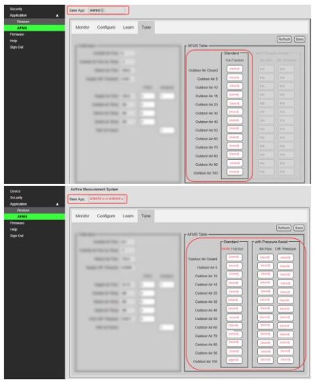
Access the AFMS Table and Record Data
Under Application > AFMS > Tune, in the AFMS Table group:
1. Locate the Characterized Airflow Performance™ data, found in:
• The OA Fraction column (for both standard and outside air damper pressure assist applications)
• The RA Fraction column (for return air damper pressure assist applications only)
• The SA Flow column (for both types of pressure assist applications only)
• The Diff. Pressure column (for both types of pressure assist applications only)
2. Record the data into the Note Sheets for AFMS Checkout and Commissioning:
• For standard applications, use the AFMS Post Table.
• For pressure assist applications, use the AFMS PA Post Table.
Set Control Mode
Under Application > AFMS > Configure, in the System Setup group:
1. For Control Mode, select from the drop-down menu the option that will be the AFMS’s normal mode for this installation:
• OA FLOW CTRL: The AFMS modulates the damper actuator to maintain the Outside Air Flow Setpoint (CFM).
• PASS THROUGH: The AFMS passes control of the damper actuator to another controller. (The AFMS measures and monitors only.)
• MAT CTRL: The AFMS modulates the damper actuator to maintain the Mixed Air Temp Setpoint (°F/°C).
2. Click Save.

ABOUT TESTING AND BALANCING AFMS
If everything was installed and configured correctly prior to running Learning Mode, the AFMS Table data is very reliable. The AFMS uses the same method from ASHRAE Standard 111 (Section 7.6.3.3, “Flow Rate Approximation by Temperature Ratio”) that a good tester and balancer should use. Furthermore, as the AFMS performs the method, it takes the OAT, RAT, and MAT measurements simultaneously and several times for reliable averages, increasing the reliability of the data.
However, should verification be required, the following guidelines should be observed:
• Make measurements using NIST-traceable instruments.
• Use the method from ASHRAE Standard 111, Section 7.6.3.3, “Flow Rate
Approximation by Temperature Ratio” to calculate the table data.
• Should an adjustment be needed, adjust single data items from the AFMS
Table rather than making a linear adjustment.
NOTE: TAB OA Factor (found in the Calibration group under Tune) should be at 1 and not adjusted.
If large adjustments need to be made to the AFMS Table data, one or more of the sensors may have been installed incorrectly and/or a setting was misconfigured prior to running Learning Mode. The problem should be corrected by fixing the installation and/or configuration, then running Learning Mode again.

DEVICE WINDOW
The Device window identifies the controller as a BACnet device and sets BACnet communication properties. The Device window also configures the controller for the Local Area Network (LAN). The new IP Address, Subnet Mask, and Default Gateway values are supplied by the building’s IT department system administrator.
NOTE: After changes in the window are saved, the controller will use the
new settings and will require you to log in at the new address. If the
controller is not on the same subnet as the network gateway router, it
will not function correctly.
The Device window shows multiple parameters (which vary depending on whether IP or Ethernet is selected):
- Device Name—The name must be unique among all devices on the BACnet internetwork.
- Description—Optional information not included in the device name.
- Location—An optional value that describes the controller’s physical location.
- Device Instance—A number that identifies the controller on the internetwork.
The device instance must be unique on the internetwork and in the range from 0–4,194,302. The device instance is assigned by the BACnet system designer. The default device instance is 1 and must be changed to a unique number to avoid conflict with other devices. - Number APDU Retries—Indicates the maximum number of retries that an APDU (Application Layer Data Unit) is retransmitted.
- APDU Timeout—Indicates the time (in milliseconds) between retransmissions of an APDU requiring an acknowledgment for which no acknowledgment has been received.
- APDU Seg. Timeout—The Segment Timeout property indicates the time (in milliseconds) between retransmissions of an APDU segment.
- Backup Failure Timeout—The time (in seconds) that the controller must wait before ending a backup or restore procedure. Use KMC Connect, TotalControl, or Converge to back up the controller.
- IP Address—The internal or private network address of the controller. (To recover a lost address, see Recovering an Unknown IP Address on page 19.
- MAC—The MAC address of the controller.
- Subnet Mask—The Subnet Mask determines which part of the IP address is used for a network identifier and which part is used for a device identifier. The mask must match the mask for the network gateway router and other devices on the subnet.
- Default Gateway—The address of the network gateway router. The controller and gateway router must be part of the same LAN subnet.
- UDP Port—UDP (User Datagram Protocol) is an alternative communications protocol to TCP used primarily for establishing low-latency and loss-tolerating “connectionless” connections between applications on the Internet.
The port is the “virtual channel” through which the data is transmitted and received. - Restart Device—Restarts the controller. This is similar to restarting the controller with a BACnet cold start from KMC Connect or TotalControl. A restart does not change properties or save changes not yet saved.

SECURITY WINDOW
The Security window sets user access to the controller:
- During configuration, the default admin/admin defaults should be changed to enhance security.
- The user name list must include at least one name with Administrator privileges.
- User names and passwords are case sensitive.
The controller has multiple levels of user access: - A View Only user may view configuration pages but not make any changes.
- An Operator may make configuration changes but cannot modify security settings.
- An Administrator may make configuration and security changes.
- A Custom access user has a combination of access options as selected by an Administrator.
The NetSensor Passwords section provides the viewing of and option to change the passwords required to access a controller using a Conquest STE-9000 series NetSensor or the KMC Connect Lite mobile app. These passwords are four digits, with each digit being a number 0 to 9. If all four numbers are 0, no password is required of the user for that level. For more information, see the Conquest Controllers Default Password Technical Bulletin after logging into the KMC Controls web site.

FIRMWARE UPDATE WINDOW
The AFMS controller’s firmware can be updated through the web browser after downloading the latest firmware from KMC Controls. To download from KMC Controls and install the firmware file onto the computer:
- Log into the KMC Controls web site and download the latest zipped firmware file from any AFMS controller’s product page.
- Find and extract the “Over-The-Network” (not the “HTO-1105_Kit”) EXE file for the relevant model controller (which must be a “BAC-xxxxCE-AFMS” version of the firmware).
- Run the BAC-xxxxCE-AFMS_x.x.x.x_OverTheNetwork.exe file.
- Click Yes to allow Windows to install the program.
- Click OK on the Firmware License dialog box.
- Click Unzip in the WinZip Self-Extractor dialog box.
To then load the firmware from the computer into the controller:
1. Log-in to the controller’s web page. See Login Window on page 3.
2. In the controller’s Firmware window, click Choose File, locate the new firmware zip file (it should be in a subfolder of C:\ProgramData\KMC Controls\ Firmware Upgrade Manager\BACnet Family), and click Open.
3. After being asked if you want to proceed with the download, click OK and the new firmware starts loading into the controller.
NOTE: To cancel the update and leave the devices with the original firmware intact, click the Cancel or Abort button.
4. After the new firmware is loaded, you will be asked if you want to commit to the download. To finish the update, click OK.
5. To put the firmware change into effect, the controller will need to be restarted. When asked if you want to restart the device, click OK.
6. After the controller restarts, you will need to log in again to continue any additional configuration. See Login Window on page 3.

HELP WINDOW
Go to KMC takes you to the KMC Controls public web site. Use the search to find the AFMS controller’s product page. Look at the various files that can be downloaded. You will need an active Internet connection for the link to work.
NOTE: Bulletins and firmware are available only after logging into the web site.
RECOVERING AN UNKNOWN IP ADDRESS
If the network address of the controller is lost or unknown, the controller will respond to the default IP address for approximately the first 20 seconds after power is applied.

To discover an unknown IP address:
- Disconnect the controller from the LAN and connect the controller as described in Login Window on page 3.
- On the computer, open a browser window and enter the default address of 192.168.1.251.
- Reconnect the controller to the power source and immediately attempt to connect with the browser. The browser will respond with the controller’s IP address and subnet mask.
- Once the address is known, connect the controller to the relevant IP subnet for normal operation or controller configuration.
NOTE: A controller’s IP address can also be seen in KMC Connect, TotalControl, and KMC Converge when the controller is properly connected to the network.
CHANGING YOUR COMPUTER’S ADDRESS
Introduction
To directly connect a computer to a controller, you must temporarily set the IP address of the computer to be compatible with the IP address of the controller. The IP address of a computer can be changed by using a utility or manually.
Change a Computer’s IP Address with a Utility
The easiest method for users who will change their IP address on multiple occasions is to install an IP address changing utility (such as Simple IP Config available from GitHub). See the instructions with the software.
In the software:
- Save a record/setting of your existing computer’s address information.
- Enter the following for the computer’s temporary new IP address, Subnet mask, and Gateway:
• IP address—192.168.1.x (where x is a number between 1 and 250)
• Subnet mask—255.255.255.0
• Gateway—Leave empty or unchanged (or if that does not work, use 192.168.1.***, where the last digits are different than the IP address in the computer or controller).
NOTE: After configuration of the controller is complete, revert your computer to the original IP settings.

Change a Computer’s IP Address Manually
Introduction
To change your computer’s IP address manually, follow the instructions (or the equivalent for your hardware and operating system) for Windows 10 (Settings) on page 21 or Windows 7 (Control Panel) on page 22.
NOTE: Screens will look different in different versions of Microsoft Windows.
NOTE: Depending on the computer and version of Windows, the exact name for the connection to the controller may be Ethernet, Local Area Connection, or something similar.


NOTE: If Obtain an IP address automatically is selected, the IP address and Subnet mask of the computer are not shown. They can be seen, however, by running ipconfig from a command prompt. To run ipconfig, type cmd in the Search box, at Command Prompt App press Enter, type in ipconfig at the prompt, and press Enter.
9. Record the existing settings of the Properties dialog.
10. Select Use the following IP address and then enter the following for the IP address, Subnet mask, and Gateway.
• IP address—192.168.1.x (where x is a number between 2 and 255)
• Subnet mask—255.255.255.0
• Gateway—Leave empty or unchanged (or if that does not work, use
192.168.1.***, where the last digits are different than the IP address in the computer or controller).
11. When all information is correct, click OK and OK.
NOTE: The changes should take full effect after a few seconds.
Windows 7 (Control Panel)
1. Click the Start button and select Control Panel.
2. From the Control Panel:
• (When viewed by icons) click Network and Sharing Center.
• (When viewed by category) click Network and Internet and then Network and Sharing Center.


3. Click the local connection for the LAN. Depending on the computer and version of Windows, the exact name for the connection may be Ethernet, Local Area Connection, or something similar.
4. In the Local Area Connection (or similar) Status dialog, click Properties.
5. Then click on Internet Protocol Version 4 (TCP/IPv4) and then click Properties.
NOTE: If Obtain an IP address automatically is selected, the IP address and subnet mask of the computer are not shown. They can be seen, however, by running ipconfig from a command prompt. To run ipconfig, click the Start button, type cmd in the Search box, press Enter, type in ipconfig at the prompt, and press Enter.
6. Record the existing settings of the Properties dialog.
7. In the Properties dialog, select Use the following IP address and then enter the following for the IP address, Subnet mask, and Gateway.
• IP address—192.168.1.x (where x is a number between 1 and 250)
• Subnet mask—255.255.255.0
• Gateway—Leave empty or unchanged (or if that does not work, use 192.168.1.***, where the last digits are different than the IP address in the computer or controller)
8. When all information is correct, click OK and Close.
NOTE: The changes should take full effect after a few seconds.
NOTE: After configuration of the controller is complete, repeat this process using the original IP settings.
TROUBLESHOOTING
- Check that the Ethernet connection cable is plugged into the Ethernet port and not the Room Sensor port.
- Check the network and connections.
- Restart the controller. See the Resetting Controllers section in the KMC Conquest Controller Application Guide.
- Review IP address and login information. See Introduction on page 3, Login Window on page 3, and Changing Your Computer’s Address on page 20.
- See Communication Issues—Ethernet section in the KMC Conquest Controller Application Guide.
HANDLING PRECAUTIONS
For digital and electronic sensors, thermostats, and controllers, take reasonable precautions to prevent electrostatic discharges to the devices when installing, servicing, or operating them. Discharge accumulated static electricity by touching one’s hand to a securely grounded object before working with each device.

IMPORTANT NOTICES
KMC Controls® and NetSensor® are all registered trademarks of KMC Controls. KMC Conquest™, KMC Connect™, KMC Converge™, and TotalControl™ are all trademarks of KMC Controls. All other products or name brands mentioned are trademarks of their respective companies or organizations.
The material in this document is for information purposes only. The contents and the product it describes are subject to change without notice.
KMC Controls, Inc. makes no representations or warranties with respect to this document. In no event shall KMC Controls, Inc. be liable for any damages, direct or incidental, arising out of or related to the use of this document.
The KMC logo is a registered trademark of KMC Controls, Inc. All rights reserved.
The KMC Connect Lite™ app for NFC configuration is protected under United
States Patent Number 10,006,654.
Pat. https://www.kmccontrols.com/patents/
SUPPORT
Additional resources for installation, configuration, application, operation, programming, upgrading and much more are available on the KMC Controls web site (www.kmccontrols.com). Viewing all available files requires logging in to the site.

© 2024 KMC Controls, Inc.
Specifications and design subject to change without notice
Read More About This Manual & Download PDF:
Documents / Resources
 |
KMC CONTROLS 5901 AFMS Ethernet [pdf] User Guide 5901, 5901 AFMS Ethernet, AFMS Ethernet, Ethernet |


