IOTELLIGENT ZK8201 RFID Read or Write Modul
Product Information
The ZK8201V1.0 ZK8201 RFID Read/Write Module is a device that allows for reading and writing data using RFID technology. It operates on the EPC C1G2 ISO18000-6C GB/T29768-2013 air interface protocol. The module has one SMA antenna interface (female) and an output power range of 0 to 30dBm with an accuracy of +/-1dB. It operates at a frequency band of 902 to 928 MHz for FCC and 840 to 845 MHz for China. The module is equipped with a 3.3V TTL UART communication interface and has a compact size of 62mm * 40mm * 12mm. It requires a DC power supply of 5V and has a power-saving mode to reduce power consumption. The module also provides ESD protection and is designed to be shock-proof. It can operate within a temperature range of -20°C to +60°C.
Product Usage Instructions
- Ensure that the module is stably fixed to the structure of the main machine and properly grounded.
- Before turning on the power, check if the antenna port is connected to the load.
- Ensure that the antenna standing wave is better than 2.0.
- Maintain a distance of at least 50cm between the user and the product when in use.
- For FCC compliance, follow the FCC standards: FCC CFR Title 47 Part 15 Subpart C Section 15.249.
- For installation, meet the IEC requirements for shock-proofing.
- In case of harmful interference with radio or television reception, try the following measures:
- Reorient or relocate the receiving antenna.
- Increase the separation between the equipment and the receiver.
ZK8201 RFID Read/Write Module Specification
The ZK8201 module is a single-channel UHF RFID module, developed by Iotelligent based on its own iBAT2000 chip. The module is specially designed to meet the needs of high-end RFID desktop label printers. The ZK8201 module provides one SMA antenna interface and 30dBm RF power output. While maintaining high-cost efficiency, this module achieves high integration, low power consumption, excellent performance, stability, and reliability, and has excellent anti-hamming ability. It is the preferred choice for high-performance/cost-effective UHF RFID desktop equipment.
Operation instructions
The module must be stably fixed to the structure of the main machine and ensure good grounding;
- Before turning on the power, please carefully check whether the antenna port has been connected to the load;
- Antenna standing wave is recommended to be better than 2.0.
Key technical parameters
Module specification
| Air interface protocol | EPC C1G2、ISO18000-6C、GB/T29768-2013 |
| Antenna interface | One SMA antenna interface (female) |
| Output power | 0 ~ 30dBm, accuracy +/-1dB |
|
Operating frequency |
FCC Band: 902 ~ 928 MHz
China Band II: 840 ~ 845 MHz |
| Connector | 8-pin connector |
| Communication interface | 3.3V TTL UART (115200 bps) |
| Dimensions | 62mm * 40mm * 12mm |
| DC power supply | DC voltage 5V |
| Power saving mode | Sleep mode 0.7W |
| Power consumption | 570mA@20dBm |
| ESD protection | 1500V |
| Shock-proof | Installation meets IEC requirements |
| Working temperature | -20℃ ~ +60℃ |
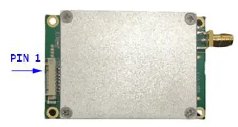
Module interface definition
| Interface pin | Definition | Functional description |
| 1 | SWDIO | SWD Data |
| 2 | SWCLK | SWD Clock |
| 3 | UART0_RX | Serial port 0 input |
| 4 | UART0_TX | Serial port 0 output |
| 5 | UART1_RX | Serial port 1 input |
| 6 | UART1_TX | Serial port 1 output |
| 7 | VCC | Power supply, +5V |
| 8 | GND | Grounding |
IC STATEMENT
This device contains license-exempt transmitter(s)/receiver(s) that comply with Innovation, Science and Economic Development Canada’s license-exempt RSS(s). Operation is subject to the
following two conditions:
(1) This device may not cause interference.
(2) This device must accept any interference, including interference that may cause undesired operation of the device The distance between the user and the products should be no less than 50cm
FCC Statement
FCC standards: FCC CFR Title 47 Part 15 Subpart C Section 15.249
Integral antenna with antenna gain -24.67dBi
This device complies with part 15 of the FCC Rules. Operation is subject to the following two conditions: (1) This device may not cause harmful interference, and (2) this device must accept any interference received, including interference that may cause undesired operation. Any Changes or modifications not expressly approved by the party responsible for compliance could void the user’s authority to operate the equipment.
Note: This equipment has been tested and found to comply with the limits for a Class B digital device, pursuant to part 15 of the FCC Rules. These limits are designed to provide reasonable protection against harmful interference in a residential installation. This equipment generates, uses, and can radiate radio frequency energy and, if not installed and used in accordance with he instructions, may cause harmful interference to radio communications. However, there is no guarantee that interference will not occur in a particular installation. If this equipment does cause harmful interference to radio or television reception, which can be determined by turning the equipment off and on, the user is encouraged to try to correct the interference by one or more of the following measures:
- Reorient or relocate the receiving antenna.
- Increase the separation between the equipment and the receiver.
- Connect the equipment to an outlet on a circuit different from that to which the receiver is connected.
- Consult the dealer or an experienced radio/TV technician for help.
FCC Radiation Exposure Statement
This modular complies with FCC RF radiation exposure limits set forth for an uncontrolled environment. This transmitter must not be co-located or operating in conjunction with any other antenna or transmitter. If the FCC identification number is not visible when the module is installed inside another device, then the outside of the device into which the module is installed must also display a label referring to the enclosed module. This exterior label can use wording such as the following: “Contains Transmitter Module FCC ID: 2BCD8-ZK8201 Or Contains
FCC ID: 2BCD8-ZK8201”
When the module is installed inside another device, the user manual of the host must contain below warning statements;
- This device complies with Part 15 of the FCC Rules. Operation is subject to the following two conditions:
- This device may not cause harmful interference.
- This device must accept any interference received, including interference that may cause undesired operation.
Note: This equipment has been tested and found to comply with the limits for a Class B digital device, pursuant to part 15 of the FCC Rules. These limits are designed to provide reasonable protection against harmful interference in a residential installation. This equipment generates, uses, and can radiate radio frequency energy and, if not installed and used in accordance with the instructions, may cause harmful interference to radio communications. However, there is no guarantee that interference will not occur in a particular installation. If this equipment does cause harmful interference to radio or television reception, which can be determined by turning the equipment off and on, the user is encouraged to try to correct the interference by one or more of the following measures:
- Reorient or relocate the receiving antenna.
- Increase the separation between the equipment and the receiver.
- Connect the equipment to an outlet on a circuit different from that to which the receiver is connected.
- Consult the dealer or an experienced radio/TV technician for help.
Changes or modifications not expressly approved by the party responsible for compliance could void the user’s authority to operate the equipment. The devices must be installed and used in strict accordance with the manufacturer’s instructions as described in the user documentation that comes with the product. Any company of the host device that installs this modular with limited modular approval should perform the test of radiated & conducted emission and spurious emission, etc. according to FCC part 15C: 15.247 and 15.209 & 15.207,15B Class B requirement, Only if the test result complies with FCC part 15C: 15.247 and 15.209 & 15.207,15B Class B requirement, then the host can be sold legally.
Basic information
POSTEK Technology Development Co., Ltd.
Address: Floor 18, Block 2, Building B, Wisdom Plaza,
No. 4068, Qiao Xiang Road, Nanshan District, Shenzhen, China
Test Principle

Test equipment
| Name | Model | Device ID |
Manufa ctures |
Calibrat ion Date | Next Cal date |
|
Network |
E5071B |
RFI-LAB- | Agilen | 2019.10.2 | 2020.10.22 |
| Analyzer | 012 | t | 3 | ||
|
Network |
E5071C |
RFI-LAB- | Agilen | 2019.10.2 | 2020.10.22 |
| Analyzer | 032 | t | 3 | ||
|
16 probes |
3*3*2.5 | RFI-LAB- 010 | Sunyie ld | 2019.03.1
5 |
2021.03.14 |
| microwave | |||||
| chamber |
Test environment
| Ambient
temperat ure |
23.2℃ |
| Relative humidity | 61%RH |
| Atmospher presure | 101.10k
Pa |
Sample information
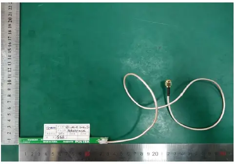
| Product name | UHF PCB Antenna |
| Sample model | POSTEK_A1 |
| Standard size | Antenna size:10.5mm*130mm;Line length:625mm |
| Factory serial
number |
/ |
| Test items |
VSWR; radiation pattern; antenna gain; efficiency; pattern circularity |
| Frequency range | 800-960MHz |
| Received date | 12/31/2019 |
| Test date | 01/02/2020 |
| Remark | / |
Sample physical picture
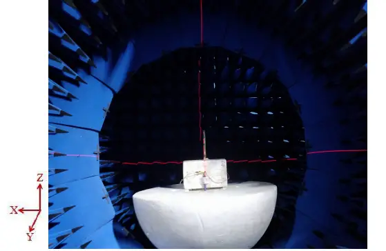
Placement of actual samples
Test results
Test basis
| Object name | Paramet er name | Method name | Standard number |
|
Mobile communicati on antenna |
VSWR |
General Technical Specifications for Mobile Communication Antennas |
GB/T 9410-2008 |
| Radiatio n pattern | |||
| Antenna gain | |||
| Efficien cy | |||
| Pattern circularity | |||
| Antenna |
Efficien cy |
IEEE Antenna test standard
procedure |
ANSI/IEEE
Std 149-1979 |
Test uncertainty
The calculation of uncertainty is based on the “Guide to the Expression of Uncertainty in Measurement” (GUM) issued by ISO and the expanded uncertainty is represented by a coverage factor of K=2 and a 95% confidence level
| Project | Uncertainty |
| VSWR | ±0.3 |
| Gain | ±1dB |
| Efficiency | ±10% |
Test data
Antenna network analyzer test

S11 Parameter data
| Frequency/MHz |
800 |
850 |
900 |
960 |
| VSWR | 1.07
74 |
1.08
75 |
1.07
09 |
1.04
22 |
Antenna gain and efficiency
|
Frequency/ MHz |
800 |
81 0 |
820 |
830 |
84 0 |
850 |
860 |
87 0 |
880 |
890 |
90 0 |
910 |
920 |
930 |
940 |
950 |
960 |
|
Max gain/ |
– |
– |
– |
– |
– |
– |
– |
– |
– |
– |
– |
– |
– |
– |
– |
– |
– |
| dBi | 22.
57 |
22.
93 |
23.
41 |
23.
50 |
23.
77 |
23.
96 |
24.
18 |
24.
18 |
24.
42 |
24.
64 |
24.
67 |
24.
88 |
25.
02 |
24.
92 |
24.
80 |
24.
79 |
24.
68 |
|
Efficiency /% |
0.1 8 |
0. 16 |
0.1 4 |
0.1 3 |
0. 14 |
0.1 1 |
0.1 0 |
0. 10 |
0.0 9 |
0.0 9 |
0. 09 |
0.0 9 |
0.0 9 |
0.0 9 |
0.0 9 |
0.0 9 |
0.0 9 |
Pattern circularity
| Freq
/MHz |
8 0 |
81 0 |
82 0 |
83 0 |
84 0 |
85 0 |
86 0 |
87 0 |
88 0 |
89 0 |
90 0 |
91 0 |
92 0 |
93 0 |
94 0 |
95 0 |
9 6 |
| 0 | 0 | ||||||||||||||||
| Out of round |
1 2 . |
10. 43 |
09. 19 |
08. 86 |
08. 47 |
08. 92 |
10. 46 |
10. 76 |
10. 20 |
09. 30 |
11. 26 |
14. 40 |
14. 44 |
12. 56 |
10. 95 |
12. 56 |
18. 22 |
| ness/ | 1 | ||||||||||||||||
| dB | 7 |
Radiation pattern

(3) X-Y Plane (The following entent is blank)
Documents / Resources
 |
IOTELLIGENT ZK8201 RFID Read or Write Module [pdf] User Manual 2BCD8-ZK8201, 2BCD8ZK8201, zk8201, ZK8201, RFID Read or Write Module, ZK8201 RFID Read or Write Module, Read or Write Module, Write Module, Read Module, Module |