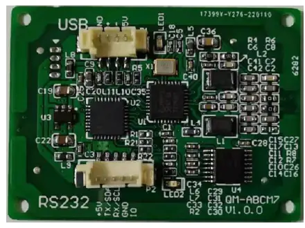
QUIO QM-ABCM7 IC Card Read/Write Module
Please read this manual carefully before using. If any problem, please mail to: kontakt@quio-rfid.de
Product introduction
QM ABCM7 is a modular circuit that reads and writes non contact IC cards by sending commands from users. The RF antenna and module of QM-ABCM7 adopt an integrated design. The impedance analyzer is used to adjust the RF circuit and the antenna to match the impedance, which can achieve very good read and write performance and very good stability. QM ABCM7 has many functions, supports a variety of international standards for contactless IC cards, and supports cards from many different suppliers. The designer has classified and integrated the commands of the non-contact IC card, so the commands issued by the user to the module are relatively simple, but it can complete the comprehensive operation of various non-contact IC cards. QM ABCM7 supports full-featured NFC, including card mode and peer-to-peer mode. Active mode and passive mode in peer-to-peer mode are also supported.
Technical parameters
- PCD type: PN512
- Working frequency 13.56MHz
- Supported standard: ISO14443A ISO14443B ISO18092
- Card supported: Refer to : module function configuration table
- Anti collision ability Full function anti collision; be able to set multi cards or single card
- Auto detecting card Supported, default OFF , could be set
- Power supply DC 5V ((±0.5V
- Interface CCID or RS232C USB HID book, when ordering
- Communication speed: RS232C 19200bps /9600bps/38400bps/57600bps/115200bps USB USB 2.0 HID or CCID
- Max. command length JCP04 25 3 bytes JCP05 510 bytes
- Power consumption 1 0 0mA
- Operating distance : 0 5 0mm depending on card quality
- Dimension 43.5 W *32 L 8 H mm
- Weight About 10 g
- ISP Compliant
- Operating temperature 25 +85
- Storage temperature 4 0 ~ +125
- RoHS Compliant
Physical parameter
Photo
Dimension
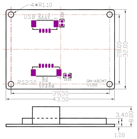
Pin configurations and pin outs
P1(USB)
| PIN | Function | Type | Description |
| 1 | VCC | Power | VCC(DC5V) |
| 2 | D- | Input / Output | USB D- |
| 3 | D+ | Input / Output | USB D+ |
| 4 | GND | Power | GND |
P2(RS232)
| PIN | Function | Type | Description |
| 1 | VCC | Power | VCC(DC5V) |
| 2 | TXD | Output | RS232C TXD |
| 3 | RXD | Input | RS232C RXD |
| 4 | GND | Power | GND |
| 5 | IO | Output | External I/O |
Module function configuration table
| QM-ABCM7P | QM-ABCM7 | |
| PCD | PN512 | PN512 |
| PC/SC | ● | |
| JCP04 | ● | |
| JCP05 | ● | |
| MIFARE 1K | ● | ● |
| MIFARE 4K | ● | ● |
| MIFARE Ultra Light | ● | ● |
| MIFARE Ultra Light C | ● | ● |
| MIFARE Mini | ● | ● |
| DESfire | ● | ● |
| MIFARE Plus | ● | ● |
| T=CL TYPE A | ● | ● |
| SR176 | ● | |
| SRI512 | ● | |
| SRI1K | ● | |
| SRI2K | ● | |
| SRI4K | ● | |
| SRIX4K | ● | |
| T=CL TYPE B | ● | |
| Data Flash | 512 bytes | |
| Interface | CCID | HID+RS232C |
Communication Protocol
The physical interfaces of module are various. But the data link layer protocols are in accordance with JCP04 & JCP05. Please reference “ QM ABCM7 Series IC Card Mod ule General Technical Manual V6.21 ”. For convenience to test the module, we supply PC software: Trans p ort to users. We have interface program source code to help users also. They are KELL projects in C51 or ASM51 format.
Copyright © 2003-2022 Quick Ohm Küpper & Co. GmbH. A ll rights reserved
Documents / Resources
 | QUIO QM-ABCM7 IC Card Read/Write Module [pdf] User Manual QM-ABCM7 IC Card Read Write Module, QM-ABCM7, IC Card Read Write Module, IC Card Module, Read Write Module, Module |