invt ICA400-02 4G IoT Data Transmission Terminal
Product overview
INVT ICA400-02/ICA413-02 4G series IoT data transmission terminal is a kind of 4G wireless data terminal for Internet of Things (IoT). Aiming at the need for RS485 or Ethernet communication, the data transmission terminal collects the device data of the RS485 interface through the ModbusTCP protocol or the device data of the RJ45 interface through the ModbusTCP protocol and provides users with wireless long-distance data transmission function through the public operator network. Its stability and reliability meet the requirements of industrial application scenarios.
The product adopts a high-performance industrial-grade 32-bit communication processor and industrial-grade wireless module, with an embedded real-time operating system as the software support platform, and also provides RS485/ RJ45 Ethernet interfaces, thus enabling PLC and other devices to upload the data to the cloud.
Product features
Standard set-up for easy operation
- Provides standard RS485 interfaces for direct connection to serial devices for data acquisition.
- Provides standard RJ45 interfaces for direct connection to network devices for data acquisition (ICA413-02 model).
- With intelligent data terminal, able to enter the data transmission state once upon power-on.
- Adopts standard rail installation.
- With powerful center management software, facilitating device management (optional).
- Convenient system configuration and maintenance interface.
Powerful functions
- Supports remote wireless software upgrade and remote policy configuration through OTA.
- Supports cloud-platform management on devices, facilitating remote management and device intelligence.
- Embedded with standard TCP/IP protocol stacks, supporting multiple transmission protocols.
- Supports APN.
- Able to directly connect to serial devices, supporting up to 40 groups of Modbus register collection for terminal devices.
- Supports the configuration of Modbus query address and collection period to upload only changed data, achieving the traffic saving on data upload.
- Supports 4G base station positioning.
- Supports SIM cards (optional).
- Supports GPS positioning to obtain device positions accurately (optional).
Product specifications
| Function | Description |
| Supported network | China(CN) version
|
| Supported interfaces |
|
| Indicator | Power indicator, network status indicator, running status indicator |
|
Communication protocol |
Modbus RTU/Modbus TCP protocol IoT MQTT communication protocol PPP dialing protocol
FTP transfer protocol |
| Theoretical bandwidth |
|
| Antenna gain | 2.2dBi |
| Power supply | DC10–25V |
| Power consumption | ICA400-02 series: Average power: 40mA@24V, maximum power: 500mA@24V.
ICA413-02 series: Average power: 50mA@24V, maximum power: |
| Function | Description |
| 500mA@24V. | |
| Temperature
range |
-25–+60ºC |
| Shell | With shell, ingress protection (IP) rating IP20 |
| Installation method | Rail-mounted |
| Heat dissipation
method |
Natural heat dissipation |
Model instruction
Model name illustration of INVT ICA series data transmission terminal:
| Symbol | Description | Contents |
| ① | Product series abbreviation | ICA: Internet Communication Adapter |
| ② | Wireless communication mode |
|
| ③ | Wire communication mode |
0: Do not support wire communication 1: Ethernet |
| ④ | Local data collection mode | 0: RS485
|
| Symbol | Description | Contents |
| ⑤ | SIM card type | 0: Plug-in card (Standard, default) 1: Embedded SIM card |
| ⑥ | IP rating | 0: IP00 (without shell)1: IP20 (wall-mounted shell) 2: IP20 (rail-mounted shell) 6: IP65 (direct-insert shell) |
| ⑦ | Special function | G: with GPSU: with USB flash disk A: supports audioV: supports videoThis bit is omitted for standard configuration since it does not carry additional functions. |
| ⑧ | Voltage type | 5: 4.5–6V.The voltage for standard configuration is 10V–30V, so this bit is omitted for standard configuration. |
| ⑨ | International version | CN: China version EU: Europe version LA: Americas versionThis bit is omitted for WIFI products. |
Port instruction
| Port identifier | Port description |
| 24V | Power supply + |
| GND | Power supply – |
| 485+ | 485A |
| 485- | 485B |
| 4G | GPRS antenna |
| GPS | GPS antenna (optional) |
| Ethernet | RJ45 interface (applicable to ICA413-02 only) |
| SIM | SIM card |
| WAN←→LAN | Function selection switch. The selection before power-up is valid.
|
Indicator instruction
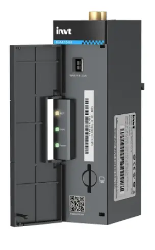
| Indicator identifier | Description |
| NET | 4G network indicator
Flash slowly (ON: 600ms; OFF: 600ms): No SIM card/Network registration in progress/Registration failed. Flash quickly (ON: 75ms; OFF: 75ms): Data link established |
| RUN | Run indicator
Flash slowly (ON: 1s; OFF: 1s): RS485 communication is abnormal Flash quickly (ON: 100ms; OFF: 100ms): RS485 communication is normal ON or OFF: System exceptions |
| POWER | Power supply indicator |
Installation
Overview
ICA series 4G IoT data transmission terminal must be installed properly to achieve the designed function. Generally, the installation must be done under the guidance of our certified and qualified engineers.
Note: Do not conduct installation with the power on.
Unpacking inspection
Before unpacking, check whether the package is in good condition and its product information is the same as on the order. The packing materials should be well maintained during inspection for future transshipment. If any question, please contact the supplier.
Table 2-1 Product deliverables
| Deliverables | Qty | Remark |
| 4G data transmission terminal | 1 | |
| 4G antenna | 1 | Applicable only to models using an external
antenna |
| GPS antenna | 1 | Optional |
| SIM card | 1 | Applicable to models of China(CN) version |
| PIN terminal | 1 | 4PIN terminal |
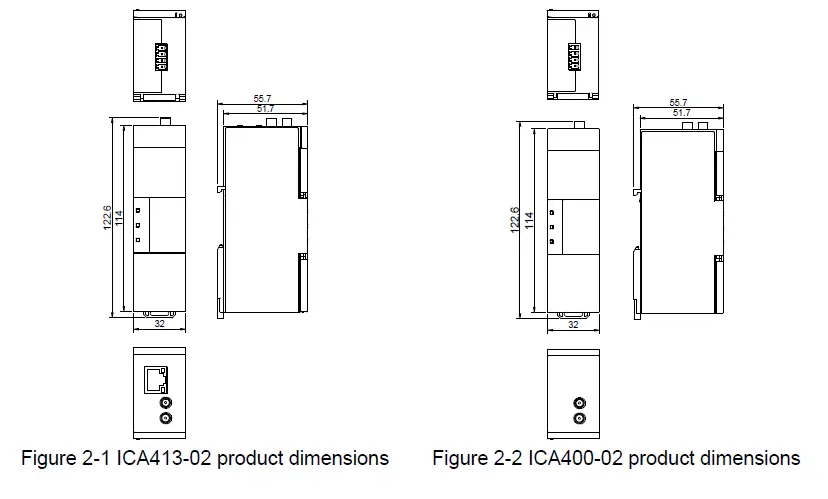
Outline dimensions and weight
The outline dimension of the IP20 model is as follows (unit: mm)
The net weight of the ICA413 product is 97.1g, and the gross weight is 264g. The net weight of the ICA400 product is 90.7g, and the gross weight is 258.7g.
Quick startup
Operation description
Equipment required: Networked computer, 4G data transmission terminal, IoT SIM card. Procedure:
- Step 1 Open the flip cover at the front and insert the SIM card into the slot.
- Step 2 Record the device ID and 6-digit key from the label and add them to the IoT monitoring system.
- Step 3 Wire the product based on the port description (ICA413 models have the option to connect to a network cable).
- Step 4 Connect to the 4G antenna and GPS antenna (optional).
- Step 5 Power on and start the 4G data transmission terminal.
- Step 6 If the yellow NET indicator flashes with an interval of 75ms, the expansion card is network ready and the data transmission starts.
- Step 7 Go to real-time monitoring interface to review relevant information in IoT monitoring system.
Monitoring platform operation instructions
You can monitor relevant devices through the following three methods. For information on how to obtain the account and password, please refer to section 3.3 Monitoring platform account.
- Host controller software: IWOstudio
- Web: IWoscene industrial IoT application platform
- Mobile: INVT Cloud APP
IWOstudio monitoring equipment
- Download IWOstudio from the official website (www.invt.com), install, and then open it.
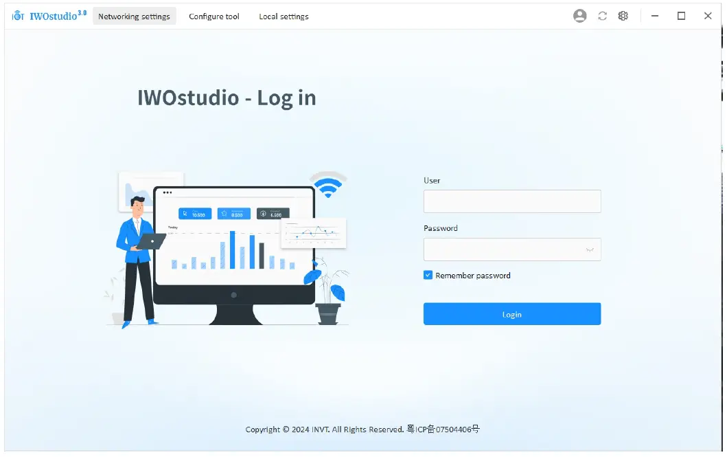
- Enter the account and password to log in and enter the network configuration interface.
Note: For account information, refer to section 3.3 Monitoring platform account.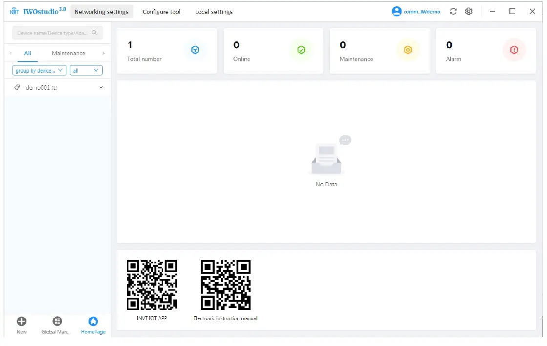
- If it is your first time using the software, you need to add a device type. Click New > New device type in the lower left corner. If it is not your first time adding a device type, proceed to step 5.
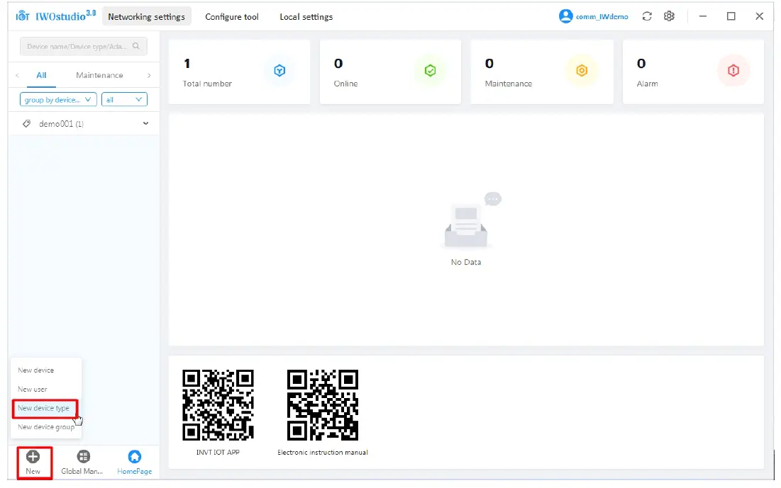
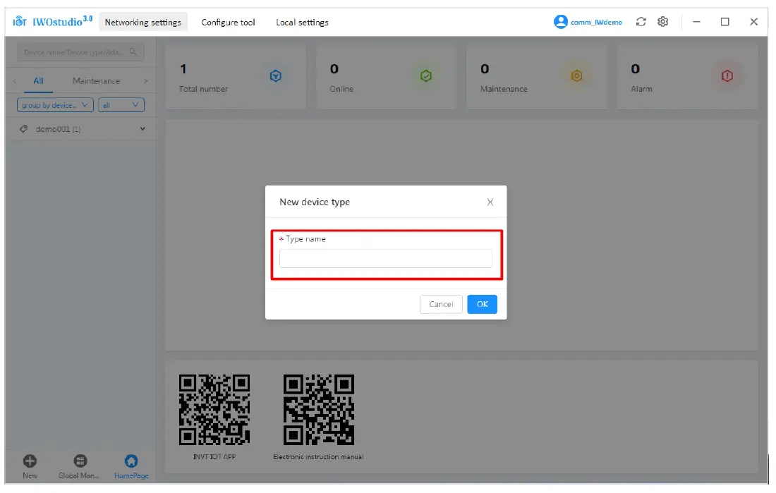
- Enter the type name of the input device, and click OK. When a prompt of Successfully created appears, the creation of the device type is complete.
- Click New > New device in the lower left corner.
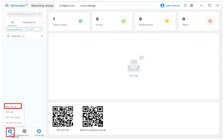
- Enter Adapter ID, Adapter key, Device name, select Device type, and click OK to complete the process.
Note: Adapter ID is the S/N code of the IoT terminal, and Adapter key is the six-digit number under the QR code next to the S/N code.
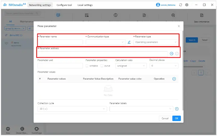
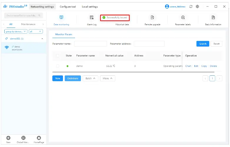
- After adding the device, you need to add parameters for the first time. Click the device and then click New.
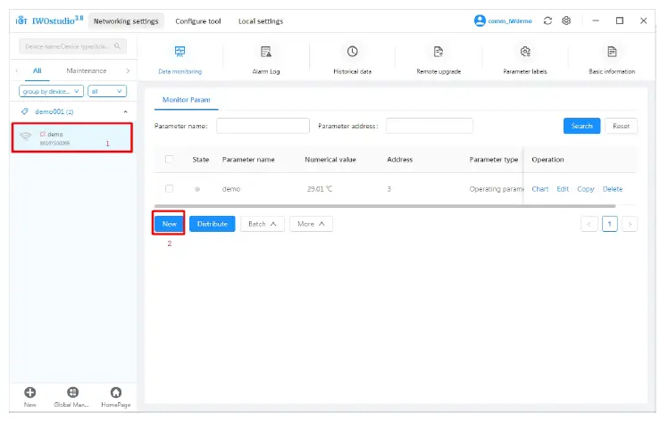
- Enter Parameter name, select Communication type, select Parameter type, enter Parameter address (Modbus address of the register), fill in other information as needed, and click OK. When the prompt Successfully created appears, the process is complete.
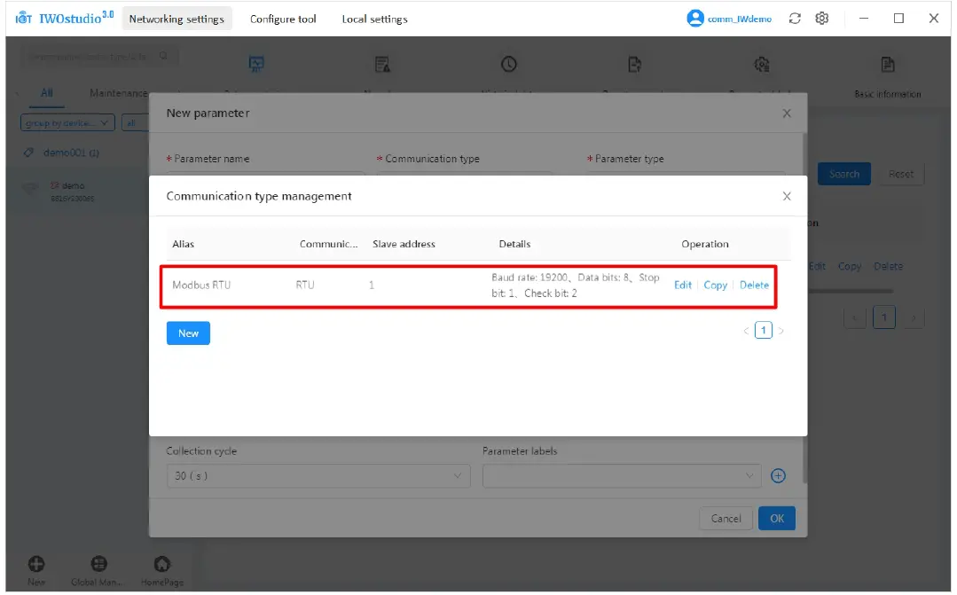
 Communication type: Click
  to view, modify or create new settings. The default is 485 communication, with a slave address of 1, a baud rate of 19200, 8 data bits, 1 stop bit, and even parity. Click Edit to modify. If additional communication parameters are required, you can perform create operations.
Note: This parameter determines whether the terminal can successfully communicate with the device. Ensure that it corresponds to the device before sending the parameters.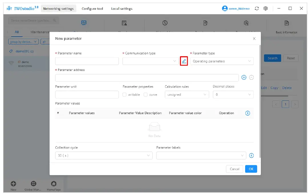
- After creating the parameters, click Distribute.
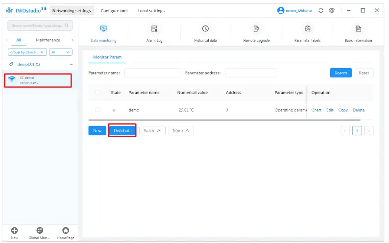
- Once successfully distributed, you can proceed with online monitoring.
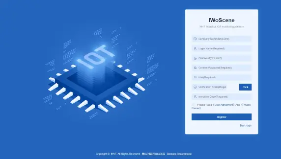
Web monitoring device
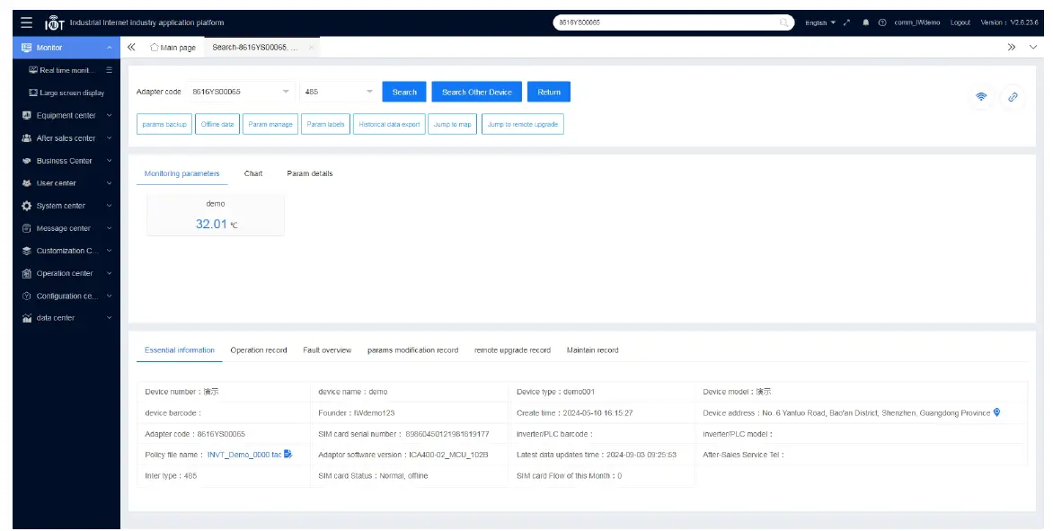
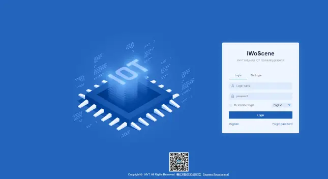
- Enter: iot.invt.com in the address bar of Google Browser and press Enter to visit the login page of the industrial IoT application platform. As shown in the following figure, enter the account number and password to complete the login.
Note: For account information, refer to section 3.3 Monitoring platform account.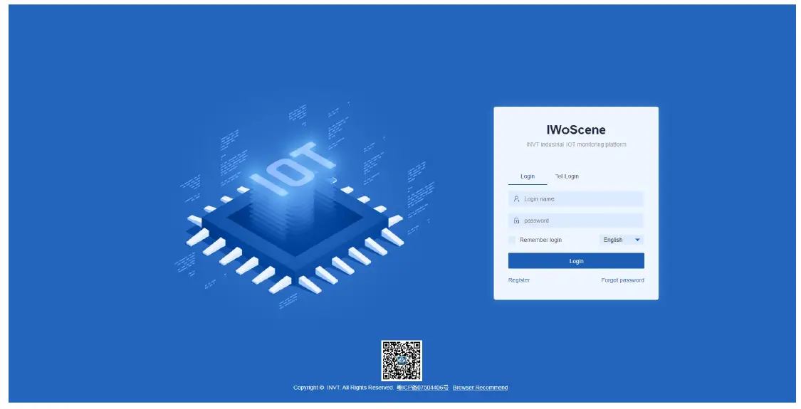
- After logging in successfully, the homepage appears as shown below. Enter the adapter number, secret key and device name in the Add devices quickly column on the homepage, select the device type according to the monitoring type, and select ICA400/413 as the adapter type (default communication is 485). Click Submit after confirming the input is correct. When a prompt of “Added successfully” appears, the device is added completely.
Note: The adapter code is the S/N code of the IoT terminal, and the adapter secret key is the six-digit number below the QR code next to the S/N code.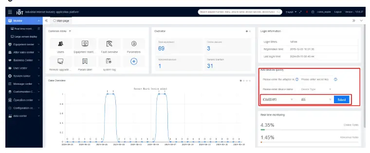
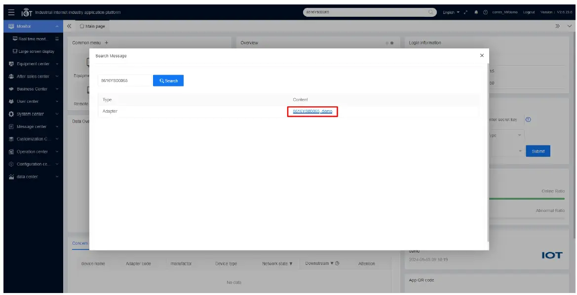
- Enter the adapter code that has been added into the search box on the homepage, click the barcode to enter the monitoring page of the device and check the monitoring state of the device.
Monitoring the device via APP
- Download and install the INVT Cloud APP on your mobile device.
Note: You can download it by searching for INVT in Tencent MyApp Store or Google Play (for iOS system, you can search for INVT in the APP Store). - Open the INVT Cloud APP, enter the account and password to log in. On the homepage, click the + icon in the upper-right corner, enter Adapter code, Secret key and Device name, select Device type, and click Submit to complete the device addition.
Note: For account information, refer to section 3.3 Monitoring platform account.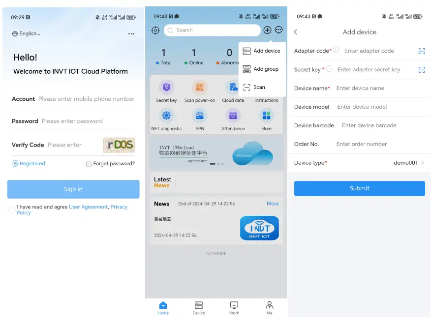
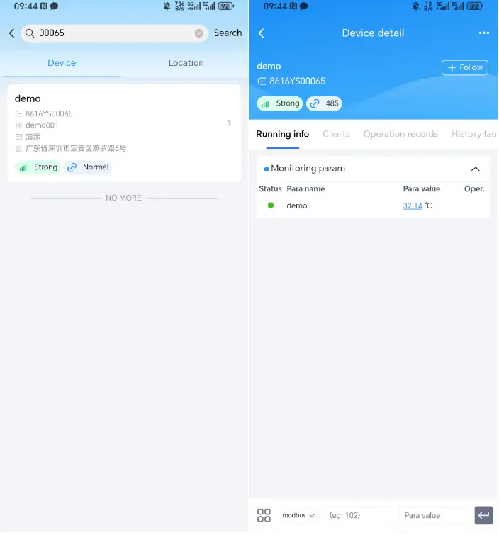
- In the search bar, enter the adapter code to search. Click the device to enter the monitoringpage and monitor the device.
Monitoring platform account
You can register a monitoring platform account through the Web or APP, and the same account and password can be used on all three monitoring platforms.
Web registration
- Step 1 Enter: iot.invt.com in the address bar of Google Browser and press Enter to visit the login page of the industrial IoT application platform.
- Step 2 Click Registered.
- Step 3 Fill in the Company name, User name, Password, then confirm the password again. Enter your Mobile number, click Verification code, fill in the verification code received via SMS, and enter the invitation code. Invitation code: You can obtain it through the higher-level user account. If there is no higher-level one, you can fill in dbf20a (INVT administrator invitation code). Review and check the User Privacy Agreement, click Register, and wait for review. You will receive a notification via SMS once approved.
APP registration
- Step 1 Download and install the INVT Cloud APP on your mobile device.
Note: You can download it by searching for INVT in Tencent MyApp Store or Google Play (for iOS system, you can search for INVT in the APP Store).
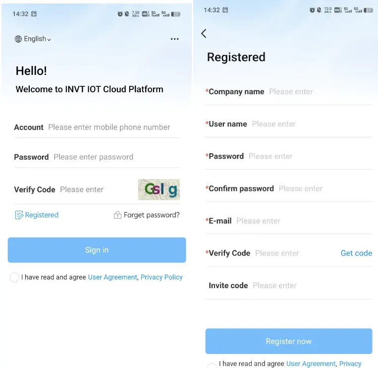
- Step 2 Open the INVT Cloud APP, and click Registered.
- Step 3 Fill in the Company name, User name, Password, then confirm the password again. Enter your Mobile number, click Verification code, fill in the verification code received via SMS, and enter the invitation code. Invitation code: You can obtain it through the higher-level user account. If there is no higher-level one, you can fill in dbf20a (INVT administrator invitation code), review and check the User Privacy Agreement, click Register, and wait for review. You will receive a notification via SMS once approved.
FAQs
- After powering on, the power indicator does not flash or light up. Answer: Check whether the power supply voltage polarity is reversed, and whether the input voltage 24V and GND are in consistent with the silkprint on the casing.
- After power on for three minutes, the network status indicator flashes quickly at a frequency of 75ms, and no data is displayed on the web page.
Answer:
- The expansion card with a SIM card is not installed properly. Power off and re-install it for ensuring good connection.
- Move the antenna of the IoT transmission terminal to a place with good signal.
- Ensure that the SIM card is activated and has remaining balance.
- Contact the manufacturer to check whether the device ID is registered.
- Data uploading doesn’t match the web page display.
Answer:
- Re-power on and upload all data again.
- Check whether the order and device type is matching, if not, please contact the manufacturer.
- The indicator flashes normally but the web system displays no data.
Answer: Check the communication cable between the Modbus terminal device and IoT transmission terminal is well connected. - In the web system, only data content can be displayed, and commands cannot be issued.
- Answer: Check whether the signal-enabling switch of the Modbus terminal device is turned on.
- The network status light stays off after the ICA413-02 model is powered on.
Answer: Check the WAN←→LAN switch. 4G network is only available when the switch is turned to LAN. - How to use the function selection switch on the ICA413-02 model.
Answer: The ICA413-02 model provides a function selection switch. When the switch is turned to WAN, the network port is used to connect a well-networked router with a network cable and the PLC and other devices are connected through the RS485 port. When the switch is turned to LAN, the IoT data transmission terminal connects to network through 4G network and connect PLC and other devices through RS485 or network cable. What happens if two devices are connected to the ICA413-02 model at the same time when the network port is downstream? - Answer: When there are devices connected to both RS485 and network ports, only data from the network port will be collected.
Service line: 86-755-23535967 E-mail: overseas@invt.com.cn Website: www.invt.com
- The products are owned by Shenzhen INVT Electric Co.,Ltd.
- Two companies are commissioned to manufacture: (For product code, refer to the 2nd/3rd place of S/N on the name plate.)
- INVT Power Electronics (Suzhou) Co.,Ltd. (origin code: 06)
- Shenzhen INVT Electric Co.,Ltd. (origin code: 01)
- Address: No. 1 Kunlun Mountain Road, Science & Technology
- Address: INVT Guangming Technology Building, Songbai Road,
- Town, Gaoxin District, Suzhou, Jiangsu, China
- Matian, Guangming District, Shenzhen, China
- Industrial Automation:
- Energy & Power:
- VFD
- Rail Transit Traction System
- Servo System
- Elevator Intelligent Control System
- DCIM
- Solar Inverter
- New Energy Vehicle Powertrain
- System New Energy Vehicle
- Charging System
- New Energy Vehicle Motor
Copyrighto INVT.
Manual information may be subject to change without prior notice.
Documents / Resources
 |
invt ICA400-02 4G IoT Data Transmission Terminal [pdf] Instruction Manual ICA400-02, ICA400-02 4G IoT Data Transmission Terminal, 4G IoT Data Transmission Terminal, Data Transmission Terminal, Terminal |
