 Wireless Door Control
Installation Guide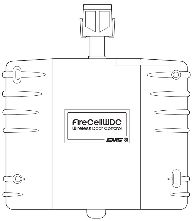
Part number and description
FC-60-2000: FireCell Wireless Door Control (Black)
FC-60-2010: FireCell Wireless Door Control (White)
Pre-installation
![]() Installation must conform to applicable local installation codes and should only be installed by a fully trained competent person.
Installation must conform to applicable local installation codes and should only be installed by a fully trained competent person.
- Ensure that the device is installed as per the site survey.
- Ensure that the device is fitted to the side of the door that shuts against the door frame.
- Check that the fire door is suitable e.g. self-closing, has a surface to fix to, and has appropriate clearance under the door to accommodate the floor plate.
- The supplied ESD protection label must be fitted when installing the Wireless Door Control (WDC) on metal kick plates or uneven surfaces.
- Any door closing devices used in conjunction with the WDC must conform to EN 1154.
- DO NOT press the log-on button on a pre-programmed device, as this will cause communication with the control panel to be lost. Should this happen, delete the device from the system and add it back on.
Components
- FireCell WDC
- Small & large floor plates
- Fixing template (MK255)
- Fixings
- ESD protection label

Equipment familiarisation

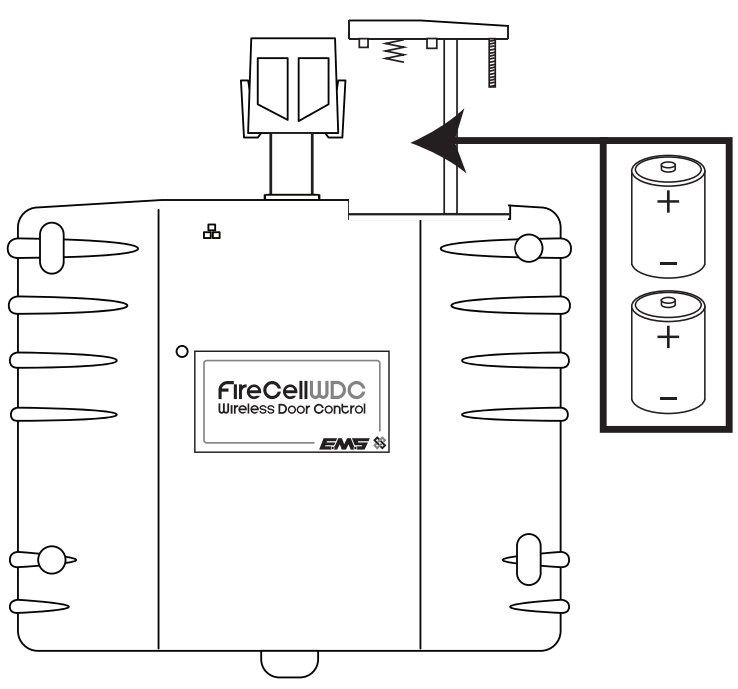
Insert batteries
- When fitting / replacing batteries; observe correct polarity, using only specified batteries.
![]() Note; upon first power up the device will initiate a startup sequence, denoted by a series of low-pitched beeps and motor operations. This sequence will take approximately 15 seconds and concludes with three low-pitched beeps. Should the sequence close with a mix of high and low-pitched beeps, refer to page 13.
Note; upon first power up the device will initiate a startup sequence, denoted by a series of low-pitched beeps and motor operations. This sequence will take approximately 15 seconds and concludes with three low-pitched beeps. Should the sequence close with a mix of high and low-pitched beeps, refer to page 13.
Add to the system – unprogrammed systems only
![]() Skip this step If the device has been supplied as part of a pre-programmed system, as this will cause communication with the control panel to be lost. Should this happen, delete the device from the system and add it back on.
Skip this step If the device has been supplied as part of a pre-programmed system, as this will cause communication with the control panel to be lost. Should this happen, delete the device from the system and add it back on.
The device’s loop address is configured within the menu structure of the radio hub. It is recommended to configure the device to the system prior to installation.
Note; devices can alternatively be added to the system after installation. If this method is to be taken, it is recommended to note the device’s ident number at this stage. Skip this section and refer to the ‘Post Installation Configuration section on page 10 for details on the device’s ident location.
Note; if programming the FireCell WDC to a Fusion Loop Module, refer to the Fusion Loop Module Engineers Guide (TSD062) for programming details.
To add devices by logging on (pre-installation);
From Front Display ![]() Add New Device Select Desired RCC 01
Add New Device Select Desired RCC 01 ![]() Set Loop 1 .
Set Loop 1 . ![]() Addr 003
Addr 003 ![]() Add By Log On
Add By Log On ![]() Press Dev Log On ‘press the devices log on the button, followed by Add Dev 03456 Y?
Press Dev Log On ‘press the devices log on the button, followed by Add Dev 03456 Y? ![]() New Addr L1 A003.
New Addr L1 A003.
![]() To Exit
To Exit
The device has now been added to the Radio Hub and should be installed in its location. For further details, refer to the programming manual (MK98) for full programming information.

Free to download from www.emsgroup.co.uk
Note: the device can also be programmed utilizing the control panel’s cause and effects, as part of the building’s evacuation plan.
Assign device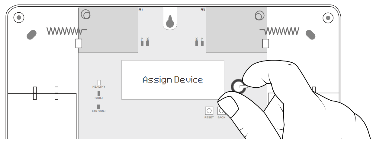
Newly added devices must now be assigned to the system.
From Unassigned Dev ![]() Assign Device
Assign Device ![]() Assign All
Assign All ![]() Dev 000 of 001 changing to Done 001 of 001 (once complete)
Dev 000 of 001 changing to Done 001 of 001 (once complete)
![]() To Exit
To Exit
![]() Note: the device must now also be added and configured on the control panel. Refer to the FireCell Programming Guide (MK98) for details.
Note: the device must now also be added and configured on the control panel. Refer to the FireCell Programming Guide (MK98) for details.
Position template against the door

![]() If the device is to be fitted to a metal surface, e.g. a metal kick plate, the ESD protection label must be fitted. Simply affix the label inside the fixing template cut out, onto the metal surface.
If the device is to be fitted to a metal surface, e.g. a metal kick plate, the ESD protection label must be fitted. Simply affix the label inside the fixing template cut out, onto the metal surface.
Drill fixing positions
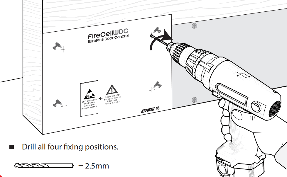
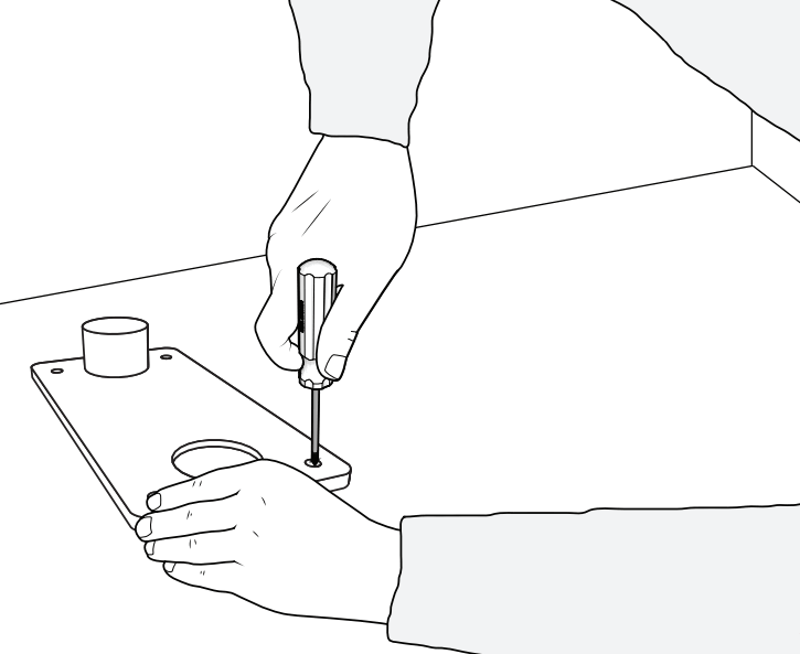
Fix unit to the door
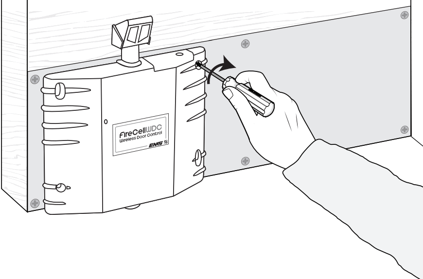
- Use all four fixing positions.
- Use supplied fixing screws.
Position floor plate
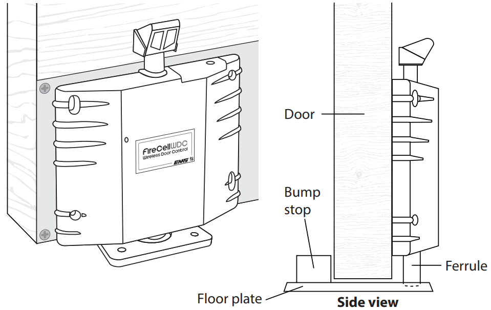
Mark floor plate fixing positions
- Mark all four fixing positions.
![]() Use a small floor plate, if a bump stop creates a trip hazard
Use a small floor plate, if a bump stop creates a trip hazard

Drill floor plate fixing positions
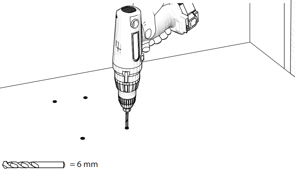
![]() Before drilling, check the locations of water pipes, gas pipes & electrical cables
Before drilling, check the locations of water pipes, gas pipes & electrical cables
Fix floor plate to the floor
- Use all four fixing holes.
- Use supplied fixing screws.
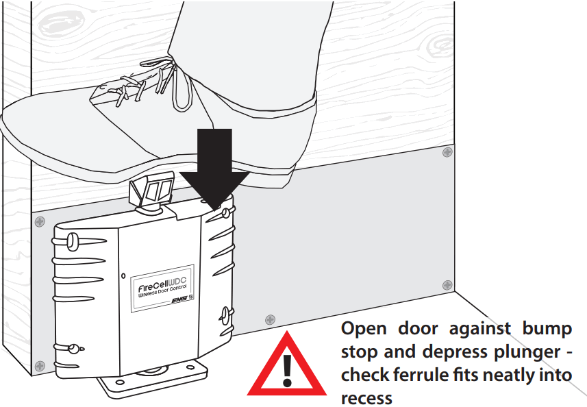
Open the fire door & depress the plunger
Post-installation configuration
![]() Skip this step if the device has already been configured to the system
Skip this step if the device has already been configured to the system
Ensure the device’s ident number has been noted. The device’s ident is located at the top of the device as shown:
To add devices by ident (post-installation);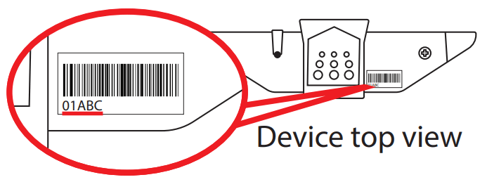
From Front Display ![]() Add New Device Select Desired RCC 01
Add New Device Select Desired RCC 01 ![]() Set Loop 1
Set Loop 1![]() . Addr 003
. Addr 003 ![]() Add By Ident
Add By Ident ![]() Add Dev 01ABC Y? ’Enter the Device’s ident. ’Enter the device type
Add Dev 01ABC Y? ’Enter the Device’s ident. ’Enter the device type ![]() Input Output Device
Input Output Device ![]() New Addr L1 A003
New Addr L1 A003 ![]() .
.
![]() To Exit
To Exit
The device must now be assigned to the system. Refer to the ‘ Assign Devices’ section on page 6 for details.
Test device
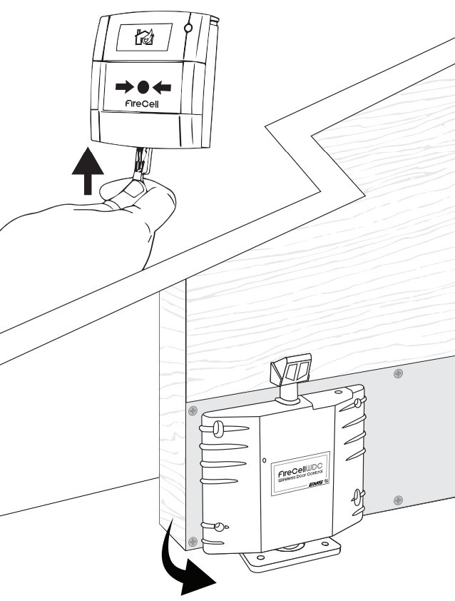
Troubleshooting
In the rare event of an issue with the device’s operation, refer to the points below:
Is the device not releasing upon a fire alarm condition?
- Check that the device is added correctly to the system and that it is fault free at the FireCell radio hub.
- Check that the door closes freely when closed manually.
- Check that the plunger has a minimum of 10 mm clearance between the ferrule and the floor/floor plate.
- Check that the WDC’s output properties are set correctly within the control panel programming.
Why does the fire door not close freely?
- Check that the ferrule is not worn or damaged. Replace as necessary.
- Check that the plunger has a minimum of 10 mm clearance between the ferrule and the floor/floor plate.
Device not holding the door in an open position
- Check that the plunger is depressed fully.
- Check that the device is added correctly to the system and fault free at the FireCell radio hub.
- Check that the device is positioned low enough for a good connection between the ferrule and the floor plate. The optimum plunger movement is 10 – 15 mm.
The device is tamper at fault?
- Check that the device is fixed correctly to the door.
- Check that the surface is flat and that the tamper switch is engaging correctly when the device is fixed to the door.
Battery fault/device not powered?
- Check the polarity and the voltage of the batteries.
- Check that the battery cover is fltted correctly.
- Do NOT Press the log-on button on a pre-programmed device, as this will cause communication with the control panel to be lost. Should this happen, delete the device from the system and add it back on.
Device tone and flash indication
In addition to fault reporting at the control panel, the FireCell WDC has various beep and flash sequences to indicate a number of conditions.
During device startup sequence/motor operation
| Beep sequence | Flash sequence | Indicative meaning | Action required |
| Low-Low-Low | None | Start-up complete | None |
| High-High-Low (repeated until resolved) |
Red-Red (on the first two beeps only) | Motor fault* | Remove and re-insert batteries |
| High-High-HighHigh-Low- LowLow-Low | Red-Red-Red-Red (on the first four beeps only) | Internal fault (non-serviceable part) | Remove and re-insert batteries (If the fault persists, return to manufacturer) |
| None | Red-Green | Battery pack 1 low /incorrectly inserted (2x C batteries) |
Replace/remove and re-insert batteries (as appropriate) |
During standard operation
| Beep sequence | Flash sequence | Indicative meaning | Action required |
| Low-Low-High (repeated until the plunger releases) |
Red (on low beeps only) | Plunger fault | Check for obstructions to the plunger |
| High-Low-Low-Low (repeated until resolved) | Red (on first sequence only) | Internal fault (non-serviceable part) | Remove and re-insert batteries (If the fault persists, return to manufacturer) |
| High-Low (seven times, then door releases) |
Red (on the first beep in sequence only) | The door is about to close† | Move away from the doorway |
* Additional notification will be reported at the control panel as an analog value 4 fault – Tamper/ Input Fault (short or open circuit).
† Door closing can be a result of many factors such as a fire condition, a loss of communication, or a battery critical condition. Refer to the control panel for details.
Specification
| Operating temperature | -10 to +55 °C |
| Storage temperature | 5 to 30 °C |
| Humidity | Up to 95% non-condensing |
| Supply | 2x C alkaline (Panasonic LR14AD Powerline / Varta 4014 Industrial) |
CAUTION!
- This is a life safety product. Only use manufacturer-approved battery types.
Failure to do so may result in damage to the product. - DO NOT mix batteries of different types or ages.
- When replacing batteries; remove all old batteries before fitting replacements.
| Supply voltage | 2.22 to 3.3 VDC |
| Current consumption | 60 A |
| Operating frequency | 868 MHz |
| Output transmitter power | Auto-adjusting 0 to 14 dBm (0 to 25 mW) |
| Signaling protocol | X2 |
| Dimensions (W x H x D) | 195 x 205 x 45 mm |
| Weight | 0.5 kg |
| Location | Type A: For indoor use |
| Max. hold open power size | 7 |
| Max. door leaf width | 1600 mm |
| Max. test door mass | 160 kg |
| ax. overload test drop weight | 36 kg |
| Max. test door friction | 0.8 Nm |
| Min. angle between door open and closed positions | 66 ° |
Note: FireCell WDC is not for use on metal doors.
Regulatory information
| Manufacturer | Carrier Manufacturing Polska Sp. Z o.o. Ul. Kolejowa 24. 39-100 Ropczyce, Poland |
| Year of manufacture | See device serial number label |
| Certification | |
| Certification body | 905 |
| CPR | 0359-CPR-00648 |
| DoP | BS EN1155:1997. Incorporating Amendment No. 1 and Corrigendum Nos. 1, 2, and 3. BS 7273-4:2007. Code of practice for the operation of re-protection measures – Part 4: Actuation of release mechanisms for doors. (Category B) EN54-25:2008. Incorporating corrigenda September 2010 and March 2012. Fire detection and re-alarm systems. Part 25: Components using radio links. |
| Approved to | EMS declares that this device is in compliance with Directive 2014/53/EU. The full text of the EU declaration of conformity is available at the following internet address: www.emsgroup.co.uk |
 |
2012/19/EU (WEEE directive): Products marked with this symbol cannot be disposed of as unsorted municipal waste in the European Union. For proper recycling, return this product to your local supplier upon the purchase of equivalent new equipment or dispose of it at designated collection points. For more information see www.recyclethis.info Dispose of your batteries in an environmentally friendly manner according to your local regulations. |

The information contained within this literature is correct at the time of publishing. EMS reserves the right to change any information regarding products as part of its continual development enhancing new technology and reliability. EMS advises that any product literature issue numbers are checked with its head office prior to any formal specification being written.
![]()
![]() www.emsgroup.co.uk
www.emsgroup.co.uk
![]() +44 (0) 1227 369570
+44 (0) 1227 369570
![]() ems.customerservices@carrier.com
ems.customerservices@carrier.com
©2021 EMS Ltd. All rights reserved.
Documents / Resources
 |
Firecell MK241-99 Wireless Door Control [pdf] Installation Guide MK241-99 Wireless Door Control, MK241-99, Wireless Door Control |


