FDI ELI43-CP Long Life Plug and Play Embedded Displays User Manual

Important Legal Information
Information in this document is provided solely to enable the use of Future Designs, Inc. (FDI) products. FDI assumes no liability whatsoever, including infringement of any patent or copyright. FDI reserves the right to make changes to these specifications at any time, without notice. No part of this document may be reproduced or transmitted in any form or by any means, electronic or mechanical, for any purpose, without the express written permission of Future Designs, Inc. 996 A Cleaner Way, Huntsville, AL 35805.
Microsoft, MS-DOS, Windows, Windows XP, Microsoft Word are registered trademarks of Microsoft Corporation. Other brand names are trademarks or registered trademarks of their respective owners.
Printed in the United States of America.
For more information on FDI or our products please visit https://www.teamfdi.com.
©2024 Future Designs, Inc. All rights reserved.
FDI Document PN: MA00066
Revision: 1.06, 07/19/2024
Introduction
About ELI (the Easy LCD Interface)
ELI® is Future Designs, Inc.’s family of long-life, plug-and-play embedded displays. ELI products are true modular embedded display solutions that require no engineering or lead-time. All ELI products are compatible with a wide range of single board computers including Raspberry Pi, BeagleBone Black and Windows-based units. FDI designed ELI as an embedded display option that requires minimal development time to help customers reach production quickly. Once a product is in production, FDI’s 10-15 year ELI product availability guarantee helps ensure production schedules without the risk of expensive or time consuming redesigns. Learn more about ELI at TeamFDI.com/ELI.
ELI Compatibility
ELI products are compatible with most single board computers, PCs and operating systems. See https://www.teamfdi.com/product-details/eli43-cp#compatibility for the results of FDI’s compatibility tests with popular operating systems and platforms. Our results, as indicated in the table, demonstrate ELI’s versatility but the table is not exhaustive. ELI products are designed to work with any single board computer that has an HDMI output. To submit a question about ELI’s compatibility with a platform or operating system that is not included in the table, contact a member of the FDI support team at Support@teamfdi.com.
Your ELI Experience
Share your experience connecting ELI devices to various (single board) computers at: https://www.teamfdi.com/edid/#edidform.
ELI43-CP Box Contents
- ELI43-CP
Optional Accessories Recommended for Use (Purchased Separately)
- 12V DC (+/- 5%) 2A Power Supply with a center positive barrel plug
- 2.1mm I.D. x 5.5mm O.D. x 9.5mm
- All ELI units operate from +12V DC so this is the recommended power supply input voltage for the entire Family. ELI43-CP units from Rev 3.0 and greater are also capable of operation from a range of +5 to 24V DC (+/- 5%)
- USB Type A to Mini Type B Cable (For touch)
- HDMI Cable (Type A Male)
ESD Warning

Our ELI units are shipped in a protective anti-static package. Do not subject the module to high electrostatic potentials. Exposure to high electrostatic potentials may cause damage to the boards that will not be covered under warranty. General practice for working with static sensitive devices should be followed when working with this device.
Determining the Revision of your ELI
All ELI units have a label on the board to identify the part number and revision. An example of an ELI label is shown below.

Technical Specifications
Table 1. Technical Specifications

Connectors

Power Details
A 12VDC (+/- 5%) power supply with a 2.0A output will power any board from the ELI Family. This allows a common, off-the-shelf power supply such as the T1071-P5P-ND to be used for quick demos or prototyping across the entire ELI Family. In general, any 12VDC power supply with a 2.1mm center positive plug will be acceptable if it can provide enough current to power the particular ELI unit being used.
For volume production applications, the input power can be optimized for your particular ELI unit and lower capacity power supplies can be used.
On the ELI43-CP, plug power into the (P2) connector. In cases where the barrel connector is not desired, you can use the alternate power input connector (J8) with supports directly plugging in 20-26 AWG wire with maximum 5A current per contact. The datasheet for this J8 connector (PCB terminal block – PTSM 0,5/ 2-2,5-H SMD WH R24 – 1814634) can be found at https://tinyurl.com/1814634.
On ELI43-CP units of Revision ≥3.0 and above, the input power range is expanded from +5 to 24V DC ± 5% (2.0A) for greater design flexibility.
To verify that the ELI43-CP unit is correctly powered you may check the 12VDC input with a Fluke meter or scope by probing the +12V and GND contacts, shown below. Please verify that the +12VDC is present, is within the +/- 5% tolerance and is free from excessive noise or AC ripple.
Note: If using an input that is within the acceptable range of Rev 3.0 ELI43-CP boards, +5VDC to +24VDC (+/- 5%), please keep in mind that the 12V Test points should be at the voltage of your chosen power supply (5-24VDC).

Extended Display Information Data (EDID)
ELI uses Extended Display Identification Data (EDID) for automatic configuration with many operating systems. You can find out more on our website at https://www.teamfdi.com/edid/.
PWM Control of Backlight

J5 mating connector housing information:
- Manufacturer: Hirose
- Part Number: DF12-3S-1.25C
- Digi-Key Link: https://www.digikey.com/products/en?keywords=H2180-ND
- Pre-terminated wires https://www.digikey.com/products/en?PPV=1811-9-566967
ELI provides an input so an external processor can control the display backlight to vary the display brightness or to reduce power consumption (the display backlight is typically one of the larger sources of power consumption in the system). PWM dimming is an input with a 0 to 3.3 VDC range and the user should drive this with a push-pull type output or a suitable open collector output.
To control the display backlight the user should connect an externally generated Pulse Width Modulated (PWM) signal to J5 pin 2 with a common ground to J5 pin 3. The frequency range for this signal is from 5KHz to 100KHz. Each ELI unit’s unique sized display backlight properties will vary, so the user should test their version for an acceptable range of brightness control. For example, the actual display 0 to 100% brightness range may be 40% to 90% of the PWM range. In certain installations, a series resistor may be required to ensure a clean PWM signal is provided to the ELI. The suggested value for the resistor is 100ohms. See Figure 6 below, for example of connectivity. Actual testing in your installation may require this resistor to be changed, or possibly not required at all.
On the ELI unit, the PWM dimming signal is pulled up to LCD_VDD providing 100% backlight power when no PWM signal is applied at pin 2 of J5. If nothing is connected to J5 the ELI will drive the display at 100% brightness (default).
The LCD_VDD output at pin 1 of J5 is a 3.3VDC ± 5%. ELI provides the 3.3 VDC signal, called LCD_VDD, for the external system in case this voltage is needed to generate the correct levels on the PWM Dimming Input. If the external system is capable of directly driving the PWM dimming signal at 3.3VDC, there is no need to connect pin 1 to the cable.


The ELI backlight can be controlled from a Raspberry Pi. See Figure 6 for a wiring diagram. Our software is available on the FDI website at https://www.teamfdi.com/product-details/eli43-cp#software or you may copy the code from here, if using a Raspberry Pi 4 Model B or older. An alternative method, which works on Raspberry Pi 5, can be found after.
/* Changes brightness of ELI backlight given a command line argument between 0 and the set range. Uses bcm2835 header file provided by Broadcom at
https://www.airspayce.com/mikem/bcm2835/bcm2835-1.52.tar.gz This source code must be compiled using “g++ brightness.cpp -o brightness -l bcm2835″in order to properly link the header file. Must be run using sudo, accessing GPIO pins requires root permissions. After compiling, you may add executable to “/usr/bin” which allows you to type “sudo brightness <value>” to change brightness anywhere in terminal. The “/boot/config.txt” file must also be changed by adding a “#” before the line “dtparam=audio=on”. This disables audio output from the Raspberry Pi. If this is not disabled then anytime sound is output the screen will return to 100% brightness. */


Figure 7. Backlight Control for Raspberry Pi
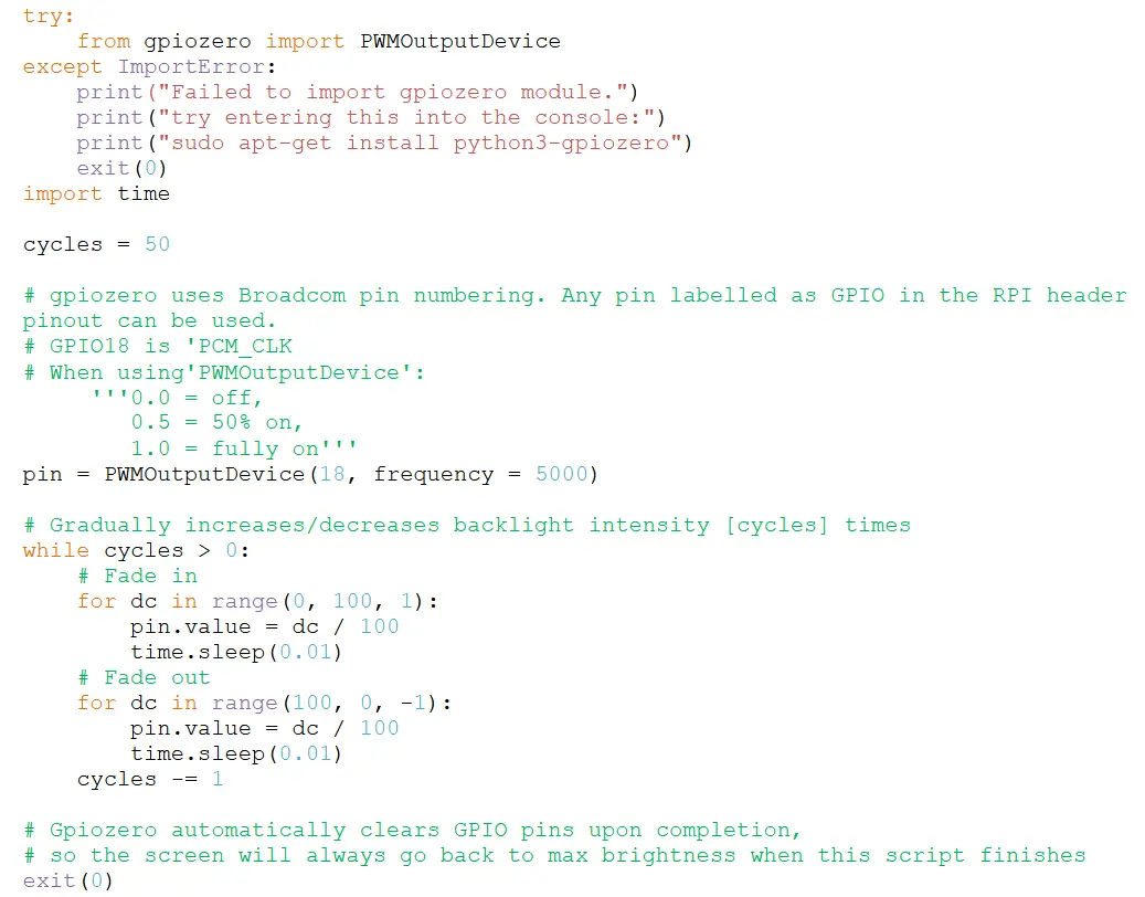
The GPIO pinout on Raspberry Pi 5 is identical to Raspberry Pi 4, but it uses a different hardware GPIO configuration, so the above method will not work. Instead, you will need to install the gpiozero python module.
sudo apt-get install python3-gpiozero
An example python script using gpiozero to control backlight PWM can be found on the FDI website at https://www.teamfdi.com/product-details/eli43-cp#software. You can also copy the code from below.

The ELI backlight can also be controlled from a Renesas Synergy S7G2 wired as shown in Figure 8. The software for Synergy can be found on our website at https://www.teamfdi.com/product-details/eli43- cp#software.
Mechanical View
- Tape used to secure the LCD to the PCB is: 3M VHB 4956 ½” width
- 4 screw holes on the ELI43-CP accept up to #4 size screws to mount ELI43-CP into an enclosure and to connect to the system ground.
- The exposed ground pads may be used to connect the ELI43-CP PCB directly to the LCD using copper or aluminum foil tape. This practice meets ESD requirements.


Support
Where to Get Help
Online technical support is available at https://www.teamfdi.com/support/
Useful Links
- Future Designs, Inc. Forums: https://www.teamfdi.com/forum
- ELI43-CP Product Page: https://www.teamfdi.com/product-details/eli43-cp
- ELI Software User’s Manual: https://fdiwebdocs.s3.us-east-2.amazonaws.com/2024/wp- content/uploads/ELI-Software-Users-Manual.pdf
- Tell us about your ELI experience: https://www.teamfdi.com/edid/#edidform
- EDID Information Page: https://www.teamfdi.com/edid/

Documents / Resources
 |
FDI ELI43-CP Long Life Plug and Play Embedded Displays [pdf] User Manual ELI43-CP Long Life Plug and Play Embedded Displays, ELI43-CP, Long Life Plug and Play Embedded Displays, Plug and Play Embedded Displays, Embedded Displays, Displays |