![]() Fuyansheng Electronics (Fujian) Co. LTD
Fuyansheng Electronics (Fujian) Co. LTD
FNI_IOL_310-S01-K024 00BH11
User Manual
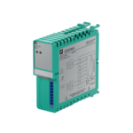
Connection diagram

- IO-Link Interface
- I/O connecting terminal
- Sensor supply 24V connecting terminal
- Sensor supply GND connecting terminal
- Indicator light:Input/Output
- Indicator light:IO-Link communication
- Indicator light:Sensor supply
- Indicator light:Actuator supply
IO-Link Interface definition
| IO-Link(Class A) | Pin | Description | Wire Color |
 |
1 | Sensor supply | Brown |
| 2 | Actuator supply | White | |
| 3 | GND | Blue | |
| 4 | C/Q IO-Link | Black | |
| 5 | Not connected | – |
IO-Link Data
3.1 Parameter
| Baud rate | COM2 (38.4kbit/s) |
| Cycle time(Minimum) | 3ms |
| Process data Cycle time | 3ms |
| Process data length | 2 Byte Input, 2 Byte Output |
3.2 Process data
| Digital I/O Pin | Input Data | Output Data |
| 1 | ByteO BitO | ByteO Bit() |
| 2 | ByteO Bitl | ByteO Bitl |
| 3 | ByteO Bit2 | ByteO Bit2 |
| 4 | ByteO Bit3 | ByteO Bit3 |
| 5 | ByteO Bit4 | ByteO Bit4 |
| 6 | ByteO Bit5 | ByteO Bit5 |
| 7 | ByteO Bit6 | ByteO Bit6 |
| 8 | ByteO Bit7 | ByteO Bit7 |
| 9 | Bytel BitO | Bytel BitO |
| 10 | Bytel Bitl | Bytel Bitl |
| 11 | Bytel Bit2 | Bytel Bit2 |
| 12 | Bytel Bit3 | Bytel Bit3 |
| 13 | Bytel Bit4 | Bytel Bit4 |
| 14 | Bytel Bit5 | Bytel Bit5 |
| 15 | Bytel Bit6 | Bytel Bit6 |
| 16 | Bytel Bit7 | Bytel Bit7 |
3.3 Identification/Parameter data
| SPDU | Object name | length | Range | Default value | ||
| Index | Sub Index | |||||
| / | / | Supplier ID | 2 | / | 0x0454 | |
| / | / | Device ID | 3 | / | Ox099CE2 | |
| Identification data | Ox10 | 0 | Supplier Name | 19 | Read only | FAS(Fujian)Co.,LTD |
| Ox11 | 0 | Supplier Text | 16 | www.fas-elec.com | ||
| 0x12 | 0 | Product name | 13 | FNI 10L-310-S01-K024 | ||
| 0x13 | 0 | Product ID | 5 | OOBH11 | ||
| 0x14 | 0 | Product Text | 44 | IO-Link DI/DO | ||
| 0x16 | 0 | Hardware Version | 3 | 20211105 | ||
| Ox17 | 0 | Firmware Version | 3 | 2.01 | ||
| Parameter data | 0x40 | 0 | Bit inversion | 2 | Ox0000∼ OxFFFF | Ox0000 |
| 0x41 | 0 | Input/Output Setting | 2 | Ox0000∼ OxFFFF |
Ox0000 | |
Note
- 0x40 Bit inversion : bit=0 not reverse, bit=1 reverse.
For example:
The external input is Ox0000. When 0x40 is Ox0000, the value is Ox0000 (not reverse), and when 0x40 is OxFFFF, the value is OxFFFF (reverse). - 0x41 Input/Output Setting: bit=0 input, bit=1 output.
3.4 Error code
Device application error code 0x80:
Additional code:
0x11 index not available
0x12 sub index not available
0x30 Value Out of range
3.5 Event
| Class/Qualifier | Code(High Bit + Low Bit) | |||||
| Pattern | Type | Instance | ||||
| Appear | Error | AL | Hardware | Power supply | Low voltage | U2=power supply |
| OxCO | 0x30 | 0x03 | 0x5000 | Ox0100 | Ox0010 | 0x0002 |
| OxF3 | 0x5112 | |||||
| Disappear | Error | AL | Hardware | Power supply | Low voltage | U2=power supply |
| 0x80 | 0x30 | 0x03 | 0x5000 | Ox0100 | Ox0010 | 0x0002 |
| OxB3 | 0x5112 | |||||
| Appear | Error | AL | Hardware | Power supply | Peripheral power supply | |
| OxCO | 0x30 | 0x03 | 0x5000 | Ox0100 | 0x0060 | |
| OxF3 | 0x5160 | |||||
| Disappear | Error | AL | Hardware | Power supply | Peripheral power supply | |
| 0x80 | 0x30 | 0x03 | 0x5000 | Ox0100 | 0x0060 | |
| OxB3 | 0x5160 | |||||
![]()
Documents / Resources
 |
FAS ELECTRONICS 00BH11 Digital Input-Output Pin [pdf] User Manual 00BH11 Digital Input-Output Pin, 00BH11, Digital Input-Output Pin, Input-Output Pin, Output Pin, Pin |