![]() LB6110ER Digital Output with Shutdown Input
LB6110ER Digital Output with Shutdown Input
User Manual
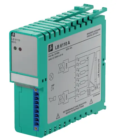
LB6110ER Digital Output with Shutdown Input
- 4-channel
- Outputs Ex ia
- Installation in Zone 2 or safe area
- Line fault detection (LFD)
- Positive or negative logic selectable
- Simulation mode for service operations (forcing)
- Permanently self-monitoring
- Output with watchdog
- Output with bus-independent safety shutdown
![]()
Function
The digital output features 4 independent channels.
The device can be used to drive solenoids, sounders, or LEDs.
Open and short-circuit line faults are detected.
The outputs are galvanically isolated from the bus and the power supply.
The output can be switched off via a contact. This can be used for bus-independent safety applications.
Connection

Technical Data
Slots
| Occupied slots | 2 |
| Functional safety related parameters | |
| Safety Integrity Level (SIL) | SIL 2 |
| Performance level (PL) | PL d |
| Supply | |
| Connection | backplane bus / booster terminals |
| Rated voltage | Ur 12 V DC , only in connection with the power supplies LB9*** |
| Input voltage range | U18.5 … 32 V DC (SELV/PELV) booster voltage |
| Power dissipation | 3 W |
| Power consumption | 0.15 W |
| Internal bus | ||
| Connection | backplane bus | |
| Interface | manufacturer-specific bus to standard com unit | |
| Digital output | ||
| Number of channels 4 | ||
| Suitable field devices | ||
| Field device | Solenoid Valve | |
| Field device [2] | audible alarm | |
| Field device [3] | visual alarm | |
| Connection | channel I: 1+, 2-; channel II: 3+, 4-; channel III: 5+, 6-; channel IV: 7+, 8- | |
| Internal resistor | Ri | max. 370 Ω |
| Current limit | Imax | 37 mA |
| Open loop voltage | Us | 24.5 V |
| Line fault detection | can be switched on/off for each channel via configuration tool also when turned off (every 2.5 s the valve is turned on for 2 ms) | |
| Short-circuit | < 100 Ω | |
| Open-circuit | > 15 kΩ | |
| Response time | 10 ms (depending on bus cycle time) | |
| Watchdog | within 0.5 s the device goes in safe state, e.g. after loss of communication | |
| Reaction time | 10 s | |
| Indicators/settings | ||
| LED indication, Power LED (P) green: supply Status LED (I) red: line fault , red flashing: communication error | ||
| Coding | optional mechanical coding via front socket | |
| Directive conformity | ||
| Electromagnetic compatibility | ||
| Directive 2014/30/EU | EN 61326-1:2013 | |
| Conformity | ||
| Electromagnetic compatibility: NE 21 | ||
| Degree of protection | IEC 60529 | |
| Environmental test | EN 60068-2-14 | |
| Shock resistance | EN 60068-2-27 | |
| Vibration resistance | EN 60068-2-6 | |
| Damaging gas | EN 60068-2-42 | |
| Relative humidity | EN 60068-2-78 | |
| Ambient conditions | ||
| Ambient temperature -20 … 60 °C (-4 … 140 °F) | ||
| Storage temperature | -25 … 85 °C (-13 … 185 °F) | |
| Relative humidity | 95 % non-condensing | |
| Shock resistance | shock type I, shock duration 11 ms, shock amplitude 15 g, number of shocks 18 | |
| Vibration resistance | frequency range 10 … 150 Hz; transition frequency: 57.56 Hz, amplitude/acceleration ± 0.075 mm/1 g; 10 cycles frequency range 5 … 100 Hz; transition frequency: 13.2 Hz amplitude/acceleration ± 1 mm/0.7 g; 90 minutes at each resonance | |
| Damaging gas | designed for operation in environmental conditions acc. to ISA-S71.04-1985, severity level G3 | |
| Mechanical specifications | ||
| Degree of protection | IP20 when mounted on backplane | |
| Connection | removable front connector with screw flange (accessory) wiring connection via spring terminals (0.14… 1.5 mm2) or screw terminals(0.08… 1.5 mm2) | |
| Mass | approx. 150 g | |
| Dimensions | 32.5 x 100 x 102 mm (1.28 x 3.9 x 4 inch) | |
| Data for application in connection with hazardous areas | ||
| EU-type examination certificate: PTB 03 ATEX 2042 X | ||
| Marking | 1 II (1)G [Ex ia Ga] IIC 1 II (1)D [Ex ia Da] IIIC 1 I (M1) [Ex ia Ma] I |
|
| Output | ||
| Voltage | Uo | 27.8 V |
| Current | Io | 90.4 mA |
| Power | Po | 629 mW |
| Internal capacitance | Ci | 1.65 nF |
| Internal inductance | Li | 0 MH |
| Certificate | PF 08 CERT 1234 X | |
| Marking | 1 II 3 G Ex nab IIC T4 Go | |
| Galvanic isolation | ||
| Output/power supply, internal bus | safe electrical isolation acc. to EN 60079-11, voltage peak value 375 V | |
| Directive conformity | ||
| Directive 2014/34/EU | EN IEC 60079-0:2018+AC:2020 EN 60079-11:2012 EN 60079-15:2010 |
|
| International approvals | ||
| ATEX approval | PTB 03 ATEX 2042 X | |
| IECEx approval | BVS 09.0037X | |
| Approved for | Ex nA [ia Ga] IIC T4 Gc [Ex ia Da] IIIC [Ex ia Ma] I |
|
| General information | ||
| System information | The module has to be mounted in appropriate backplanes (LB9***) in Zone 2 or outside hazardous areas. Here, observe the corresponding declaration of conformity. For use in hazardous areas (e. g. Zone 2, Zone 22 or Div. 2) the module must be installed in an appropriate enclosure. | |
| Supplementary information | EC-Type Examination Certificate, Statement of Conformity, Declaration of Conformity, Attestation of Conformity and instructions have to be observed where applicable. For information see www.pepperl-fuchs.com. | |
Assembly
Front view

Digital Output with Shutdown Input
Load calculation
Road = Field loop resistance
Use = Us – Ri x I.e.
I.e. = Us/(Ri + Road)
Characteristic Curve

![]() Refer to “General Notes Relating to Pepperl+Fuchs Product Information”.
Refer to “General Notes Relating to Pepperl+Fuchs Product Information”.
Pepperl+Fuchs Group
www.pepperl-fuchs.com
USA: +1 330 486 0002
pa-info@us.pepperl-fuchs.com
Germany: +49 621 776 2222
pa-info@de.pepperl-fuchs.com
Singapore: +65 6779 9091
pa-info@sg.pepperl-fuchs.com
Documents / Resources
 |
MISUMI LB6110ER Digital Output with Shutdown Input [pdf] User Manual LB6110ER Digital Output with Shutdown Input, LB6110ER, Digital Output with Shutdown Input, Output with Shutdown Input, Shutdown Input |


