![]() ALC
ALC
INSTALLATION INSTRUCTIONS
PRODUCT SAFETY
When using electrical equipment, basic safety precautions should always be followed, including the following:
![]() READ THESE INSTRUCTIONS BEFORE USING THIS PRODUCT.
READ THESE INSTRUCTIONS BEFORE USING THIS PRODUCT.
![]() Do not let power supply cords touch hot surfaces.
Do not let power supply cords touch hot surfaces.
![]() Do not mount near gas or electric heaters.
Do not mount near gas or electric heaters.
![]() Equipment should be mounted in locations and at heights where it will not readily be subjected to tampering by unauthorized personnel.
Equipment should be mounted in locations and at heights where it will not readily be subjected to tampering by unauthorized personnel.
![]() The use of accessory equipment is not recommended by Encelium as it may cause an unsafe condition.
The use of accessory equipment is not recommended by Encelium as it may cause an unsafe condition.
![]() Do not use this equipment for other than the intended use.
Do not use this equipment for other than the intended use.
![]() SAVE THESE INSTRUCTIONS.
SAVE THESE INSTRUCTIONS.
GETTING STARTED
Overview
The Area Lighting Controller (ALC) module interfaces between the Encelium X Lighting Control System and most electrical
loads. The ALC obtains operating power together with communication signals via the GreenBus™ control wire architecture.The module features an integrated relay to interrupt power to their loads which is rated up to 347V (CAD). Additionally, the module features an isolated dimming interface for installation as either NEC Class 1 or 2 circuit. The module will obtain its address during the commissioning process and no actions are required during installation.
The ALC is available in two models:
- Indoor
- Damp Rated
WIRED SYSTEM OVERVIEW
With Encelium X, you can control DALI devices exclusively or a mixture of GreenBus and DALI.
INSTALLATION
Before installing your ALC model, check to ensure you are using the appropriate rated version. The ALC is to be installed in dry,
indoor locations ONLY. For damp installations, ensure to use the ALC (damp rated). Damp locations are defined as: interior locations subject to moderate degrees of moisture, such as some basements, some barns, some cold-storage warehouses, and the like, and partially protected locations under canopies, marquees, roofed open porches, and the like.
MOUNTING OPTIONS
- Option 1 — Luminaire Mount
The ALC interface (purple and pink wires) is a galvanically isolated 0-10V circuit such that it may be wired as NEC Class 1 or 2.
- Option 2 —Junction Box Mount
For some installations, a junction box may be required. It is recommended to securely mount the ALC to the junction box using an available PG-7 (0.5 inch) trade-size knockout. No retainer nut is needed because the module has integrated retention clips built into the knockout nipple.
ELECTRICAL CONNECTIONS
- Non-Dimmable Luminaire Wiring
Connect line voltage AC power to ALC and ballasts.
- Dimmable Luminaire Wiring
Connect line voltage AC power to ALC and ballasts. Dimming wires (Purple and Pink) from ALC can be run either as Class 1 or Class 2 (consult applicable local electrical and building codes).
- Junction Box Wiring

- ALC Wiring
GreenBus communication wiring is still accessible from the outside of the luminaire while all necessary wiring to the electronic dimming ballast is available on the inside.
The ALC is made from tested material to be used in plenum or “plenum rated” areas. All wiring is rated 600V, 105ºC (221ºF) for use in light luminaires.
To control multiple ballasts, parallel all ballast input wires (line, neutral, and control wires purple and pink). It is recommended to observe the maximum ratings of the ALC to ensure maximum ratings are not exceeded. Notes: Recommended Relay switching capacity, 120–347V, 20A maximum. Recommended Dimming signal capacity, 0-10V, 30mA maximum (sinking).
Due to the internal relay, power feed to luminaire may be live even if lights are off. Turn off power at circuit breaker or fuse before installing or servicing module. Observe lockout procedures. - GreenBus
GreenBus is a low-cost, high reliability communication means to report information back to the Encelium X and Encelium Edge Lighting Control Systems.
The GreenBus wiring can originate at the Wired Manager and propagates in a daisy-chain from module to module (or other compatible equipment). When tethering the GreenBus wiring can also originate from a GB port on a Wireless Area Lighting Control Module (WALC) or a Wireless Control Module (WCM).
The GreenBus wires must be used with proprietary connectors supplied. Insert the connectors to the ALC GB ports.
 GreenBus must be laid out as per supplied system layout drawing. If changes are required, determine an optimum wiring path utilizing the supplied cables, based on the position of the devices
 To remove the wires, use a flat head screwdriver to release the wires from the terminal blocks.
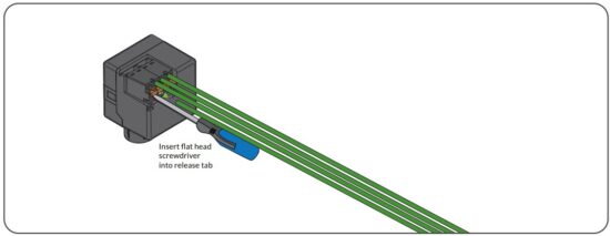
Notes: Relay Contact; recommended relay switching capacity 120 VAC, 450 W or 277 VAC, 900 W maximum.
If the devices are connected with a method other than daisy-chain, this must be indicated to an Encelium Representative for approval before wiring.
![]() GreenBus uses proprietary connectors and jacks for ease of installation only. GreenBus is a proprietary standard.
GreenBus uses proprietary connectors and jacks for ease of installation only. GreenBus is a proprietary standard.
Connect to Encelium Lighting Control System only. Do not connect to other circuits.
INSTALLATION TESTING
Installer can quickly test if the devices have been wired correctly by pressing any button on the wallstation or the sensor which triggers all the load controllers on the channel to change the dimming level by 25%. Every press will trigger this function to enable testing of the AC line wiring, dimming wiring and communication integrity over the GreenBus lines.
MANUAL PAIRING
Installers can easily pair devices in a room or a zone to gain manual control (on, off and dimming) and occupancy time outs.
Holding any buttons on a wallstation or sensor for 10 seconds enters the system in the Manual Pairing mode. The system then guides the user by blinking the load controllers on the GreenBus wiring scheme as a means of identifying and pairing them to the wallstation or sensor.
![]() © Copyright 2024 Legrand All Rights Reserved.
© Copyright 2024 Legrand All Rights Reserved.
080420r1 01/24
encelium.com
Documents / Resources
 |
ENCELIUM ALC Wireless Area Lighting Controller [pdf] Installation Guide ALC, ALC Sensor, ALC Wireless Area Lighting Controller, ALC, Wireless Area Lighting Controller, Area Lighting Controller, Lighting Controller, Controller |