Contents
hide
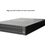
Edge-core AS9716-32D 32 Port 400G Data Center Spine Switch

Package Contents

- 32-Port 400G Data Center Spine Switch AS9716-32D
- Rack mounting kit—2 front-post brackets, 2 rear-post brackets, 20 screws, and 2 ear-locking screws
- Power cord (included with AC PSUs only)
- Console cable—RJ-45 to DE-9
- Documentation—Quick Start Guide (this document) and Safety and Regulatory Information
Overview

- Timing ports: 10 MHz, 1PPS, ToD
- 32 x 400G QSFP-DD ports
- Management ports: 1 x 1000BASE-T RJ-45, 2 x 10G SFP+, RJ-45 console, USB
- Product label
- 2 x AC PSUs
- 6 x fan trays
- 2 x grounding screws
- PS1/PS2: Green (OK), Amber (fault)
- Diag: Green (OK), Amber (no OS or fault)
- Fan: Green (OK), Amber (fault)
- Loc: Flashing Amber (switch locator) Reset Button

Port LEDs
- QSFP-DD LEDs
- 400G: 1 LED Blue
- 200G Breakout: 1 LED White,
- 1-2 LEDs Green
- 100G Breakout: 1-4 LEDs
- Green 50G Breakout: 1 LED Cyan
- SFP+ 10G Mgmt
- LEDs Green (10G)
- Amber (1G)
- RJ-45 Mgmt LED Green (link/activity)

FRU Replacement

PSU Replacement
- Remove the power cord.
- Press the release latch and remove the PSU.
- Install replacement PSU with matching airflow direction.
Fan Tray Replacement 
- Pull the handle release latch.
- Remove fan tray from the chassis.
- Install replacement fan with matching airflow direction.
Airflow Reversal
 F2B Airflow
Remove front-to-back (F2B) airflow fan trays (red handles) and PSUs (red release latches).
- B2F Airflow
Install back-to-front (B2F) airflow fan trays (blue handles) and PSUs (blue release latches).
Installation
- Warning: For a safe and reliable installation, use only the accessories and screws provided with the AS9716-32D. Use of other accessories and screws could result in damage to the unit. Any damages incurred by using unapproved accessories are not covered by the warranty.
- Caution: The switch includes plug-in power supply (PSU) and fan tray modules that are installed into its chassis. Make sure all installed modules have a matching airflow direction (front-to-back or back-to-front).
Note: The switch has the Open Network Install Environment (ONIE) software installer preloaded on the switch, but no switch software image. Information about compatible switch software can be found at www.edge-core.com.
Note: The switch drawings in this document are for illustration only and may not match your particular switch model.
Mount the Switch
Caution: This device must be installed in a telecommunications room or a server room.

- Attach the Brackets
Use the included screws to attach the front- and rear-post brackets.
- Mount the Switch
Mount the switch in the rack and secure it with rack screws.
- Lock the Rear-Post Brackets
Use the included screws to lock the position of the rear-post brackets.
Connect Power
 AC Power
Install one or two AC PSUs and connect them to an AC power source.
Make Network Connections
 QSFP-DD Ports
- Install transceivers and then connect fiber optic cabling to the transceiver ports.
- Alternatively, connect DAC or AOC cables directly to the QSFP-DD slots.
Connect Timing Ports
 1PPS and 10 MHz Ports
Use coax cables to connect the 1-pulse-per-second (1PPS) and 10 MHz IN/OUT ports to other synchronized devices.
ToD Port
Use a shielded cable to connect the Time-of-Day (ToD) port to other devices that use ToD synchronization signals.
Make Management Connections 
- 10/100/1000M RJ-45 Management Port Connect Cat. 5e or better twisted-pair cable.
- 10G SFP+ Management Ports
- Install transceivers and then connect fiber optic cabling to the transceiver ports.
RJ-45 Console Port
Connect the included console cable and then configure the serial connection: 115200 bps, 8 characters, no parity, one stop bit, 8 data bits, and no flow control.
Hardware Specifications
- Switch Chassis
- Size (WxDxH) 438.4 x 536 x 43.1 mm (17.26 x 21.1 x 1.7 in.)
- Weight 11.06 kg (24.38 lb), with 2 PSUs and 6 fans installed
- Temperature Operating: 0° C to 45° C (32° F to 113° F)
- Storage: -40° C to 70° C (-40° F to 158° F)
- Humidity Operating: 5% to 95% (non-condensing)
- Power Consumption 1300 Watts maximum
AC PSU
- Input Power 100–120 VAC, 50–60 Hz, 12 A max.
- Rating 200–240 VAC, 50–60 Hz, 7.5 A max. 190–310 VDC, 8–5 A
Regulatory Compliances
- Emissions EN 55032 Class A
- EN 61000-3-2
- EN 61000-3-3
- FCC Class A
- VCCI Class A
- BSMI Class A
- ICES-003 Class A
- AS/NZS CISPR32 Class A
- Immunity EN 55024/55035
- IEC 61000-4-2/3/4/5/6/8/11
- Safety UL (CSA 22.2 No 62368-1 & UL62368-1) CB (IEC/EN60950-1 & IEC/EN 62368-1) BSMI CNS15598-1
FAQ
- Q: Where can I find compatible switch software for AS9716-32D?
A: Information about compatible switch software can be found at www.edge-core.com. - Q: How do I connect timing ports for synchronization?
A: Use coax cables to connect the 1PPS and 10 MHz ports to other synchronized devices. Use a shielded cable for the ToD port.
Documents / Resources
 |
Edge-core AS9716-32D 32 Port 400G Data Center Spine Switch [pdf] User Guide AS9716-32D, AS9716-32D 32 Port 400G Data Center Spine Switch, 32 Port 400G Data Center Spine Switch, 400G Data Center Spine Switch, Center Spine Switch, Spine Switch, Switch |