Edge-corE AIS800-32D 800 Gigabit AI and Data Center Ethernet Switch

Package Contents

- AIS800-32D switch
- Slide-rail mounting kit—2 rack slide-rails and install guide
- AC power cord (included with AC PSUs only)
- DC power cord (included with DC PSUs only)
- Ground plate
- Ground lug (optional)
- Documentation—Quick Start Guide (this document) and Safety and Regulatory Information
Overview
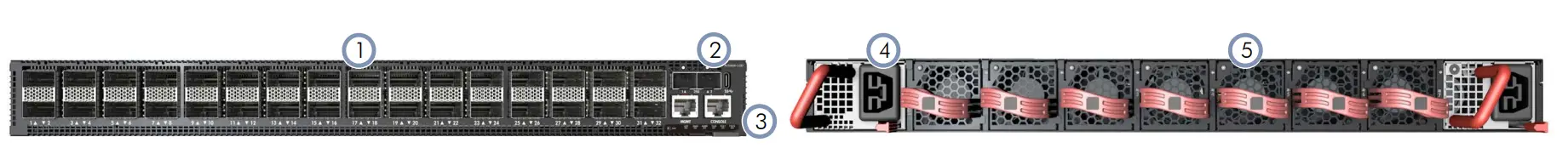
- 32 x 800G QSFP-DD800 ports
- Management Ports: 2 x 25G SFP28, 1 x 1000BASE-T RJ-45, RJ-45 console, USB
- System LEDs
- 2 x AC or DC PSUs
- 7 x fan trays
System LEDs/Buttons
- QSFP-DD800 LEDs: Yellow (800G), Blue (400G), White (200G), Green (100G)
- SFP28 LEDs: Green (link/activity)
- RJ-45 MGMT LEDs: Left: Green (link/act), Right: Green (1G/ 100M)
- System LEDs:
LOC: Flashing Green (switch locator)
DIAG: Green (OK), Red (fault)
ALRM: Red (fault)
FAN: Green (OK), Red (fault)
PSU1/PSU2: Green (OK), Red (fault) - RST: Reset button
FRU Replacement
PSU Replacement
- Remove the power cord.
- Press the release latch and remove the PSU.
- Install replacement PSU with matching airflow direction.

Fan Tray Replacement
- Pull the handle release latch.
- Remove the fan tray from the chassis.
- Install a replacement fan with a matching airflow direction.
Caution: During switch operation, fan replacement should be completed within two minutes to prevent the switch shutting down due to its built-in over-temperature protection.
Caution: The device must be installed in a restricted-access location.
Note: The device has the Open Network Install Environment (ONIE) software installer preloaded, but no device software image.
Note: The drawings in this document are for illustration only and may not match your particular model.
Mount the Device
Caution: This device must be installed in a telecommunications room or a server room where only qualified personnel have access
Installation
Warning: For a safe and reliable installation, use only \the accessories and screws provided with the device. Useof other accessories and screws could result in damage to the unit. Any damages incurred by using unapproved accessories are not covered by the warranty.
Using the Slide-Rail Kit
Follow the instructions in the install guide provided in the slide-rail kit to mount the device in a rack.
Note: Stability hazard. The rack may tip over causing serious personal injury.
Before extending the rack to the installation position, read the installation instructions.
Do not put any load on the slide-rail-mounted equipment in the installation position.
Do not leave the slide-rail-mounted equipment in the installation position.
Ground the Device
Verify Rack Ground
Ensure the rack on which the device is to be mounted is properly grounded and in compliance with ETSI ETS 300 253. Verify that there is a good electrical connection to the grounding point on the rack (no paint or isolating surface treatment).
Attach Grounding Wire
Use two M5 screws to attach the ground plate to the side of the device. Attach a grounding wire with a grounding lug (Panduit LCCF6-14A-L or equivalent, not included) to the ground plate using two M6 screws and washers. The grounding lug should accommodate #6 AWG stranded copper wire (green with yellow stripe, not included).
Caution: The earth connection must not be removed unless all supply connections have been disconnected.
Connect Power
Install one or two AC or DC PSUs and connect them to an AC or DC power source.
Note: When using only one AC PSU to power a fully loaded system, be sure to use a high-voltage source (200–240 VAC).

- Ground
- -40 – -72 VDC
- DC return
Caution: Use a UL/IEC/EN 60950-1 and/or 62368-1 certified power supply to connect to a DC converter
Caution: All DC power connections should be performed by a qualified professional.
Note: Connect an external DC power source to the PSUs. Or, connect to a no-tolerance DC mains supply with a UL/CSAapproved circuit breaker rated for 80A or as required by local electrical code.
Note: Use #6 AWG / 13.3 mm2 90°C-rated copper wire (for a -40 to -72 VDC PSU) to connect to a DC PSU. Tighten the screws to a torque of 2.4 N.m (21.2 lbf.in).
Make Network Connections
800G QSFP-DD800 Ports
Install transceivers and then connect fiber optic cabling to the transceiver ports. Alternatively, connect DAC or AOC cables directly to the slots.
Make Management Connections
25G SFP28 In-Band Management Ports
Install transceivers and then connect fiber optic cabling to the transceiver ports.
10/100/1000M RJ-45 Out-of-Band Management Port
Connect Cat. 5e or better twisted-pair cable.
RJ-45 Console Port
Use an RJ-45-to-DB-9 null-modem console cable (not included) to connect to a PC running terminal emulator software. Use a USB-to-male DB-9 adapter cable (not included) for connections to PCs that do not have a DB-9 serial port. Configure the serial connection: 115200 bps, 8 characters, no parity, one stop bit, 8 data bits, and no flow control.
Console cable pinouts and wiring:
Device’s RJ-45 Console Null Modem PC’s 9-Pin DTE Port
- 6 RXD (receive data) <————— 3 TXD (transmit data)
- 3 TXD (transmit data) —————> 2 RXD (receive data)
- 4,5 SGND (signal ground) —————– 5 SGND (signal ground)
Hardware Specifications
Switch Chassis
- Size (WxDxH) 438.4 x 589 x 44 mm (17.26 x 23.19 x 1.73 in.)
- Weight 14.69 kg (32.39 lb), with 2 PSUs and 7 fans installed
- Temperature Operating: 0° C to 40° C (32° F to 104° F)
- Storage: -40° C to 70° C (-40° F to 158° F)
- Humidity Operating: 5% to 95% (non-condensing)
System Input Rating
- AC Input 200-240 VAC, 50/60Hz, 15 A max. per PS
- DC Input -48 – -60 VDC, 53 A max. per PS
- Regulatory Compliances
- Emissions EN 55032 Class A
- EN 300 386 Class A
- EN 61000-3-2 Class A
- EN 61000-3-3
- VCCI Class A
- AS/NZS Class A
- ICES-003 Class A
- FCC Class A
- BSMI Class A
- Immunity EN 55024/55035
- EN 300 386
- EN/IEC 61000-4-2/3/4/5/6/8/11
- Safety UL (CSA 22.2 No 62368-1 & UL62368-1)
- CB (IEC/EN 62368-1)
- BSMI CNS 15598-1
FAQ
- Q: How do I connect to the management ports?
- A: Use the provided console cable and refer to the pinout guide for proper connection.
- Q: What should I do if a system LED indicates a fault?
- A: Check the corresponding component (e.g., PSU, fan) and follow the replacement instructions if necessary.
- Q: Can I use both AC and DC power supplies simultaneously?
- A: Yes, you can install and use either one or both AC or DC power supplies based on your requirements.
Documents / Resources
 |
Edge-corE AIS800-32D 800 Gigabit AI and Data Center Ethernet Switch [pdf] User Guide AIS800-32D, AIS800-32D 800 Gigabit AI and Data Center Ethernet Switch, 800 Gigabit AI and Data Center Ethernet Switch, AI and Data Center Ethernet Switch, Data Center Ethernet Switch, Ethernet Switch |