![]()
User Manual of ED-GWL2010

ED-GWL2010
An indoor light gateway based on Raspberry Pi 4B
EDA Technology Co.,Ltd
May 2024
EDA Technology Co.,LTD– Electronics Development Accelerator
ED-GWL2010 Indoor Light Gateway Based
Copyright Statement
ED-GWL2010 and its related intellectual property rights are owned by EDA Technology Co., Ltd.
EDA Technology Co., Ltd owns the copyright of this document and reserves all rights. Without the written permission of EDA Technology Co., Ltd, no part of this document may be modified, distributed or copied in any way or form.
Disclaimers
EDA Technology Co., Ltd does not guarantee that the information in this manual is up to date, correct, complete or of high quality. EDA Technology Co., Ltd also does not guarantee the further use of this information. If the material or non-material related losses are caused by using or not using the information in this manual, or by using incorrect or incomplete information, as long as it is not proved that it is the intention or negligence of EDA Technology Co., Ltd, the liability claim for EDA Technology Co., Ltd can be exempted. EDA Technology Co., Ltd expressly reserves the right to modify or supplement the contents or part of this manual without special notice.
Product Overview
ED-GWL2010 is an indoor light gateway designed based on Raspberry Pi 4B. This product uses the new generation of SX1302 and SX1303 baseband chip LoRa gateway modules, which have the characteristics of long transmission distance, large node capacity and high receiving sensitivity. In addition, this gateway has strong performance, light structure, and simple deployment, which can greatly simplify and shorten your development threshold and design time.
1.1 Target Application
- LoRa intelligent gateway
- Smart manufacturing
- Smart city
- Smart transportation
1.2 Specifications and Parameters
| Function | Parameters |
| CPU | Broadcom BCM2711, quad core Arm Cortex-A72 (ARM v8) 64-bit SoC @ 1.5GHz |
| Memory | Options for 1GB, 2GB, 4GB, 8GB LPDDR4-3200 SDRAM |
| OS | Compatible with official Raspberry Pi OS |
| SD card | Options for 32GB, 64GB |
| Ethernet | lx Gigabit Ethernet |
| Wi-Fi/Bluetooth | 2.4GHz & 5GHz dual-band Wi-Fi and Bluetooth 5.0 |
| LoRa Frequency | Support optional 868MHz(EU868)/915MHz(US915)/470MHz(CN470) |
| User Button | Support custom function |
| RGB LED | Support multiple custom displays |
| Power Supply | DC 12V/2A |
| Internal 10 | 2x Micro-HDMI lx CSI, support extended connection to Camera lx DSI, support extended connection to Raspberry Pi 7-inch LCD screen 2x USB 2.0, type A connector 2x USB 3.0, type A connector |
| Expansion Performance | Built-in Crypto Authentication |
| Case Material | Metal Case |
| Dimensions | 95mm(W) x 95mm(D) x 24mm(H) |
| Antenna | Supports optional Wi-Fi/BT external antenna Standard LoRa extemal antenna |
| Working Temperature | -25 – 50 C |
1.3 System Diagram

1.4 Functional Layout

| Item | Function Description | Item | Function Description |
| Al | Mini PCIe | A2 | Power interface |
| A3 | RGB LED | A4 | User-defined Button |
| AS | Gigabit Ethernet | A6 | USB 3.0 |
| A7 | USB 2.0 | A8 | 3.5mm audio jack connector |
| A9 | CSI | A10 | Micro HDMI |
| All | Micro HDMI | Al2 | Pi4 power interface (no need to use) |
| A13 | DSI | / | / |

| Item | Function Description | Item | Function Description |
| B1 | Debug UART Port | B2 | SD Card Slot |
1.5 Packing List
- 1x ED-GWL2010 Unit
- [option]1x LoRa Antenna
- [optional]1x 2.4GHz&5GHz Wi-Fi/BT Antenna
1.6 Ordering Code

Example
P/N: ED-GWL2010-232-CN
Configuration: An indoor light gateway based on Raspberry Pi 4, with 2GB DDR, 32GB SD card and CN470 LoRa frequency.
Quick Start
2.1 Equipment List
- 1x ED-GWL2010 Unit
- 1x Wi-Fi/BT external antenna
- 1x LoRa external antenna
- 1x network cable
- 1x 12V@2A power supply
2.2 Hardware Connection
- Install the Wi-Fi/BT external antenna.
- Install LoRa external antenna.
- Insert the network cable into the Ethernet port, and the network cable is connected with network devices such as routers and switches that can access the Internet.
- Plug in the DC power input port (+12V DC) of ED-GWL2010 and supply power to the power adapter.
ED-GWL2010 does not have a power switch. After connecting to the power supply, the system will start to boot.
2.3.1 Raspberry Pi OS (Lite)
If you use the OS provided by us, after the system starts, you will automatically log in with the user name pi, and the default password is raspberry.

If you use the official OS, and OS is not configured before flashing to SD card, the configuration window will appear when you start it for the first time. You need to configure the keyboard layout, set the username and the corresponding password in turn.
- Set the configuration keyboard layout

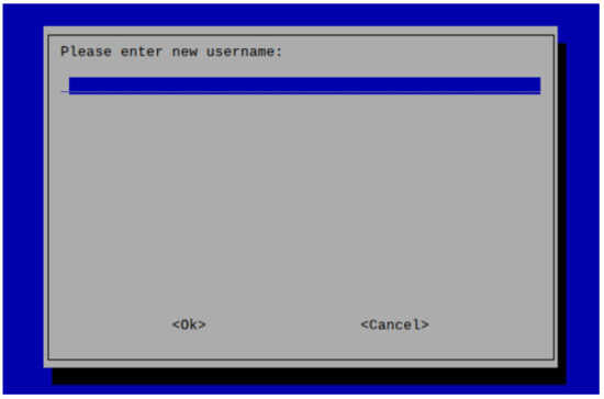
- Create a new user name
Then set the password corresponding to the user according to the prompt, and enter the password again for confirmation. At this point, you can log in with the user name and password you just set.
2.3.2 Enable SSH
All the OS we provide have been enabled the SSH. If you use the official OS, you need to use a method to enable the SSH function.
2.3.2.1 Enable SSH via raspi-config command
- Execute “sudo raspi-config” command
- Choose 3 Interface Options
- Choose I2 SSH
- Would you like the SSH server to be enabled? Select Yes
- Choose Finish
2.3.2.2 Add Empty File to Enable SSH
Creat an empty file named ssh in the boot partition, and the SSH will be automatically enabled after the device is powered on.
2.3.3 Get The Device IP
- After the device is started, if the display screen is connected, you can use the ifconfig command to view the current device IP.
- After the device is started, if there is no display connected, you can check the IP assigned to the device through the router.
- After the device is started, if there is no display screen connected, you can download the Nmap tool to scan the IP under the current network.
Nmap supports Linux, macOS, Windows and other platforms. If you want to use nmap to scan the network segments from 192.168.3.0 to 255, you can use the following command:
nmap -sn 192.168.3.0/24
After waiting for a period of time, the result will be output:
Starting Nmap 7.92 ( https://nmap.org ) at 2022-12-30 21:19 中国标准时间
Nmap scan report for 192.168.3.1 (192.168.3.1)
Host is up (0.0010s latency).
MAC Address: XX:XX:XX:XX:XX:XX (Phicomm (Shanghai))
Nmap scan report for DESKTOP-FGEOUUK.lan (192.168.3.33)
Host is up (0.0029s latency).
MAC Address: XX:XX:XX:XX:XX:XX (Dell)
Nmap scan report for 192.168.3.66 (192.168.3.66)
Host is up.
Nmap done: 256 IP addresses (3 hosts up) scanned in 11.36 seconds
Wiring Guide
3.1 Internal I/O
3.1.1 Micro-SD Card
ED-GWL2010 contains a micro-SD card slot. Before powering on the device, please insert the micro-SD card with OS into the micro-SD card slot.
3.1.2 Antenna
ED-GWL2010 contains two external antennas, one is a Wi-Fi/BT antenna and the other is a LoRa antenna, which can be distinguished by the antenna labels.

According to the silk-screen instructions on the antenna interface on the device side, install the Wi-Fi/BT antenna on the left and the LoRa antenna on the right as shown in the above figure.
Software Operation Guide
4.1 Button
ED-GWL2010 contains a user-defined button inside the device, which is connected to the GPIO23 pin of CPU. It is at a high level by default. When the button is pressed, the pin is at a low level.
You can use the raspi-gpio command to test.
- Query the GPIO23 pin when the button is not pressed.
raspi-gpio get 23
GPIO 23: level=1 fsel=0 func=INPUT
level of 1 indicates that the GPIO23 pin is high.
- Query the GPIO23 pin When the button is pressed.
raspi-gpio get 23
GPIO 23: level=0 fsel=0 func=INPUT
level of 0 indicates that the GPIO23 pin is low.
4.2 LED Indication
ED-GWL2010 includes an RGB 3-color LED indicator, and the corresponding GPIO pins are as follows:
| RGB LED PIN | GPIO |
| Blue | GPIO16 |
| Green | GPIO20 |
| Red | GPIO21 |
When the GPIO output is low, the corresponding LED is valid.
You can use the raspi-gpio command to operate, and the configuration parameter is op, which means output setting, dl setting pin is low level, and dh setting pin is high level.
The LED is displayed in blue.
sudo raspi-gpio set 16 op dl
sudo raspi-gpio set 20 op dh
sudo raspi-gpio set 21 op dh
The LED is displayed in green.
sudo raspi-gpio set 16 op dh
sudo raspi-gpio set 20 op dl
sudo raspi-gpio set 21 op dh
The LED is displayed in red.
sudo raspi-gpio set 16 op dh
sudo raspi-gpio set 20 op dh
sudo raspi-gpio set 21 op dl
The LED is displayed in yellow.
sudo raspi-gpio set 16 op dh
sudo raspi-gpio set 20 op dl
sudo raspi-gpio set 21 op dl
4.3 Ethernet Configuration
ED-GWL2010 includes one adaptive 10/100/1000M Ethernet interface.
The official OS of Raspberry Pi uses dhcpcd as the network management tool by default.
Static IP can be set by modifying “/etc/dhcpcd.conf”. For example, eth0 can be set, and users can set wlan0 and other network interfaces according to their different needs.
interface eth0
static ip_address=192.168.0.10/24
static routers=192.168.0.1
static domain_name_servers=192.168.0.1 8.8.8.8 fd51:42f8:caae:d92e::1
4.4 Wi-Fi
ED-GWL2010 supports 2.4GHz&5GHz IEEE 802.11 b/g/n dual-band Wi-Fi.
The official OS of Raspberry Pi uses dhcpcd as the network management tool by default.
- Execute “sudo raspi-config” command.
- Choose 1 System Options
- Choose S1 Wireless LAN
- Select your country in the “Select the country in which the pi is to be used” window, and then select OK. This prompt only appears when setting up Wi-Fi for the first time.
- Please enter SSID,input WIFI SSID name.
- Please enter passphrase. Leave it empty if none, input password and then restart the device。
4.5 Bluetooth
ED-GWL2010 supports Bluetooth 5.0 and Bluetooth Low Energy (BLE). The Bluetooth function is enabled by default.
Bluetoothctl can be used to scan, pair and connect Bluetooth devices. Please refer to the ArchLinuxWiki-Bluetooth guide to configure and use Bluetooth.
4.5.1 Basic Configuration Commands
| Command | Function Description |
| bluetoothctl scan on | Enable Bluetooth scanning |
| bluetoothctl scan off | Disable Bluetooth scanning |
| bluetoothctl discoverable on | Enable Bluetooth discovery (which can be discovered by the other party) |
| bluetoothctl discoverable off | Disable Bluetooth discovery |
| bluetoothctl trust device MAC | Trust device |
| bluetoothctl connect device MAC | Connect device |
| bluetoothctl disconnect device MAC | Disconnect device |
4.5.2 Configuration Example
This chapter introduces how to configure Bluetooth through a configuration example.
Preparation:
The Bluetooth to be paired has been enabled and its name has been determined.
Steps:
- Enter the Bluetooth view.
sudo bluetoothctl - Enable bluetooth.
power on - Scan Bluetooth device.
scan on
Returned display information:
Discovery started
[CHG] Controller B8:27:EB:85:04:8B Discovering: yes
[NEW] Device 4A:39:CF:30:B3:11 4A-39-CF-30-B3-11 - Find the name of the turned-on Bluetooth device.
devices
Returned display information:
Device 6A:7F:60:69:8B:79 6A-7F-60-69-8B-79
Device 67:64:5A:A3:2C:A2 67-64-5A-A3-2C-A2
Device 56:6A:59:B0:1C:D1 Lefun
Device 34:12:F9:91:FF:68 test - Pairing target devices.
pair 34:12:F9:91:FF:68
34:12:F9:91:FF:68 is target device’s device_MAC
Returned display information:
Attempting to pair with 34:12:F9:91:FF:68
[CHG] Device 34:12:F9:91:FF:68 ServicesResolved: yes
[CHG] Device 34:12:F9:91:FF:68 Paired: yes Pairing successful
 TIP:
TIP:
The Bluetooth device to be connected also needs to confirm the pairing request, otherwise the pairing will fail. - Add as trusted device.
trust 34:12:F9:91:FF:68
34:12:F9:91:FF:68 is target device’s device_MAC
Returned display information:
[CHG] Device 34:12:F9:91:FF:68 Trusted: yes
Changing 34:12:F9:91:FF:68 trust succeeded
4.6 LoRaWAN
ED-GWL2010 supports LoRaWAN open source service platform ChirpStack. Please refer to the following steps for installation and configuration.
4.6.1 Install LoRa Service and ChirpStack Client
We install it by APT.
Add edatec APT warehouse
$ curl -sS https://apt.edatec.cn/pubkey.gpg | sudo apt-key add –
$ echo “deb https://apt.edatec.cn/raspbian stable main” | sudo tee /etc/apt/sources.list.d/edatec.list
$ sudo apt update
$ sudo apt install -y ed-gwl-pktfwd
Install ChirpStack
$ sudo apt install -y apt-transport-https dirmngr
$ sudo apt-key adv –keyserver keyserver.ubuntu.com –recv-keys 1CE2AFD36DBCCA00
$ echo “deb https://artifacts.chirpstack.io/packages/4.x/deb stable main” | sudo tee/etc/apt/sources.list.d/chirpstack.list
$ sudo apt update
$ sudo apt install -y chirpstack-gateway-bridge
Modify “config.txt”
[all]
dtparam=i2c_arm=on
dtparam=spi=on
gpio=16=op,dl
gpio=20=op,dl
gpio=21=op,dl
Modify “/etc/modules”, add i2c-dev at the end
i2c-dev
ED-GWL2010 use i2c-1 and spidev0.0。
4.6.2 Configuring LoRa Service
4.6.2.1 Pktfwd Config
# update region
$ cat /etc/ed_gwl/region
EU868 # EU868 / US915
pktfwd use 1700 as UDP port
$ sudo systemctl restart ed-pktfwd.service
4.6.2.2 chirpstack-gateway-bridge Configuration
You can use nano to edit the configuration file “chirpstack-gateway-bridge.toml”.
$ sudo nano /etc/chirpstack-gateway-bridge/chirpstack-gateway-bridge.toml
# This configuration provides a Semtech UDP packet-forwarder backend and
# integrates with a MQTT broker. Many options and defaults have been omitted
# for simplicity.
#
# See https://www.chirpstack.io/gateway-bridge/install/config/ for a full
# configuration example and documentation.
# Gateway backend configuration.
[backend]
# Backend type.
type=”semtech_udp”
# Semtech UDP packet-forwarder backend.
[backend.semtech_udp]
# ip:port to bind the UDP listener to
#
# Example: 0.0.0.0:1700 to listen on port 1700 for all network interfaces.
# This is the listener to which the packet-forwarder forwards its data
# so make sure the ‘serv_port_up’ and ‘serv_port_down’ from your
# packet-forwarder matches this port.
udp_bind = “0.0.0.0:1700″
# Integration configuration.
[integration]
# Payload marshaler.
#
# This defines how the MQTT payloads are encoded. Valid options are:
# * protobuf: Protobuf encoding
# * json: JSON encoding (easier for debugging, but less compact than ‘protobuf’)
marshaler=”protobuf”
# MQTT integration configuration.
[integration.mqtt]
# Event topic template.
event_topic_template=”eu868/gateway/{{ .GatewayID }}/event/{{ .EventType }}”
# Command topic template.
command_topic_template=”eu868/gateway/{{ .GatewayID }}/command/#”
# MQTT authentication.
[integration.mqtt.auth]
# Type defines the MQTT authentication type to use.
#
# Set this to the name of one of the sections below.
type=”generic”
# Generic MQTT authentication.
[integration.mqtt.auth.generic]
# MQTT server (e.g. scheme://host:port where scheme is tcp, ssl or ws)
server=”tcp://127.0.0.1:1883″
# Connect with the given username (optional)
username=””
# Connect with the given password (optional)
password=””
“event_topic_template / command_topic_template” needs to modify the prefix with gateway zone.
Example:
event_topic_template=”eu868/gateway/{{ .GatewayID }}/event/{{ .EventType }}”
If you use the US915 or CN470 module, please change the prefix “eu868” to “us915_0/cn470_10”.
event_topic_template=”us915_0/gateway/{{ .GatewayID }}/event/{{ .EventType }}”
The server address of “integration.mqtt” needs to be your chirpstack server.
$ sudo systemctl restart chirpstack-gateway-bridge.service
After modify “chirpstack-gateway-bridge.toml” config, need restart “chirpstack-gateway-bridge” service.
4.6.2.3 Reboot
$ sudo reboot
4.6.3 Install ChirpStack Server
To configure a cloud server, docker needs to be installed on the server before configuration.
Install docker:https://docs.docker.com/get-docker/
Install docker-compose
sudo apt install docker-compose
4.6.3.1 Config chirpstack-docker
We use docker container to deploy ChirpStack server.
$ git clone https://github.com/chirpstack/chirpstack-docker.git
Need to config “docker-compose.yml” of “chirpstack-docker”.
$ cd chirpstack-docker
$ nano docker-compose.yml
# Remove the chirpstack-gateway-bridge, because we run the bridge on gateway.
Delete the red font part.
$ nano docker-compose.yml
version: “3”
services:
chirpstack:
image: chirpstack/chirpstack:4
command: -c /etc/chirpstack
restart: unless-stopped
volumes:
– ./configuration/chirpstack:/etc/chirpstack
– ./lorawan-devices:/opt/lorawan-devices
depends_on:
– postgres
– mosquitto
– redis
environment:
– MQTT_BROKER_HOST=mosquitto
– REDIS_HOST=redis
– POSTGRESQL_HOST=postgres
ports:
– 8080:8080
chirpstack-gateway-bridge-eu868:
image: chirpstack/chirpstack-gateway-bridge:4
restart: unless-stopped
ports:
– 1700:1700/udp
volumes:
– ./configuration/chirpstack-gateway-bridge:/etc/chirpstack-gateway-bridge
depends_on:
– mosquitto
chirpstack-rest-api:
image: chirpstack/chirpstack-rest-api:4
restart: unless-stopped
command: –server chirpstack:8080 –bind 0.0.0.0:8090 –insecure
ports:
– 8090:8090
depends_on:
– chirpstack
postgres:
image: postgres:14-alpine
restart: unless-stopped
volumes:
– ./configuration/postgresql/initdb:/docker-entrypoint-initdb.d
– postgresqldata:/var/lib/postgresql/data
environment:
– POSTGRES_PASSWORD=root
redis:
image: redis:7-alpine
restart: unless-stopped
volumes:
– redisdata:/data
mosquitto:
image: eclipse-mosquitto:2
restart: unless-stopped
ports:
– 1883:1883
volumes:
– ./configuration/mosquitto/mosquitto.conf:/mosquitto/config/mosquitto.conf
volumes:
postgresqldata:
redisdata:
Start chirpstack service
$ docker-compose up -d
4.6.3.2 Logs Into chirpstack Service Management Interface.
Enter the server’s IP address and port number 8080 in the PC browser, and the login interface will appear when the network is normal.
The default administrator user name and password are as follows:
user: admin
psw : admin
4.6.4 Adding LoRa Gateway and Terminal
4.6.4.1 Gets LoRa Gateway ID
Execute the following command to get the ID of LoRa gateway. When adding LoRa gateway to chirpstack server, you need to add the corresponding gateway ID.
$ /opt/ed-gwl-pktfwd/ed-gateway_id
4.6.4.2 Add LoRa Gateway
Open chirpstack management interface in PC browser, click Gateway -> Add gateway, fill in the Gateway ID corresponding to the device, set the Name, and then click Submit. If the network connection is correct, wait a moment to see that the added gateway becomes Online.

4.6.4.3 Add Device Profile
Click device profile-> add device profile to further improve the device information.

4.6.4.4 Add Application
Click Applications -> Add application

You should know the DevEUI and AppKey of LoRa terminal products, which are provided by LoRa terminal equipment manufacturers.
Click Application -> your application -> Add device to add LoRa terminal device


Wait a few minutes to see the device become online.
Operating System Installation
5.1 Image Download
We have provided the factory image. If the system is restored to factory settings, please click the following link to download the factory image.
Raspberry Pi OS Lite, 32-bit
– Release date: February 9th, 2023
– System: 32-bit
– Kernel version: 5.15
– Debian version: 11 (bullseye)
– Downloads: https://1drv.ms/f/s!Au060HUAtEYBgQDcbpWTp7mNb88L?e=cFOdiM
5.2 System Flash
5.2.1 Tool Preparation
It is recommended to use the official burning tool of Raspberry Pi:
Raspberry Pi Imager (https://downloads.raspberrypi.org/imager/imager_latest.exe)
Formatting tool:
SD Card Formatter (https://www.sdcardformatter.com/download/)
5.2.2 Flash
- Download the image.
- Connect the SD card to the computer through the card reader.
- Open SD Card Formatter, select SD card letter, and click Format below to format.
- After formatting, open Raspberry Pi Imager, select the image you want to burn in the first item, select the custom image for the local image, and select the memory card for the second item.
- Click Burn after setting, and wait for the burn to end.
- After burning, remove the SD card and insert the device to start.
5.3 Install BSP Online Based on The Original Raspberry Pi OS.
Refer to chapter 4.6 LoRaWAN for installation of lorawan.
FAQ
6.1.1 Default Username and Password
User name:pi
Password: raspberry
7.1 About EDATEC
EDATEC, located in Shanghai, is one of Raspberry Pi’s global design partners. Our vision is to provide hardware solutions for Internet of Things, industrial control, automation, green energy and artificial intelligence based on Raspberry Pi technology platform.
We provide standard hardware solutions, customized design and manufacturing services to speed up the development and time to market of electronic products.
7.2 Contact Us
Mail – sales@edatec.cn / support@edatec.cn
Phone – +86-18621560183
Website – https://www.edatec.cn
Address – Building 29, No.1661 Jialuo Highway, Jiading District, Shanghai
EDA Technology Co.,LTD– Electronics Development Accelerator
Documents / Resources
 |
EDA ED-GWL2010 Indoor Light Gateway Based [pdf] User Manual ED-GWL2010 Indoor Light Gateway Based, ED-GWL2010, Indoor Light Gateway Based, Light Gateway Based, Gateway Based |