
Danfoss AK-CC 550A Controller For Appliance Control Instructions
Identification

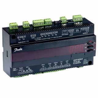
Dimensions

Principle

AKV info !!


Data communication
Important All connections to the data communication MODBUS and RS 485 must comply with the requirements for data communication cables. See literature: RC8AC.

System manager / Gateway


Connections

DI1
Digital input signal.
The defined function is active when the input is short-circuited/ opened. The function is defined in o02.
DI2
Digital input signal.
The defined function is active when the input is short-circuited/ opened. The function is defined in o37.
Pressure transmitter
AKS 32R
Connect to terminal 30, 31 and 32.
(Used cable 060G1034: Black=30, Blue=31, Brown=32)
The signal from one pressure transmitter can be received by up to 10 controllers. But only if there are no significant pressure decreases between the evaporators to be controlled.
S2, S6
Pt 1000 ohm sensor
S6 / S5B / S3B, product sensor or defrost sensor B or air sensor B.
The application determines which.
S3, S4, S5
Pt 1000 ohm sensor or PTC 1000 ohm sensor. All have to be of the same type.
S3, air sensor, placed in the warm air before the evaporator
S4, air sensor, placed in the cold air after the evaporator (the need for either S3 or S4 can be deselected in the configuration)
S5, defrost sensor, placed on the evaporator
EKA Display
If there is be external reading/operation of the controller, display type EKA 163B or EKA 164B can be connected.
RS485 (terminal 51, 52, 53)
For data communication, but only if a data communication module is inserted in the controller. The module can be a LON
RS485, DANBUSS or a MODBUS.
Terminal 51 = screen
Terminal 52 = A (A+)
Terminal 53 = B (B-)
(For LON RS485 and gateway type AKA 245 the gateway must be version 6.20 or higher.)
RJ45
For data communication, but only if a TCP/IP module is inserted in the controller. (OEM)
MODBUS
For data communication.
Terminal 56 = screen
Terminal 57 = A+
Terminal 58 = B-
(Alternatively the terminals can be connected to an external display type EKA 163A or 164A, but then they cannot be used for data communication. Any data communication must then be carried out by one of the other methods.)
Supply voltage
115 V a.c., 50/60 Hz
DO1
Connection of expansion valve type AKV or AKVA. The coil must be a 115 V a.c. coil.
DO2
Alarm
There is a connection between terminal 7 and 8 in alarm situations and when the controller is without power.
Rail heat and heating element in drip tray
There is connection between terminal 7 and 9 when heating takes place.
Night blind
There is connection between terminal 7 and 9 when the night blind is up.
Suction line valve
There is connection between terminal 7 and 9 when the suction line must be open.
DO3
Refrigeration, Rail heat, Heat function, Defrost 2
There is connection between terminal 10 and 11 when the function must be active.
Heating element in drip tray
There is connection between terminal 10 and 11 when heating takes place.
DO4
Defrost
There is connection between terminal 12 and 14 when defrosting takes place.
Hot gas / drain valve
There is connection between terminal 13 and 14 during normal operation.
There is connection between terminal 12 and 14 when the hot gas valves must open.
DO5
Fan
There is connection between terminal 15 and 16 when the fan is on.
DO6
Light relay
There is connection between terminal 17 and 18 when the light must be on.
Rail heat, Compressor 2
There is connection between terminal 17 and 19 when the function must be active.
DI3
Digital input signal.
The signal must have a voltage of 0 / 115 V a.c.
The function is defined in o84.
Data communication
If data communication is used, it is important that the installation of the data communication cable is performed correctly.
See separate literature No. RC8AC…
Electric noise
Cables for sensors, DI inputs and data communication must be kept separate from other electric cables:
– Use separate cable trays
– Keep a distance between cables of at least 10 cm
– Long cables at the DI input should be avoided
Installation considerations
Accidental damage, poor installation, or site conditions, can give rise to malfunctions of the control system, and ultimately lead to a plant breakdown.
Every possible safeguard is incorporated into our products to prevent this. However, a wrong installation, for example, could still present problems. Electronic controls are no substitute for normal, good engineering practice.
Danfoss will not be responsible for any goods, or plant components, damaged as a result of the above defects. It is the installer’s responsibility to check the installation thoroughly, and to fit the necessary safety devices.
Special reference is made to the necessity of signals to the controller when the compressor is stopped and to the need of liquid receivers before the compressors.
Your local Danfoss agent will be pleased to assist with further advice, etc.

Operation
Display
The values will be shown with three digits, and with a setting you can determine whether the temperature is to be shown in °C or in °F.

Light-emitting diodes (LED) on front panel
The LED’s on the front panel will light up when the relevant relay is activated.

The light-emitting diodes will flash when there is an alarm.
In this situation you can download the error code to the display and cancel/sign for the alarm by giving the top button a brief push.
The buttons
When you want to change a setting, the upper and the lower buttons will give you a higher or lower value depending on the button you are pushing. But before you change the value, you must have access to the menu. You obtain this by pushing the upper button for a couple of seconds – you will then enter the column with parameter codes. Find the parameter code you want to change and push the middle buttons until value for the parameter is shown. When you have changed the value, save the new valueby once more pushing the middle button.
Examples
Set menu
- Push the upper button until a parameter r01 is shown
- Push the upper or the lower button and find that parameter you want to change
- Push the middle button until the parameter value is shown
- Push the upper or the lower button and select the new value
- Push the middle button again to freeze the value.
Cutout alarm relay / receipt alarm/see alarm code
• A short press of the upper button
If there are several alarm codes they are found in a rolling stack.
Push the uppermost or lowermost button to scan the rolling stack.
Set temperature
1. Push the middle button until the temperature value is shown
2. Push the upper or the lower button and select the new value
3. Push the middle button again to conclude the setting.
Reading the temperature at defrost sensor (Or product sensor, if selected in o92.)
• A short press of the lower button Manuel start or stop of a defrost
• Push the lower button for four seconds. (However, not at Application 6)
Get a good start
With the following procedure you can start regulation very quickly:
- Open parameter r12 and stop the regulation (in a new and not previously set unit, r12 will already be set to 0 which means stopped regulation.)
- Select electrical connection based on the drawings on page 2 and 3
- Open parameter o61 and set the electric connection number in it
- Now select one of the preset settings from the table

5 Open parameter o62 and set the number for the array of presettings.
The few selected settings will now be transferred to the menu.
6 Select refrigerant via parameter o30
7 Open parameter r12 and start the regulation
8 Go through the survey of factory settings. The values in the grey cells are changed according to your choice of settings. Make any necessary changes in the respective parameters.
9 For network. Set the address in o03
10 Send address to system unit:
• MODBUS: Activate scan function in system unit
• If another data communication card is used in the controller:
– LON RS485: Activate the function o04


*) Can only be set when regulation is stopped (r12=0)
**) Can be controlled manually, but only when r12=-1
***) With access code 2 the access to these menus will be limited
Factory setting
If you need to return to the factory-set values, it can be done in this way:
– Cut out the supply voltage to the controller
– Keep upper and lower button depressed at the same time as you reconnect the supply voltage
Factory settings are indicated for standard units. Other code numbers have customized settings.


Data communication
The importance of individual alarms can be defined with a setting. The setting must be carried out in the group “Alarm destinations”

Read More About This Manual & Download PDF:
Documents / Resources
 |
Danfoss AK-CC 550A Controller For Appliance Control [pdf] Instructions AK-CC 550A Controller For Appliance Control, AK-CC 550A, Controller For Appliance Control, For Appliance Control, Appliance Control |
 |
Danfoss AK-CC 550A Controller for Appliance Control [pdf] User Guide AK-CC 550A Controller for Appliance Control, AK-CC 550A, Controller for Appliance Control, for Appliance Control, Appliance Control |


