![]() Instruction
Instruction
Manual
Ceiling Fan
FE-AA01/A CX10-5B/56
FE-AA03/B CX10-5B/46
FE-AA02/A CX10-5B/40
Safety Precaution
Warning
Installation and maintenance work shall only be performed by qualified persons, familiar with local code and regulation, and experienced with this type of appliance.
All field wiring must be installed in accordance with the national wiring regulation.
Ensure that the rated voltage of the unit corresponds to that of the name plate before commencing wiring work according to the wiring diagram.
The appliance must be permanently connected to the electricity supply through a double pole switch having a contact separation of at least 3mm in all poles.
The unit must be GROUNDED to prevent possible hazard due to insulation failure.
The earth wire is approximately 60mm longer than safety wire. This is to ensure at the event whereby the suspension system fails, the (L) and (N) wire will break leaving the fan remain earthed to prevent electrocution.
Tighten the blade firmly using a screw driver.
Blades that are detached from the unit during operation will cause serious injuries and property damages.
This appliance is not intended for use by persons (including children) with reduced physical, sensory or mental capabilities, or lack of experience and knowledge, unless they have been given supervision or instruction concerning use of the appliance by a person responsible for their safety.
Children should be supervised to ensure that they do not play with the appliances.
Confirm that the power supply has been switched OFF before installing or servicing the unit. Ensure that the blade is fully static before doing any maintenance work.
STOP using the ceiling fan when any abnormality or failure occurs.
If unusual oscillating movement is observed, immediately stop using the ceiling fan and contact the manufacturer, its service agent or suitably qualified persons.
CAUTION
Please take note of the following important points when installing.
The fixing means for attachment to the ceiling such as hooks or other devices shall be fixed with a sufficient strength to withstand 4 times the weight of the ceiling fan.
The mounting of the suspension system shall be performed by the manufacturer, its service agent or suitably qualified persons.
The fan is to be installed so that the blades are more than 2.5m above the floor.
Safety cord should not be longer than the earthing conductor.
Should failure of the suspension system occur, the supporting of the fan must not rely on the earthing conductor.The earthing terminal in the fan assembly should be such that should any part of the suspension system fall off, the body of the fan assembly shall effectively earthed.
Ensure that the unit’s panel is closed after service or installation.
Unsecured panels will cause the unit to operate noisily.
Sharp edges and coil surfaces are potential locations which may cause injury hazards. Avoid from being in contact with these places.
Before turning off the power supply set the remote controller’s ON/OFF switch to the “OFF” position.
If this is not done, the unit’s fans will start turning automatically when power resumes, posing a hazard to service personnel or the user.
Do not operate any heating apparatus too close to the ceiling fan unit or use in room where mineral oil, oil vapour or oil steam exist, this may cause plastic part to melt or deform as a result of excessive heat or chemical reaction.
Avoid the ceiling fan unit from exposing to direct sunlight, this may cause degradation of plastic material as a result of excessive heat and UV radiation.
Ensure the colour of wires of the outdoor unit and the terminal markings are same to the indoors respectively.
Do not use joined and twisted wires for incoming power supply.
Do not place any object in the path of the blades. Avoid raising objects or your arms near the ceiling fan. The fan suspension system and blade screw tightening shall be examined yearly.
Replacement of parts of the safety suspension system device shall be performed by the manufacturer, its service agent or suitably qualified persons.
Torque value for screw/bolts for securing primary suspension system for motor is 2Nm.
Parts & Accessories

Installation Instruction
IMPORTANT: SWITCH OFF THE ELECTRICAL MAINS AT THE CIRCUIT BREAKER FUSE BOX.
Step 1
a. Insert the Motor Bracket Motor to the Motor Shaft.
b. Route Motor wires and Safety cable through the Downrod.
c. Fix the Motor Bracket and Downrod to the Motor Assembly with Bolt, Washer, Nut and tighten them firmly then insert the Clevis Pin.
IMPORTANT : Clevis Pin MUST be inserted to prevent Nut from loosening.
Step 2
a. Assemble the Canopy and Coupling Cover through the Downrod.
b. Fix the Rubber Pulley Assembly to the Downrod with Bolt, Washer, Nut and tighten them firmly, then insert the Clevis Pin.
Step 3
a. Remove the Bolt, Clevis Pin, Nut, Washer and Rubber Pulley from the Downrod.
b. Place the Rubber Pulley onto the ceiling hook.
c. Fix back the Bolt, Clevis Pin, Nut and Washer.
IMPORTANT : Clevis Pin MUST be inserted to prevent Nut from loosening. Step 4
a. Remove the Safety Wire screw and washer from the Downrod.
b. Install the Safety Cable. Step 5
Connect the Connectors from Fan and Receiver.
Connect the wires from the receiver to House’s Supply Wire.
Connect Earth Wire to House Supply Earth Terminal. Step 6
Install the Blades on Motor with Blade Screw and Washer.
IMPORTANT: Assemble the Fan Blades only after the ceiling fan is mounted on the hook. Below shows a complete installation diagram.
Transmitter Learning Process
IMPORTANT : DO NOT CONNECT THIS REMOTE CONTROL CEILING FAN TOL REGULATOR OR DIMMER SWITCH.
The receiver & transmitter is pre-programmed in factory. If you wish to control 2 or more fans using 1 transmitter, the below steps are required.
DO NOT PRESS ANY OTHER BUTTON DURING THIS PROCESS
Step 1
a) Insert the 2 pcs of batteries (provided) into transmitter.
b) TTurn on the power supply (wall switch) to the fan.
c) Within 30 sec., press and hold the “OFF” button for 3 sec. Once the receiver has detected the frequency, transmitter will “Beep Beep” twice. Programming process is completed and fan is ready to use.
If the fan is not responding to the transmitter, repeat Step 1b.
Transmitter Assembly & Operation
IMPORTANT : DO NOT CONNECT THIS REMOTE CONTROL CEILING FAN TO REGULATOR OR DIMMER SWITCH.
Function of Transmitter
![]() – Turn off fan.
– Turn off fan.
– Fan speed lowest to highest.
– Natural wind, creating gentle sea-breeze effect.
![]() – Forward/Reverse, turn anti-clockwise or clockwise rotation.
– Forward/Reverse, turn anti-clockwise or clockwise rotation.
![]() – Fan speed will decrease gradually every 30 minutes until reach to speed 1
– Fan speed will decrease gradually every 30 minutes until reach to speed 1
![]() – Natural wind, creating gentle sea-breeze effect.
– Natural wind, creating gentle sea-breeze effect.
1H – Timer off – fan turns off after 1hr.
3H – Timer off – fan turns off after 3hr.
6H – Timer off – fan turns off after 6hr.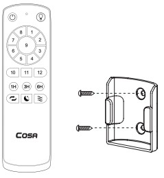 Mount the remote control holder on the wall with the screws provided.
The transmitter & receiver is incorporated with last memory function. This function stores your last setting in memory and the next time you turn on the fan, fan will operate as the last setting.
Function of Forward & Reverse
Fan must be turned on and rotating.
Press Forward/Reverse button and fan will slow down and then change direction (approx. 15 sec). When the fan is slowing down to change direction, the Fan Speed function is disabled until direction has been changed.  Forward
Fan rotates anti-clockwise blowing the air downwards creating the wind chill effect. Suitable for hot weather condition. Reverse
Fan rotates clockwise drawing the air towards the ceiling circulating the warm air downwards. This function works best at low speed. Suitable for air-conditioned condition.
Power Supply Connection
 IMPORTANT : DO NOT CONNECT THIS REMOTE CONTROL CEILING FAN TO REGULATOR OR DIMMER SWITCH.
Circuit Diagram

Maintenance
Due to the fan’s natural movement, connections may get loose after period of usage. To ensure a proper and safety usage, it is highly recommended to inspect and tighten all connections every 6 months.
Cleaning
Cleaning your fan periodically will prolong its new appearance. Basic cleaning procedures are as follows :
- Use only water and mild soap. Do not use solvents, corrosive or acidic solution.
- Damp the cloth lightly. Use only soft or lint-free cloth to clean the fan. Rough fabric will scratch the surface.
- Do not bent the blades while cleaning. At the event where blades are bent or damage, order new set of blades from service center or dealer shop.
- There is no need to oil the fan.
Technical Specifications
| Model | FE-AA01/A | FE-AA03/B | FE-AA02/A |
| Alt. Name | CX10-5B/56 | CX10-5B/46 | CX10-5B/40 |
| No. Of Blades | 5 | ||
| Fan Width | 1420mm (56″) | 1168mm (46″) | 1015mm (40″) |
| Motor RPM | 75 – 203 | 75 – 233 | 84 – 226 |
| Voltage | 220-240W 50Hz | ||
| Motor Wattage | 4W – 45W 4W – 40W | 4W – 40W | |
| Nett Weight | 4.7kg 1 4.3kg |
4.3kg | |
| Gross Weight | 5.7kg 1 5.3kg | 5.3kg | |
Technical Specifications
 Customer Service Centre
If you need any technical assistance or faulty report, please contact our customer service centre at :
Alpha Home Appliances Sdn. Bhd. (390258-H)
Head Office : 6, Jalan Sungai Kayu Ara 32/37, Berjaya Park, Section 32, 40460 Shah Alam, Selangor.
![]() Tel : 03-5740 6666
Tel : 03-5740 6666
Website : www.alphamalaysia.com
Fax : 03-5740 8220
Email : info@alphamalaysia.com
Johor Bahru : 71, Jalan Molek 3/10, Taman Molek, 81100 Johor Bahru.
Tel : 07-353 4833 / 4933 Fax : 07-355 4233
Melaka : 19, 19-1 & 19-2, Jalan KSB 11,
Tel : 06-292 6292 / 6293
Taman Kota Syahbandar, 75200 Melaka.
Fax : 06-292 6296
Ipoh : 11, Laluan Tasek Timur 5, Taman
Tel : 05-545 2282 / 547 2282
Tasek Indra, 31400 Ipoh, Perak.
Fax : 05-547 6282
Penang : 28, Jalan Icon City, Icon City
Tel : 04-506 2366 / 2066 / 2566
14000 Bukit Mentajam, Penang.
Fax : 04-506 2966
Pahang : A131, TK1, Jalan Wang Ah Jang,
Tel : 09-516 5226
Taman Liza, 25100 Kuantan, Pahang.
Fax : 09-513 9226
Documents / Resources
 |
COSA FE-AA0 Series Ceiling Fan [pdf] Instruction Manual FE-AA01-A CX10-5B-56, FE-AA03-B CX10-5B-46, FE-AA02-A CX10-5B-40, FE-AA0 Series Ceiling Fan, FE-AA0 Series, Ceiling Fan, Fan |