![]() HEDS-9940PRGEVB
HEDS-9940PRGEVB
Evaluation Board and Programming Kit
User Guide
Version 1.0
HEDS-9940PRGEVB Evaluation Board and Programming Kit
Copyright © 2024 Broadcom. All Rights Reserved. The term “Broadcom” refers to Broadcom Inc. and/or its subsidiaries. For more information, go to www.broadcom.com. All trademarks, trade names, service marks, and logos referenced herein belong to their respective companies.
Broadcom reserves the right to make changes without further notice to any products or data herein to improve reliability, function, or design. Information furnished by Broadcom is believed to be accurate and reliable. However, Broadcom does not assume any liability arising out of the application or use of this information, nor the application or use of any product or circuit described herein, neither does it convey any license under its patent rights nor the rights of others.
HEDS-9940EVB Evaluation Board
1.1 Top and Bottom Views
Figure 1: Bottom View of the PCB

Figure 2: Top View of the PCB

The silk screen-printed guide line on the PCB is to help in providing visual alignment of the code wheel edge (outer diameter) for each of the different ROP (CPR) tracks. A sample diagram showing the position when the encoder is aligned to the 500 CPR track is shown in Figure 3.
Figure 3: Sample Encoder Aligned to 500 CPR Track (HEDS-9940EVB1/HEDS-9940PRGEVB1)

Figure 4: Sample Evaluation Board Mounting with Reference to Code Wheel

Select Options
Table 1: Selection Table for AEDR-9940 198.4375 LPI
| No. | SEL1 | SEL2 | SEL3 | Interpolation Factor | INDEXSEL | Index |
| 1 | Low | Low | Low | 1X | Low | Interpolation 1X – Index Gated 90 degrees |
| High | Interpolation lx – Index Gated 180 degrees | |||||
| Open | Interpolation 1X – Index Raw (Ungated) | |||||
| 2 | High | Low | Low | 2X | Low | Interpolation 2X – Index Gated 90 degrees |
| High | Interpolation 2X – Index Gated 180 degrees | |||||
| Open | Interpolation 2X – Index Gated 360 degrees | |||||
| 3 | Opena | Low | Low | 3X | Low | Interpolation 3X – Index Gated 90 degrees |
| High | Interpolation 3X – Index Gated 180 degrees | |||||
| Open | Interpolation 3X – Index Gated 360 degrees | |||||
| 4 | Low | High | Low | 4X | Low | Interpolation 4X – Index Gated 90 degrees |
| High | Interpolation 4X – Index Gated 180 degrees | |||||
| Open | Interpolation 4X – Index Gated 360 degrees | |||||
| 5 | High | High | Low | 5X | Low | Interpolation 5X – Index Gated 90 degrees |
| High | Interpolation 5X – Index Gated 180 degrees | |||||
| Open | Interpolation 5X – Index Gated 360 degrees | |||||
| 6 | Open° | High | Low | 6X | Low | Interpolation 6X – Index Gated 90 degrees |
| High | Interpolation 6X – Index Gated 180 degrees | |||||
| Open | Interpolation 6X – Index Gated 360 degrees | |||||
| 7 | Low | Open° | Low | 8X | Low | Interpolation 8X – Index Gated 90 degrees |
| High | Interpolation 8X – Index Gated 180 degrees | |||||
| Open | Interpolation 8X – Index Gated 360 degrees | |||||
| 8 | High | Open° | Low | 9X | Low | Interpolation 9X – Index Gated 90 degrees |
| High | Interpolation 9X – Index Gated 180 degrees | |||||
| Open | Interpolation 9X – Index Gated 360 degrees | |||||
| 9 | Opena | Open° | Low | 10X | Low | Interpolation 10X – Index Gated 90 degrees |
| High | Interpolation 10X – Index Gated 180 degrees | |||||
| Open | Interpolation 10X – Index Gated 360 degrees | |||||
| 10 | Low | Low | High | 12X | Low | Interpolation 12X – Index Gated 90 degrees |
| High | Interpolation 12X – Index Gated 180 degrees | |||||
| Open | Interpolation 12X – Index Gated 360 degrees | |||||
| 11 | High | Low | High | 16X | Low | Interpolation 16X – Index Gated 90 degrees |
| High | Interpolation 16X – Index Gated 180 degrees | |||||
| Open | Interpolation 16X – Index Gated 360 degrees | |||||
| 12 | Opena | Low | High | 20X | Low | Interpolation 20X – Index Gated 90 degrees |
| High | Interpolation 20X – Index Gated 180 degrees | |||||
| Open | Interpolation 20X – Index Gated 360 degrees | |||||
| 13 | Low | High | High | 25X | Low | Interpolation 25X – Index Gated 90 degrees |
| High | Interpolation 25X – Index Gated 180 degrees | |||||
| Open | Interpolation 25X – Index Gated 360 degrees | |||||
| 14 | High | High | High | 32X | Low | Interpolation 32X – Index Gated 90 degrees |
| High | Interpolation 32X – Index Gated 180 degrees | |||||
| Open | Interpolation 32X – Index Gated 360 degrees | |||||
| High | High | 50X | Low | Interpolation 50X – Index Gated 90 degrees | ||
| High | Interpolation 50X – Index Gated 180 degrees | |||||
| Open | Interpolation 50X – Index Gated 360 degrees | |||||
| 16 | Opena | High | 64X | Low | Interpolation MX – Index Gated 90 degrees | |
| High | Interpolation MX – Index Gated 180 degrees | |||||
| Open | Interpolation MX – Index Gated 360 degrees | |||||
| 17 | High | Opena | High | 80X | Low | Interpolation 80X – Index Gated 90 degrees |
| High | Interpolation 80X – Index Gated 180 degrees | |||||
| Open | Interpolation 80X – Index Gated 360 degrees | |||||
| 18 | Open° | Open° | High | 100X | Low | Interpolation 100X – Index Gated 90 degrees |
| High | Interpolation 100X – Index Gated 180 degrees | |||||
| Open | Interpolation 100X – Index Gated 360 degrees | |||||
| 19 | Opena | 128X | Low | Interpolation 128X – Index Gated 90 degrees | ||
| High | Interpolation 128X – Index Gated 180 degrees | |||||
| Open | Interpolation 128X – Index Gated 360 degrees | |||||
| 20 | High | Opena | 160X | Low | Interpolation 160X – Index Gated 90 degrees | |
| High | Interpolation 160X – Index Gated 180 degrees | |||||
| Open | Interpolation 160X – Index Gated 360 degrees | |||||
| 21 | Opena | Low | Opena | 256X | Low | Interpolation 256X – Index Gated 90 degrees |
| High | Interpolation 256X – Index Gated 180 degrees | |||||
| Open | Interpolation 256X – Index Gated 360 degrees | |||||
| High | Opena | 320X | Low | Interpolation 320X – Index Gated 90 degrees | ||
| High | Interpolation 320X – Index Gated 180 degrees | |||||
| Open | Interpolation 320X – Index Gated 360 degrees | |||||
| 23 | High | High | Opena | 640X | Low | Interpolation 640X – Index Gated 90 degrees |
| High | Interpolation 640X – Index Gated 180 degrees | |||||
| Open | Interpolation 640X – Index Gated 360 degrees | |||||
| 24 | Open” | High | Opena | 1000X | Low | Interpolation 1000X – Index Gated 90 degrees |
| High | Interpolation 1000X – Index Gated 180 degrees | |||||
| Open | Interpolation 1000X – Index Gated 360 degrees | |||||
| 25 | Low | Open° | Opena | Ungated Digital | Low | Analog SIN/COS (500 mVpp). Digital Index (Ungated) |
| High | Analog SIN/COS (500 mVpp). Digital Index (Ungated) | |||||
| Open | Analog SIN/COS (500 mVpp). Digital Index (Ungated) | |||||
| 26 | High | Opena | Opena | Analog | Low | Analog SIN/COS (500 mVpp), Analog Index (1 Vpp) |
| Ungated Digital | High | Analog SIN/COS (1 Vpp), Digital Index (Ungated) | ||||
| Analog | Open | Analog SIN/COS (1 Vpp), Analog Index (1Vpp) | ||||
| 27 | Opena | Opena | Opena | SPI Mode | Low | SPI Mode: Program Selection |
| High | SPI Mode: Output Enabled | |||||
| Open | SSI 3W Modeb |
a. Open selection must be connected to the middle of a voltage divider circuit. See Figure 5.
b. SSI 3W mode is for monitoring purposes only.
Figure 5: Voltage Divider Circuit

Use 2 x 4.7-kΩ resistors (VCC to GND).
The digital interpolation factor is based on the following equation for various rotational speeds (RPM) and count per revolution (CPR) values.
RPM = (Count Frequency x 60) / CPR
CPR (@ 1X interpolation) is based on the following equation that is dependent on radius of operation (ROP).
CPR = LPI x 2π x ROP (inch) or CPR = LP mm x 2π x ROP (mm)
NOTE: LP mm (lines per mm) = LPI / 25.4
2.1 Programmable Select Options
SPI programmable with interpolation factor from 1X to 1024X.
- Configure external selection to SPI Mode: Program Selection.
- For signals output after configuration, set external selection to SPI Mode: Output Enabled.
Board Schematic and Pin Assignment
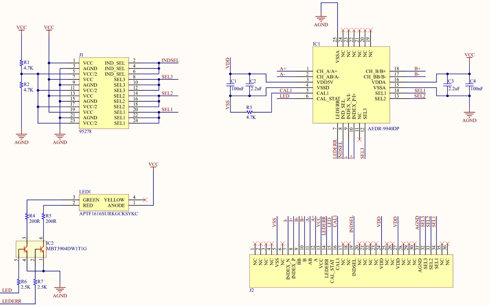
Figure 6: HEDS-9930EVB Evaluation Board Schematic
3.1 Connector Assignment
Table 2: Connector 1 Pin Assignment
| Connector 1 (Top Side) | Label | Connector 1 (Bottom Side) | Label |
| 1 | NC | 1 | NC |
| 2 | NC | 2 | NC |
| 3 | SEL1 | 3 | CALI |
| 4 | SEL2 | 4 | CAL STAT |
| 5 | SEL3 | 5 | LEDERR |
| 6 | AGND | 6 | VCC |
| 7 | NC | 7 | A+ |
| 8 | NC | 8 | A- |
| 9 | NC | 9 | B+ |
| 10 | VDD | 10 | B- |
Table 2: Connector 1 Pin Assignment
| Connector 1 (Top Side) | Label | Connector 1 (Bottom Side) | Label |
| 11 | NC | 11 | I+ |
| 12 | NC | 12 | I- |
| 13 | VDD | 13 | NC |
| 14 | NC | 14 | VSS |
| 15 | NC | 15 | NC |
| 16 | NC | 16 | NC |
| 17 | NC | 17 | NC |
| 18 | INDSEL | 18 | NC |
The finger design of Connector 1 is a match to either of the following card edge connectors:
- EDAC, CONN EDGE DUAL FMALE 36POS 0.100, P/N# 395-036-520-202
- SULLINS, CONN EDGE DUAL FMALE 36POS 0.100, P/N# EBC18DREH
The use of the above mentioned card edge connector is not needed if necessary connections can be made using manual soldering to the relevant card edge fingers.
Table 3: Connector 2 Pin Assignment
| Connector 1 (Top Side) | Label | State |
| 1 | SEL1 | VCC |
| 2 | AGND | |
| 3 | OPEN | |
| 4 | SEL2 | VCC |
| 5 | AGND | |
| 6 | OPEN | |
| 7 | SEL3 | VCC |
| 8 | AGND | |
| 9 | OPEN | |
| 10 | INDEX SEL | VCC |
| 11 | AGND | |
| 12 | OPEN |
NOTE: Refer to Table 1, Selection Table for AEDR-9940 198.4375 LPI for the various interpolation selection options available by changing the SEL1, SEL2, and SEL3 jumper positions.
Code Wheel Drawing
For the AEDR-9940 evaluation board sample, the matching code wheel sample drawings are shown in the following figures.
For a detailed drawing of the sample code wheel, request from your regional FAE.
Figure 7: Code Wheel Multiple Optical Radius 200, 360, 500, 625 CPR Base
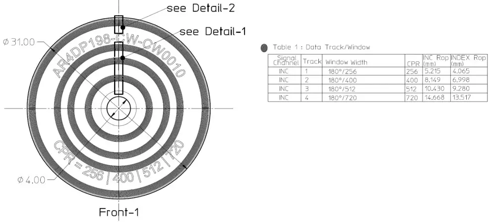
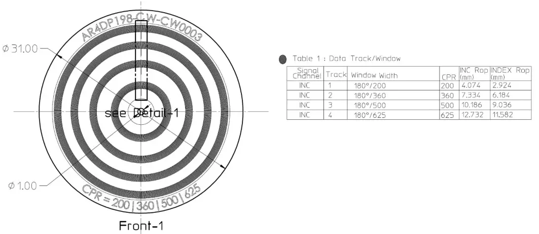 Figure 8: Code Wheel Multiple Optical Radius 256, 400, 512, 720 CPR Base
HEDS-9940PRGEVB Programming USB-SPI Kit
In order to program interpolation value other than the ones offered in Table 1, Selection Table for AEDR-9940 198.4375 LPI using the SEL1, SEL2, and SEL3 option pins, you may connect to the AEDS-9940 encoder ASIC through the SPI interface.
Broadcom® offers a simple USB to SPI programming kit, together with a PC-based custom program for you to program the desired interpolation value.
Figure 9: The HEDS-9940PRGEVB USB to SPI Programmer Kit
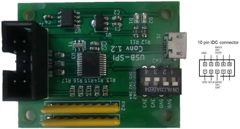
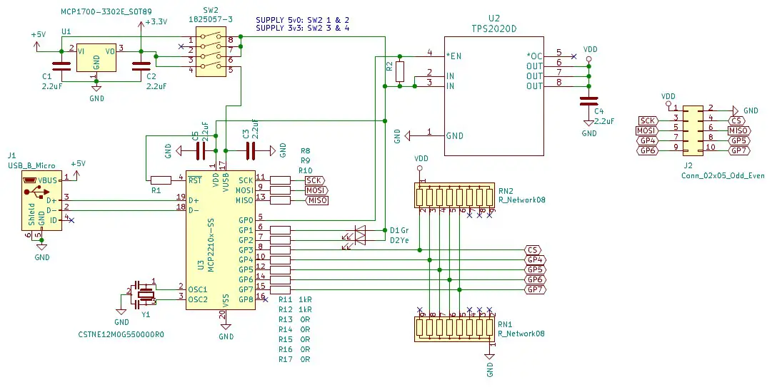
Figure 10: The HEDS-9940PRGEVB USB to SPI Programmer Kit Schematic
AEDR-9940 Gateway Programming GUI
The HEDS-9940PRGEVB kit is to be used together with AEDR_9940_Gateway.exe to program the desired interpolation factor into the encoder ASIC.
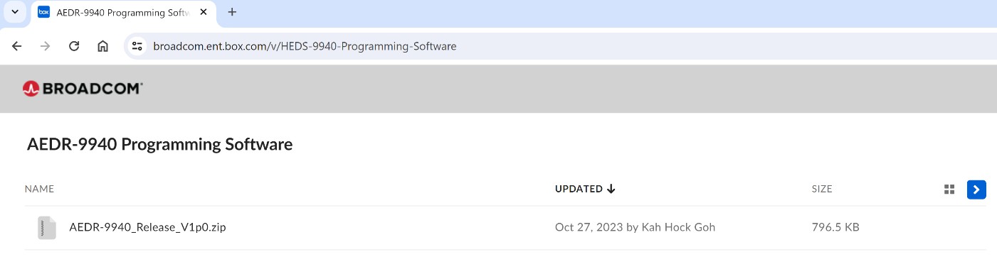
- Download the zip file from: https://broadcom.box.com/v/HEDS-9940-Programming-Software
- Save the zip file into a local drive on your PC.
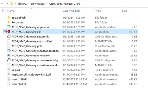
- Unzip AEDR-9940_Release_Vxpx.zip to a local folder of your choice.

- Double-click AEDR_9940_Gateway.exe.
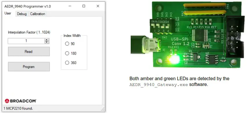
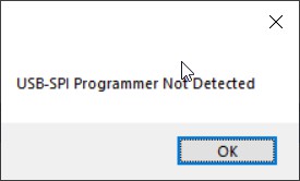
- Once the AEDR_9940_Gateway.exe software is running, the board should be detected.
- If the following message appears, check the board connections and try again.
- Click Read to read back saved settings from the AEDR-9940 encoder ASIC.
a. If existing settings are read out successfully, it displays the saved Interpolation Factor and Index Width settings.
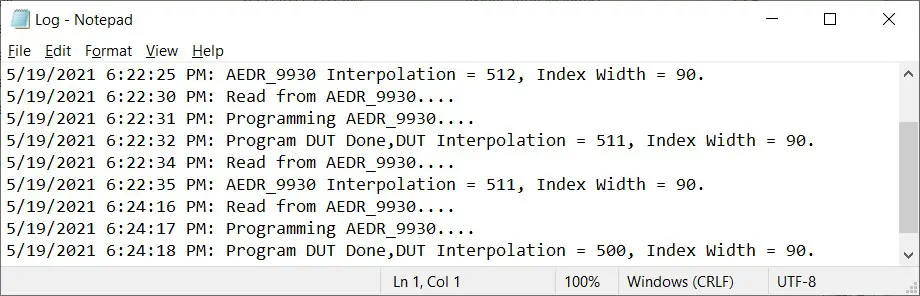 b. If the AEDR-9940 is not connected or detected, the program terminates. Refer to log.txt in the same directory to check the failure status.
c. If there is a communication failure with the AEDR-9940, the program exits. Refer to log.txt to check the error message. - Enter the interpolation factor required (1 to 1024) and index width setting. Click Program to save the settings.
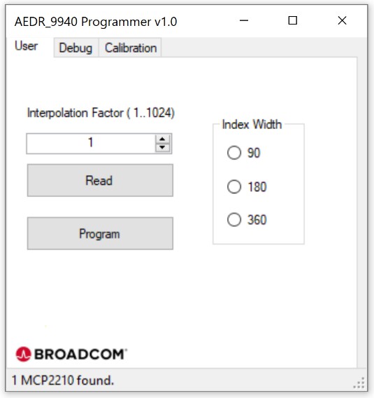
- The message Program DUT OK! displays when the settings are save successfully.
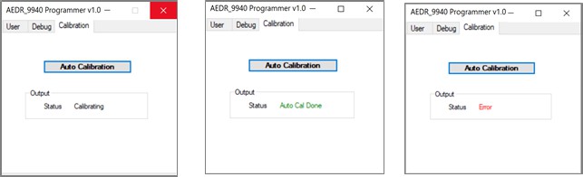
Using the AEDR-9940 Gateway SPI Protocol to Perform Calibration
Motor rotation with minimal speed ripple or smooth linear movement is required during calibration. This is to enable Index signals to be automatically adjusted to obtain a good crossover.
- Turn the motor at a constant speed of 500 rpm or linear stage reciprocal movement (stroke[50 mm/s])
- Click Auto Calibration.
- Calibration in progress. Calibrating displays in Status.
- The Status displays Auto Cal Done if calibration is successfully completed. Otherwise, it displays Error.
NOTE: A calibration error may be caused by wide spatial displacement or failure to obtain index signals crossover.
![]() HEDS-9940PRGEVB User Guide
HEDS-9940PRGEVB User Guide
Evaluation Board and Programming Kit
Documents / Resources
 |
BROADCOM HEDS-9940PRGEVB Evaluation Board and Programming Kit [pdf] User Guide HEDS-9940PRGEVB, HEDS-9940PRGEVB Evaluation Board and Programming Kit, Evaluation Board and Programming Kit, Board and Programming Kit, Programming Kit, Kit |


